Lintel PSB-10 User manual

Rolling thin-film oven (RTFOT)
LinteL® PSB-10
Operating manual

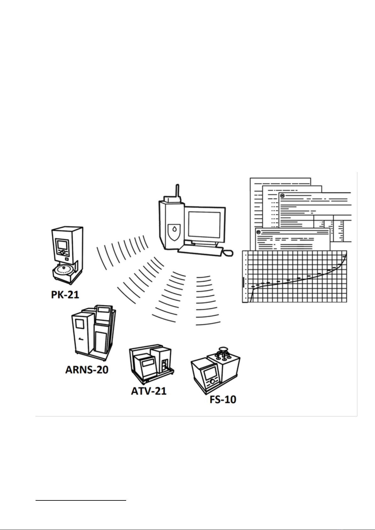
WIRELESS INTERFACE SUBSYSTEM
Wireless interface subsystem (further WIS) is designed for operation automation of petroleum product
quality control laboratories.
Wireless interface subsystem has the following functions:
automatic transfer of test results from the tester located in the laboratory to PC via wireless
communications channel (IEEE 802.15.4/ZigBee standard);
safe storage of information obtained from the tester in a common database;
user-friendly, standardized representation of information to the user (in a table-oriented, graphical,
printed view);
providing tools for effective work with test results, tools for calculating accuracy characteristics using
standard methods.
Wireless interface subsystem provides communication at the distance up to 100 m indoors, all LinteL®
tester can be integrated in a common network.
LinteL®tester are equipped with hardware and software providing tester operation with the Wireless
Interface Subsystem
1
.
System operation requires purchase and installation of a radio modem with USB interface and
PC software. The software includes data communication protocol driver and LinteL®- LINK software.
Test results are automatically transferred to the database, which simplifies access to data and sched-
ules, improves the quality of work, and eliminates most routine operations.
1
For additional information, please, call + 7 (347) 284-44-36, 284-27-47.

Up-to-date devices for petroleum product quality control
Thank you for purchasing and usage of LinteL®PSB-10 –laboratory tester for the effect of high tempera-
ture and air on a moving thin film of bitumen.
Since 1959, BSDO Neftehimavtomatika JSC has been manufacturing and supplying tester for quality con-
trol of petroleum products in the laboratories of factories, airports, and fuel and energy complex enter-
prises.
Our tester implement STANDARD METHODS, have passed metrological certification, are included in MI
2418-97 "Classification and application of technical means of testing of petroleum products" and the
corresponding GOSTs Standards as a means of implementing quality control methods.
The tester has special solutions that allow you to implement in addition to standard methods and
methods for performing research, which is especially important when developing new types of
products. LinteL uses the latest technologies and components to ensure consistently high quality of
tester, convenience of their operation, in order to reduce the time spent on testing and increase the
efficiency of your work.
The LinteL® PSB-10 tester you purchased uses the best achievements in the development of products of
this type:
modern control device with the primary use of imported components and components of high relia-
bility;
four-line character LCD display;
the self-diagnosis system of the tester increases the reliability of the tester;
set of measures to protect against operator errors;
power supply module that allows the tester to remain operational in an extended range of network
voltages: from 198 to 242 V AC with a frequency of 50 Hz.

CONTENT
1LIST OF ABBREVIATIONS .................................................................................................................2
2DESCRIPTION AND OPERATION.......................................................................................................2
2.1 Purpose .................................................................................................................................................. 2
2.2 Specifications ......................................................................................................................................... 2
2.3 Arrangement and operation.................................................................................................................. 3
3PREPARATION FOR OPERATION ......................................................................................................5
3.1 Requirements for installation place....................................................................................................... 5
3.2 Visual control ......................................................................................................................................... 6
3.3 Test run .................................................................................................................................................. 6
4INTENDED USE................................................................................................................................6
4.1 Operating limits ..................................................................................................................................... 6
4.2 Sample preparation ............................................................................................................................... 7
4.3 Oven preparation for testing ................................................................................................................. 7
4.4 Testing.................................................................................................................................................... 8
4.5 Work completion ................................................................................................................................... 9
4.6 List of potential failures ......................................................................................................................... 9
4.7 Contingency actions............................................................................................................................. 10
4.8 Additional function .............................................................................................................................. 10
5MAINTENANCE .............................................................................................................................13
5.1 Additional equipment and materials................................................................................................... 13
5.2 List of operations ................................................................................................................................. 13
5.3 Wiping the display surface................................................................................................................... 13
5.4 Calibration of the oven temperature sensor....................................................................................... 13
5.5 Calibration of the air flow sensor ........................................................................................................ 15
5.6 Viewing drum calibration coefficients................................................................................................. 15
6STORAGE AND TRANSPORTATION.................................................................................................15
6.1 Storage................................................................................................................................................. 15
6.2 Transportation ..................................................................................................................................... 16

2AIF 2.772.022 RE
The operating manual contains information about the design, operating principle, characteristics of the
automatic LinteL® PSB-10 and instructions necessary for its correct and safe operation.
1LIST OF ABBREVIATIONS
Tester –oven LinteL® PSB-10.
PC –personal computer.
PSD –protective shutdown device.
2DESCRIPTION AND OPERATION
2.1 Purpose
Tester for determining the aging of bitumen under the influence of high temperature and air LinteL®
PSB-10 (further - the oven) manufactured according to NTVR.441336.058 TU. Is a test equipment of a
desktop type and is intended for carrying out the effect of high temperature and air on the moving thin
film of bitumen in accordance with standards GOST 33140, EN 12607-1.
2.2 Specifications
2.2.1 Performance data of the oven given in Table 1.
Table 1 –Performance data
Parameters
Unit of meas-
urement
Value
GOST 33140
EN 12607-1
Oven temperature after stabilization
°С
from 162 to 164
from 162 to 164
Air flow through the flow sensor
liter/min
from 3,8 to 4,2
from 3,8 to 4,2
Drum speed after acceleration
rpm
from 14,8 to 15,2
from 14,8 to 15,2
Fan speed after acceleration
rpm
from 1625 to
1825
from 1650 to
1850
Test duration
min
from 84 to 86
from 74 to 761
Time of heating of the oven after placing
samples in the oven 2, no more
min
15
15
Voltage
V
from 198 to 242
Frequency
Hz
from 49 to 51
Power consumption, no more than
Kilowatt (kW)
2,1
Ambient temperature
0С
from 17 to 25
Relative humidity, not more than
%
80
Barometric pressure
mm Hg
from 680 to 800
2.2.2 Weight and dimensions of the oven given in table 2.
Table 2 –The overall dimension
Parameter
Unit of
measure-
ment
Value
Weight of the oven
kg
120
Dimensions of the oven (width x height x depth)
mm
916,6х826х823
2.2.3 The accuracy parameters of the oven given in table 3.
1
After reaching the test temperature
2
At 220 V network voltage and correct initial temperature selection.

LinteL® PSB-10 3
Table 3 –The accuracy characteristics
Parameter
Unit of
measurement
Value
Accuracy of the fan rotation speed
min-1
±100
Accuracy of the drum rotation speed
min-1
±0,2
The accuracy of the feed rate of hot air
liter/min
±0,2
Accuracy of maintaining the temperature of the inter-
nal space
°С
±1
The manufacturer guarantees that the accuracy parameters confirmed during the initial certification af-
ter transportation remain unchanged.
2.2.4 Oven possibility
1) testing and notification of the end time;
2) automatic blocking and signaling in case of incorrect operator actions or malfunctions of individual
nodes;
3) protection against starting the test when the door is open.
2.3 Arrangement and operation
2.3.1 Scope of delivery:
1) Tester LinteL®PSB-10 AIF 2.772.022.
2) Operational documents:
Operating manual AIF 2.772.022 RE;
Passport AIF 2.772.022 PS;
Certification program and procedure AIF 2.772.022 MA.
3) Attachment.
2.3.2 General information
The main function of the oven include:
1) ensuring stable test conditions (automatic maintenance of oven temperature, air flow, drum rotation
speed and fan rotation speed);
2) warning the operator about the end of the test time with sound signal.
2.3.3 Oven desing
2.3.3.1 The general view of the oven is shown in Figure 1, page 4. The main elements of the oven are
door 1, door handle 2, drum 3, fan 4, coil 5, temperature sensor 6, front panel 7. On the bottom right is
the «Network»switch 8, intended to activate the oven’s power supply. Using the adjusting legs 9, the
horizontal position of the oven is adjusted. The hole 10 is used to place an exemplary thermometer
inside the oven.
2.3.3.2On the rear wall of the oven (figure 2, page 4) are the input of the power cord 1, the protective
disconnection device 2, the grounding pin 3.
2.3.3.3 The front panel (figure 3, page 4) contains the display 1 and the oven controls: the control knob
2, and the buttons 3. The purpose of the controls is shown in table 4, page 5.

4AIF 2.772.022 RE
Figure 1 –General view of the oven (front view)
1
2
3
Figure 2 –Rear wall of the oven
Figure 3 –The front panel

LinteL® PSB-10 5
Table 1 –Designation of oven controls
Button
Modes of operation of the oven
Action
«Mode»
screen saver
entering the service menu
waiting
entering the main menu
editing numeric parameters
cycling cursor to the left –accordingly, edited
number digits
«*»
test completed
display of maximum and minimum parame-
ter values during the test
editing numeric parameters
cycling cursor to the right –accordingly, edit-
ed number digits
«Stop»
menu, service
transition to standby mode
printing parameters, printing errors, re-
setting settings
transition to the service menu
interface, operating time, sensors, cali-
bration, «exit» item in the «equipment
test»menu
transition to the main menu
t°calibration, flow calibration, drum cal-
ibration
return to the «calibration» menu
oven heating, stable
return to standby mode
test
transition to «test completed»
test completed
transition to «heating the oven»
display of maximum and minimum pa-
rameters during the test, display of heat-
ing time
transition to «test completed»
editing numeric parameters
exit editing mode without saving changes
equipment test
finish testing the selected equipment
«Start»
waiting
starting the heating of the oven
stably/unstably
running a test
display of maximum and minimum pa-
rameters during the test, display of heat-
ing time
transition to «test completed»
displaying any type of menu
selecting the current menu item
editing numeric parameters
exit edit mode and save changes
equipment test
start testing the selected equipment
Control
knob
(rotation)
being in any menu
navigate through the list items (move the
pointer to the current item ►)
editing numeric parameters
changing the number starting from the digit
that the cursor points to _
3PREPARATION FOR OPERATION
3.1 Requirements for installation place
3.1.1 The oven is a desktop -type laboratory tester.
3.1.2 The place of installation of the oven should exclude the impact of shaking, shocks, vibrations that
affect the normal operation of the oven.

6AIF 2.772.022 RE
3.1.3 The oven should be installed horizontally using a level.
3.1.4 The European standard socket used for powering the oven should have a ground connection to
«ground» bus that is not connected to the power equipment.
3.1.5 Connect the ground terminal (see figure 2, page 4) to an external ground bus that is not connected
to the power equipment.
3.1.6 Switch the protective disconnection device (see figure 2, page 4) to the on state (toggle switch up).
3.1.7 Check the cup retainers inside the drum. In order to avoid falling out of glass test cup during oper-
ation, it is necessary that they securely fix the glass test cup.
ATTENTION
If the oven is not installed horizontally, the glass test cup may fall out of the drum during the test.
3.2 Visual control
Before using the oven:
1) unpack the oven;
2) check scope of supply;
3) perform visual control of the oven for damage;
4) check for supporting documentation.
An appropriate report is drawn up for all defects.
3.3 Test run
ATTENTION
After entering the heated room from a zone with a temperature below 10°C, keep the oven in the
package for at least 4 hours.
3.3.1 Turn on the oven with the «Network» toggle switch 8 (see figure 1, page 4). The display shows the
download window (see figure 4), where X. XX is the software configuration.
Figure 4 –Download window
3.3.2 After 10 seconds or by pressing the [Start] button on the front panel, the oven will switch to
standby mode (see figure 5).
Figure 5 –Waiting window
Parameter
Value
Temp. oven,°C
oven temperature according to the built -in temperature sensor
Drum, rpm
the speed of the drum
Compressor
off –compressor is turned off
4INTENDED USE
4.1 Operating limits
1) when connecting to a network of ~ 220 V 50 Hz, it is necessary use a socket that meets the Europe-
an standard (with a ground terminal);
2) it is forbidden to perform maintenance of the oven included in the network;
WAITING GOST 33140
t oven,°C 25.3
Drum,rpm 0.0
Compressor off

LinteL® PSB-10 7
3) the oven can be switched on again no earlier than 5 minutes after it is switched off;
4) do not turn on the oven when the cover is removed. When performing work related to removing
the cover, it is necessary to disconnect the mains plug from the outlet;
5) the operating mode of the oven is continuous. After the operation is completed, the oven is turned
off by the «Network» toggle switch 8 (see figure 1, page 4);
6) when working with the oven, the service personal should follow the general safety rules during work-
ing with electrical installations with a voltage of up to 1000 V;
7) service personal should:
pass training to work with the oven and get admission;
know how the tester works;
know the rules for safe maintenance;
know the procedure for a failure;
8) It is forbidden to touch open parts of the body to the oven during operation to avoid burns;
9) the oven should be grounded via the ground terminal (see figure 2, page 4).
4.2 Sample preparation
4.2.1 Prepare a sample in accordance to GOST 33140, EN 12607-1.
4.3 Oven preparation for testing
4.3.1 Prepare samples in accordance with paragraph 4.2 of this operating manual.
4.3.2 If the oven door is not closed, it is necessary to close the door tightly.
ATTENTION
To activate the door lock and close the door tightly, turn the door handle counterclockwise until it stops
and lock it by pressing the handle. To open the lock, remove the lock and turn the door handle clockwise.
4.3.3 Turn on the oven according to paragraph 3.3 of this operating manual.
4.3.4 To heat the oven, press the [Start] button on the front panel while in standby mode. After that,
the oven will switch to the heating mode to the initial temperature (see figure 6, page 7), which is set in
the menu («t initial, °C», paragraph 4.8.1.2 of this operating manual). The last entered value of the ini-
tial temperature is stored in the oven memory and is unloaded at subsequent starts. Past time since the
oven was started should be displayed opposite the inscription «HEATING OF OVEN». If you want to exit
heating mode to standby mode, you should press the [Stop] button on the front panel.
ATTENTION
The recommended starting temperature is 175 ° C.
HEAT.OVEN 00:01:25
Temp.oven,°C 25.3
Drum,rpm 0.0
Compressor off
Figure 6 –Heating mode
4.3.5 If the oven door is not closed, the oven heating process will not start and an appropriate warning
will be issued (see Figure 7).
ATTENTION
Close the oven door
Figure 7 –Warning

8AIF 2.772.022 RE
ATTENTION
It is forbidden to open the oven door during heating. When it is opened, a corresponding message will be
issued and the heating process will stop.
4.3.6 When the heating process is completed, the oven will enter stabilization mode (see Figure 8) and
the countdown will begin (the oven needs to be warmed up for 2 hours). If you need to exit the stabili-
zation mode to standby mode, you should press the [Stop] button on the front panel.
STABLY 01:55:05
Temp.oven,°C 175.0
Drum,rpm 0.0
Compressor off
Figure 8 –Stably mode
4.4 Testing
4.4.1 To start the test, perform the following steps while in the stabilization mode:
1) open the oven door;
2) install glass test cup with prepared bitumen in the oven in accordance to GOST 33140, EN 12607-1;
3) close the oven door;
4) click the [Start] button on the front panel.
ATTENTION
The oven door can be kept open for no more than 40 seconds. If this time is exceeded and the oven door
is open for more than three minutes, the heater will turn off and a warning will appear on the display
(see figure 9). To enter standby mode, press [Stop].
ATTENTION
Oven door is open
for more than 3 min
Press STOP
Figure 9 –Warning
4.4.2 After the bitumen samples are loaded into the oven and the test is started, the oven will heat up
to 163° C, the oven drum will rotate at a speed of 14.8 to 15.2 rpm, and air will be delivered at a speed
of 3.8 to 4.2 liter / min. If the test is carried out according to GOST 33140, the countdown, starting from
85 minutes, will start immediately after the test begins (see figure 10, page 8).
TEST 65:59
Temp.oven,°C 163.0
Drum,rpm 15.0
Flow,l/min 4.0
Figure 10 –Test Mode (Countdown)
If the test is performed in accordance to EN 12607-1, countdown will not be performed until the tem-
perature reaches 162°C (figure 11). The countdown, starting from 75 minutes, is performed after the
temperature reaches 162°C.
TEST STABLY t
Temp.oven,°C 163.0
Drum,rpm 15.0
Flow,l/min 4.0
Figure 11 –Test mode (without countdown)

LinteL® PSB-10 9
ATTENTION
To complete the test at any time, press the [Stop] button on the front panel.
4.4.3 After 85 minutes after starting the test for GOST 33140, or 75 minutes after reaching 162 degrees
for EN12607-1, the oven will sound a signal. From this point on, you can remove samples. When the
door is open, the drum stops, and when the door is closed, the drum starts moving again.
4.4.4 To complete the test, press the [Stop] button, after which the drum will stop completely and the
air supply will stop. The oven will enter the «TEST COMPLETED» mode (see figure 12).
TEST COMPLETED
Temp.oven,°C 162.1
Drum,rpm 0.0
Compressor off
Figure 12 –Test completion mode
4.4.5 If you press the [*] button on the front panel in the «TEST COMPLETED» mode, information about
the maximum and minimum sensor readings during the test will be displayed (see figure 14). To exit the
«TEST COMPLETED» mode or view the minimum and maximum sensor readings, press the [Start] but-
ton or the [Stop] button on the front panel and return to the oven heating mode.
4.4.6 If, for some reason, the oven cannot reach the test temperature in less than 15 minutes during the
test (for example, if the oven door has been open for too long), a corresponding message will be dis-
played and the time taken for the oven to reach the test temperature will be shown (see figure 13). To
close the message, click the [Start] button or the [Stop] button on the front panel.
Heating time up to
163±1°C is equal to:
16 min 2 sec
Figure 13 –Message about the heating time
4.4.7 If any of the parameters (oven temperature, drum speed, fan speed, air flow) exceeded the per-
missible limits during the test, data on the maximum and minimum sensor readings during the test will
be displayed after the test (see figure 14). To close the message, click the [Start] button or the [Stop]
button on the front panel.
t oven 162.9 164.0
Drum 14.9 15.0
Flow rate 3.9 4.1
Fan 1719.1 1735.5
Figure 14 –Minimum (left) and maximum (right) sensor readings
4.5 Work completion
4.5.1 Turn off the tester with the «Network» toggle switch 8. Disconnect the tester from the network.
(see figure 1, page 4).
4.6 List of potential failures
4.6.1 Possible malfunctions and methods of their elimination are given in the table 2.

10 AIF 2.772.022 RE
Table 2 –Possible malfunctions and methods of their elimination
№
Name of the fault , external manifesta-
tion
Probable cause
Method of elimination
1
The oven is connected to the network,
there is no indication
There is no voltage net-
work
Check the voltage
2
The oven is turned on and the set tem-
perature is not supported
Faulty heater
Contact the
manufacturer
3
Characters displayed on the display are
fuzzy (or excessively dark)
Display contrast is not set
To adjust the contrast
4
The oven does not support an air flow
rate of 4 liter/min
The nozzle clogged
Clean the nozzle
4.6.1.1 If other faults occur or if the above occur again, contact the manufacturer.
4.7 Contingency actions
If liquids or foreign objects get inside the oven, you should:
1) turn off the oven by pressing the switch «Network» 8 (see figure 1, page 4);
2) unplug the power cord from the wall outlet;
3) remove the protective cover;
4) remove liquid or foreign objects;
5) install the cover in place.
ATTENTION
It is recommended to use compressed air to remove the liquid. The faster the liquid is removed, the more
likely it is that the oven will remain operational. After removing the liquid, allow the oven to stand for at
least 16 hours before turning it on again.
4.8 Additional function
4.8.1 Operating menu
4.8.1.1 If you press the [Mode] button on the front panel in standby mode , the operator menu opens
(see figure 15, page 10).
MENU ◄►
1►Method: GOST 33140
2 t initial,°C: 175
3 Interface
4 Operating time
5 Sensors
6 Equipment test
7 Calibration
8 About tester
Figure 15 –Operating menu
To navigate the menu, use the control knob on the front panel. Turning the handle allows to move the
pointer of the current menu item ►. Turning clockwise moves the menu pointer down and counter-
clockwise moves it up.
In order to access the menu item opposite the pointer, it is necessary click the [Start] button. To exit the
current menu item, press the [Stop] button. These rules apply to all menu items except «t initial, °C»
(paragraph 4.8.1.3) and «Equipment test» (paragraph 4.8.1.7).
4.8.1.2 Submenu «Method»
If you go to the «Method» submenu, you can select the method by which the test will be conducted.
4.8.1.3 Item «t initial, °С»
In this menu item, you can change the initial temperature of the oven to which it is heated during pre-
heating. To switch to the change mode, press the [Mode] button, then set the desired value with the

LinteL® PSB-10 11
handle. To save your changes, click [Start]. To exit the initial temperature adjustment mode without sav-
ing the entered value, press the [Stop] button.
4.8.1.4 Submenu «Interface»
The items in the «Interface» submenu are shown in figure 16. Each item is described in table 6, page 12.
Interface < >
1►Volume:4
2 Melody: 1
3 Contrast: 100
Figure 16 –Submenu «Interface»
4.8.1.5 Submenu «Operating time»
If you go to this menu item, you will see the number of inclusions and operating time of the oven (figure
17). To return to the menu, press the [Stop] button.
OPERATING TIME
Operat.time,hr. 123
Inclusions 555
Figure 17 –Submenu «Operating time»
4.8.1.6 Submenu «Sensors»
In this submenu displays the readings from sensors of the oven.
4.8.1.7 Submenu «Equipment test»
In this submenu, you can test parts of the oven. The menu content is shown in figure 18, page 11. To run
a test of the selected equipment, click the [Start] button. The test is stopped by pressing the [Stop] but-
ton. To exit this submenu, set the menu pointer to «Exit» and click the [Start] button.
EQUIPMENT TEST ◄►
1►Drum: off
2 Fan: off
3 Compressor: off
4 Sound: off
5 Exit
Figure 18 –Submenu «Equipment test»

12 AIF 2.772.022 RE
Table 3 –Submenu «Interface»
Item
Action
Volume
Volume of audio signals as a percentage of the maximum value. To
correct, press the [Mode] button, and then make changes using the
control knob. To save your changes, click the [Start] button. To exit
the volume adjustment mode without saving, press the [Stop] but-
ton.
Melody
The number of the melody that will play after the test time has
passed. To correct, press the [Mode] button, and then make a selec-
tion using the control knob. To save changes, click the [Start] but-
ton, and then the selected melody will start playing (you can stop
playing by clicking the [Stop] button). To exit the adjustment mode
without changes, press the [Stop] button.
Contrast
Display contrast as a percentage of the maximum value. The mini-
mum value is limited. To correct, press the [Mode] button, and then
make a selection using the control knob. To save changes, click the
[Start] button. To exit contrast adjustment mode without saving,
press the [Stop] button.
4.8.1.8 Submenu «Calibration»
To enter the «Сalibration» submenu, enter the password «12041961». The password is set using the
handle and the [*] and [Mode] buttons. The [*] button rotates the cursor to the right and the [Mode]
button to the left. If the password is entered correctly, access to calibration is opened. This menu allows
to calibrate the temperature sensor, the flow sensor, or view the drum calibration coefficients (figure
19).
CALIBRATION ◄►
1►Sensor t
2 Flow sensor
3 Drum
Figure 19 –Submenu «Calibration»
4.8.1.9 Submenu «About tester»
If you go to this menu item, then information about the software version and the checksum of the soft-
ware will be displayed.
4.8.2 Service menu
4.8.3 In order to enter the service menu, it is necessary after turning on the oven during the display of
the loading window (Figure 4, page 6), press the [Mode] button - the service menu will open (Figure 20).
SERVICE ◄►
1►Print parameters
2 Print errors
3 Reset settings
4 Factory menu
Figure 20 –Service menu
The description of each item in the service menu is given in table 7.

LinteL® PSB-10 13
Table 4 - Description of service menu items
Item
Action
«1 Print parameters»
View the settings of the oven and transmit the values to RS-232 at a
speed of 115200.
«2 Print errors»
View current errors and send a list of errors over RS-232 at 115200
speed.
«3 Reset settings»
Load the settings that were set at the manufacturer (this will change
the calibration parameters that were made by the operator). This
can help restore the oven's functionality after incorrect operator
actions.
«4 Factory menu»
For specialists of the manufacturer.
5MAINTENANCE
To increase the service life of the tester, it is necessary to carry out its maintenance. The frequency of
maintenance depends on the intensity and operating conditions of the tester.
5.1 Additional equipment and materials
The list of additional materials for oven maintenance given in table 8.
Table 5 –List of additional materials
Material
Purpose
Ethyl alcohol, or alcohol-toluene mixture
cleaning the display and oven body from dirt
Cotton napkin
The list of additional equipment for oven maintenance given in table 9.
Table 6 –List of additional equipment
Equipment
Purpose
Meter temperature TTSM 9410/М2
with sensor TTTS 01-180
Calibration of the oven temperature sensor
Flowmeter RM-А0,25GUZ
Calibration of the air flow sensor
5.2 List of operations
The list of maintenance operations given in table 10.
Table 7 –List of operations
Operation
Paragraph
Periodicity
Cleaning the display from dirt
5.3
as required, if any
contamination is present
Cleaning the oven body from dirt
5.3
as required, if any
contamination is present
Calibration of the oven tempera-
ture sensor
5.4
if the oven temperature sensor reading different
from the exemplary thermometer, then the
temperature sensor should be calibrated
Calibration of the air flow sensor
5.5
if the air flow sensor reading different from that of
the exemplary flow meter, the flow sensor should be
calibrated
5.3 Wiping the display surface
5.3.1 Wipe the display surface and the oven body as it becomes dirty with a napkin dipped in ethyl alco-
hol.
5.4 Calibration of the oven temperature sensor

14 AIF 2.772.022 RE
5.4.1 If the oven temperature sensor reading different from the exemplary thermometer, it is necessary
to calibrate the temperature sensor. The oven door should be closed during calibration.
5.4.2 Place the exemplary thermometer in a special hole.
5.4.3 In the standby mode, press the [Mode] button, then switch to «MENU» - «Calibration» - «Sensor
temperature». When entering the «Calibration» submenu, enter the password (paragraph 4.8.1.8),
then the sensor calibration menu will open (see figure 21).
CALIBRATION t ◄►
1►t oven= 25.6
2 Slope k: 1.0000
3 Offset. b: 0.0000
4 Calibrate
Figure 21 –Oven temperature sensor calibration menu
5.4.4 Record the values of the «Slope k» and «Offset b» parameters in case you need to return the pre-
vious settings.
5.4.5 Select «Calibrate» and click [Start].
5.4.6 Wait until the temperature stabilizes at 145 °C (see figure 22).
ATTENTION
The time for stabilization can be more than 2 hours.
STABILIZATION
145°C
Figure 22 –Stabilization 145°C
5.4.7 When stabilization occurs, enter the exemplary thermometer reading (see figure 23). You can
change the entered numbers using the handle, and shift the cursor using the [Mode] and [*] buttons.
After entering the value, click the [Start] button.
STABLY
Enter thermometer
reading
144.1
Figure 23 –Entering the first temperature sensor calibration point
5.4.8 Wait until the temperature stabilizes at 163 °C (see figure 24).
STABILIZATION
163°C
Figure 24 –Stabilization 163°C
5.4.9 When stabilization occurs, enter the exemplary thermometer reading (see figure 25). You can
change the entered numbers using the handle, and shift the cursor using the [Mode] and [*] buttons.
After entering the value, click the [Start] button.
STABLY
Enter thermometer
reading
163.1

LinteL® PSB-10 15
Figure 25 –Entering the second temperature sensor calibration point
5.4.10 Calibration is complete.
5.5 Calibration of the air flow sensor
5.5.1 If the readings of the air flow sensor differ from the readings of the exemplary flowmeter, it is
necessary to calibrate the flow sensor.
5.5.2 Connect an exemplary flowmeter through the hose to the coil nozzle, and then fix the hose with a
hose clamp.
5.5.3 In the standby mode, press the [Mode] button, then switch to «MENU» - «Calibration» - «Flow
Sensor». When entering the «Calibration» submenu, enter the password (paragraph 4.8.1.8), then the
flow sensor calibration menu will open (see figure 26).
Flow calibration ◄►
1►Flow l/min= 0.1
2 Slope k: 1.0000
3 Offset. b: 0.0000
4 Calibrate
Figure 26 –Air Flow Sensor Calibration Menu
5.5.4 Record the values of the parameters «Slope k» and «Offset b» in case you need to return the pre-
vious settings.
5.5.5 Select «Calibration»and press [Start].
5.5.6 Turn the handle until the exemplary flowmeter shows 4 liter/min (see figure 27).
Rotate handle until
flowmeter won’t show
4 l/min
35,7
Figure 27 –Calibration of the air flow sensor
5.5.7 Wait two minutes.
5.5.8 If the flowmeter reading differs from 4 liter/min, then return to perform of paragraph 5.5.6 of this
operating manual.
5.5.9 Press [Start].
5.5.10 Calibration is complete.
5.6 Viewing drum calibration coefficients
In the standby mode, press the [Mode] button, and then switch to «MENU»- «Calibration»- «Drum».
When entering the «Calibration» submenu, enter the password (paragraph 4.8.1.8). A menu opens
where you can compare the coefficient obtained at the factory and the coefficient automatically calcu-
lated during the rotation of the drum (see figure 28). If the difference is significant, it means that it is
time to change the rubber between the engine pulley and the drum disk.
CALIBRATION DRUM ◄►
1►C.step mtr FTY=457
2 C.step mtr USR=457
Figure 28 –Calibration of the drum
6STORAGE AND TRANSPORTATION
6.1 Storage
6.1.1 The storage conditions of the oven in terms of the impact of climatic factors should comply with
the group «L» GOST 15150-69.

16 AIF 2.772.022 RE
6.1.2 The oven should be stored in closed, heated rooms in the packaging on racks that are not subject
to vibrations and shocks.
6.1.3 The oven should be stored at an air temperature of 5 °C to 40 °C and a relative humidity of no
more than 80 %.
6.1.4 Storage of the oven without packaging is not allowed.
6.1.5 The shelf life of the oven is 6 years.
6.1.6 The oven is canned according to option B3-10 GOST 9.014-78, packaging option - VU-5.
6.1.7 If after unpacking the oven was not used for its intended purpose, then it should be stored in a
case made of polyethylene GOST 10354-82.
6.2 Transportation
6.2.1 The conditions for transporting the oven in terms of the impact of climatic factors should corre-
spond to the group of storage conditions 5 (OZH4) according to GOST 15150-69.
6.2.2 The oven is allowed to be transported by all means of transport in covered vehicles (by air
transport in heated sealed compartments) for any distance.
Table of contents


