Lippert Components Hotspot OEM User manual

Hotspot™
OEM INSTALLATION MANUAL
Rev: 12.13.2018 Page 2 CD-0002211
TABLE OF CONTENTS
Introduction 2
Safety Information 2
Resources Required 2
Installation 3
Power Supply 5
Troubleshooting 6
Notes 7
Introduction
Hotspot™ was designed and engineered for the mobile lifestyle. The weatherproof, externally-mounted
antenna array increases your signal range far beyond a simple “off-the-shelf” mobile hotspot that can
lose strength by just moving your device around the campsite. Hotspot™ utilizes Direct Link Technology
specifically designed for the RV lifestyle. Direct Link Technology provides the fastest 4G LTE connectivity
available, up to 150Mbps, so you’re connected wherever the road may take you.
This device complies with Part 15 of the FCC Rules. Operation is subject to the following two conditions: (1)
This device may not cause harmful interference, and (2) this device must accept any interference received,
including interference that may cause undesired operation.
Safety Information
Always wear eye protection when performing installation. Other safety equipment to consider would be
hearing protection, gloves and possibly a full face shield, depending on the nature of the installation.
Resources Required
• Cordless or electric drill or screw gun
• Appropriate drive bits
• Sharp cutting tool
• Tape
• Tape measure
• Silicone sealant
• 16 AWG wire
• Wire nuts
• #8 x ¾" stainless steel pan head scews (12)
Rev: 12.13.2018 Page 3 CD-0002211
Installation
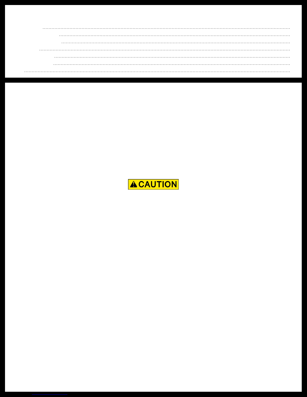
1. Locate an area on the unit’s roof to mount the external cellular antenna (Fig. 1B). The area should be
relatively flat and be located within 10 feet of the cellular gateway (Fig. 1C) mounting location. Two
small coax wires (Fig. 1A) will need to be run between the cellular antenna and the cellular gateway.
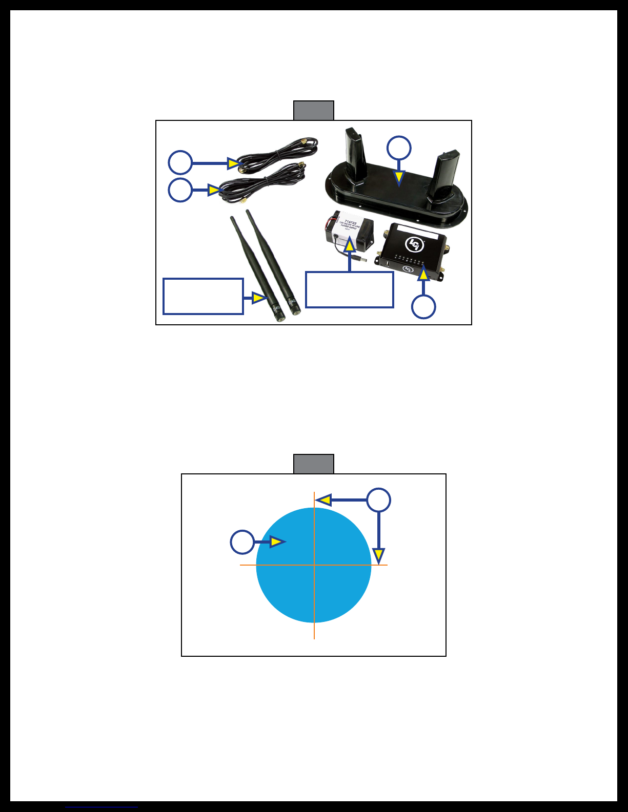
2. Position the antenna for mounting. The antenna should sit completely flat against the surface. Trace an
outline along the outer lip of the antenna.
3. Cross cut the rubber roof (Fig. 2A) orange lines. The cuts should be 1 ¼” long in each direction. Peel
the corners of the rubber roof back and drill a 1” hole (Fig. 2B, blue area) in the center of the cuts. This
is where the cables will pass from inside the unit to the cellular antenna.
NOTE: Make sure that are no wires, pipes, etc., behind the drilling area before drilling.
Fig. 2
Fig. 1
B
A
A
C
12V DC/DC
Power Supply
2.4 GHz WiFi
Antennae
B
A

Rev: 12.13.2018 Page 4 CD-0002211
4. Attach one end of the two coax cables to the coax cable female ends located underneath the external
cellular antenna (Fig. 3C). Run the opposite ends of the coax cables through the previously-drilled hole.
Make sure the coax cables reach the cellular gateway before affixing the cellular gateway permanently.
The cellular gateway (Fig. 4) should be located within 10 feet of the external cellular antenna (Fig. 3).
5. On the underside of the external cellular antenna, apply all-weather silicone sealant (Fig. 3A, green
line) around the entire outer lip. It is very important to not leave any gaps to ensure a good seal to the
mounting surface.
6. Guide the coax cable wires into the hole as the external cellular antenna is gently placed.
7. After the external cellular antenna is on the designated mounting surface, use the six provided screw
hole areas (Fig. 3B) in the bottom of the external cellular antenna, and install six #8 x 3/4” stainless
steel pan head screws through the antenna bottom and into the mounting surface. Do not
over-tighten the screws. The all-weather silicone sealant should spread out slightly as the screws
draw down the antenna.
8. An additional bead of all weather silicone sealant should be placed around the outer lip of the external
cellular antenna and on the screws to form a watertight seal. Allow all weather silicone sealant to dry
completely.
9. Secure the celluar gateway to a permanent mounting surface by installing four #8 x ¾” stainless steel
pan head screws through the provided holes (Fig. 4A) in the cellular gateway and into the permanent
mounting surface.
10. Attach the two coax cables, one cable on each side of the cellular gateway, into the ports marked
3G/4G (Fig. 4B).
11. Attach the two 2.4 GHz WiFi antennae to the corresponding ports of the cellular gateway (Fig. 5A).
Fig. 3
A
B
C C
Fig. 4 Fig. 5
B
B
A A
B
A
Rev: 12.13.2018 Page 5 CD-0002211
Power Supply
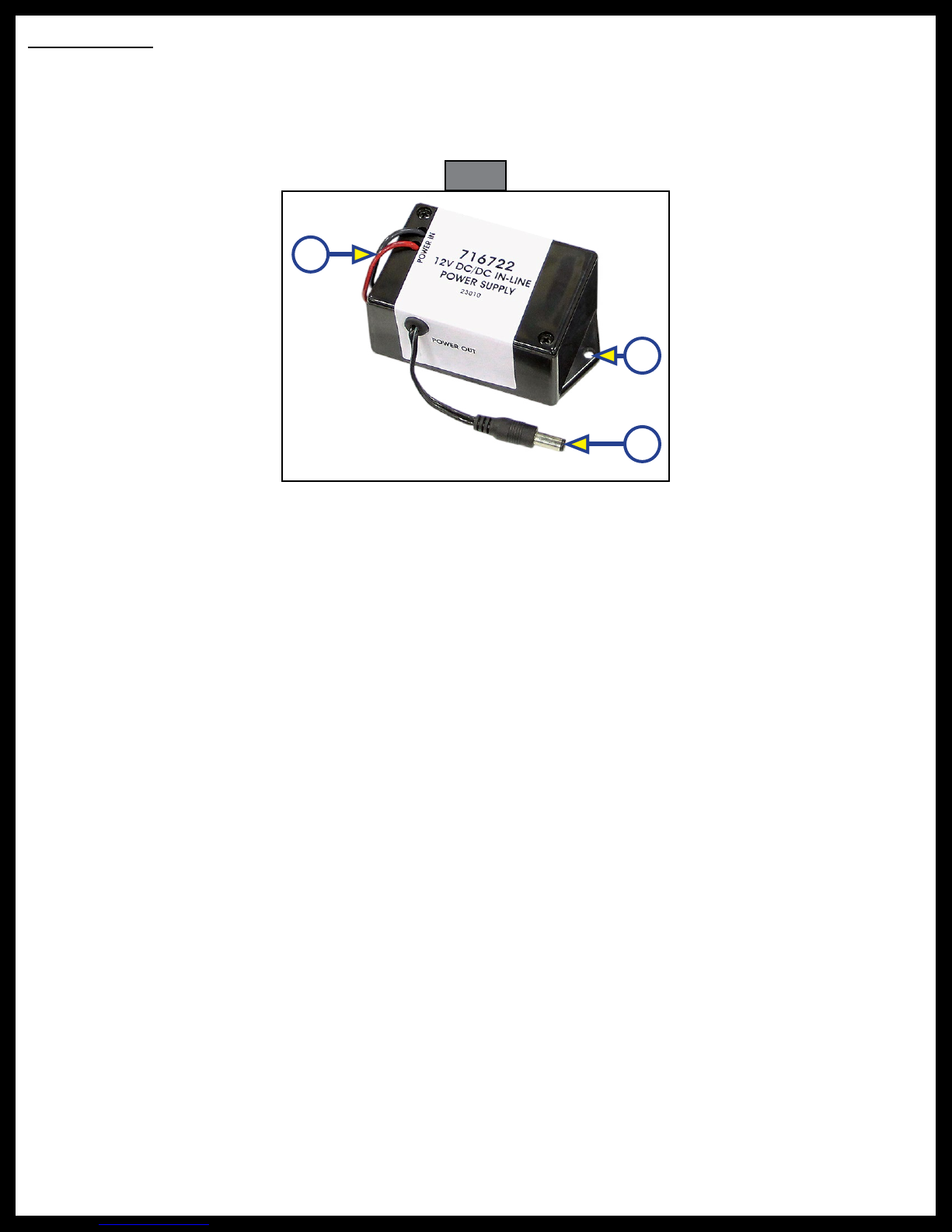
1. Connect the red and black wires (Fig. 6A) from the 12V DC/DC power supply to the unit’s power source.
2. Plug the power supply wire (Fig. 6B) into the back of the cellular gateway (Fig. 5B).
3. Secure the 12V DC/DC in-line power supply installing two #8 x ¾” stainless steel pan head screws
through the provided holes (Fig. 6C) in the power supply and into the permanent mounting surface.
Fig. 6
A
B
C

Rev: 12.13.2018 Page 6 CD-0002211
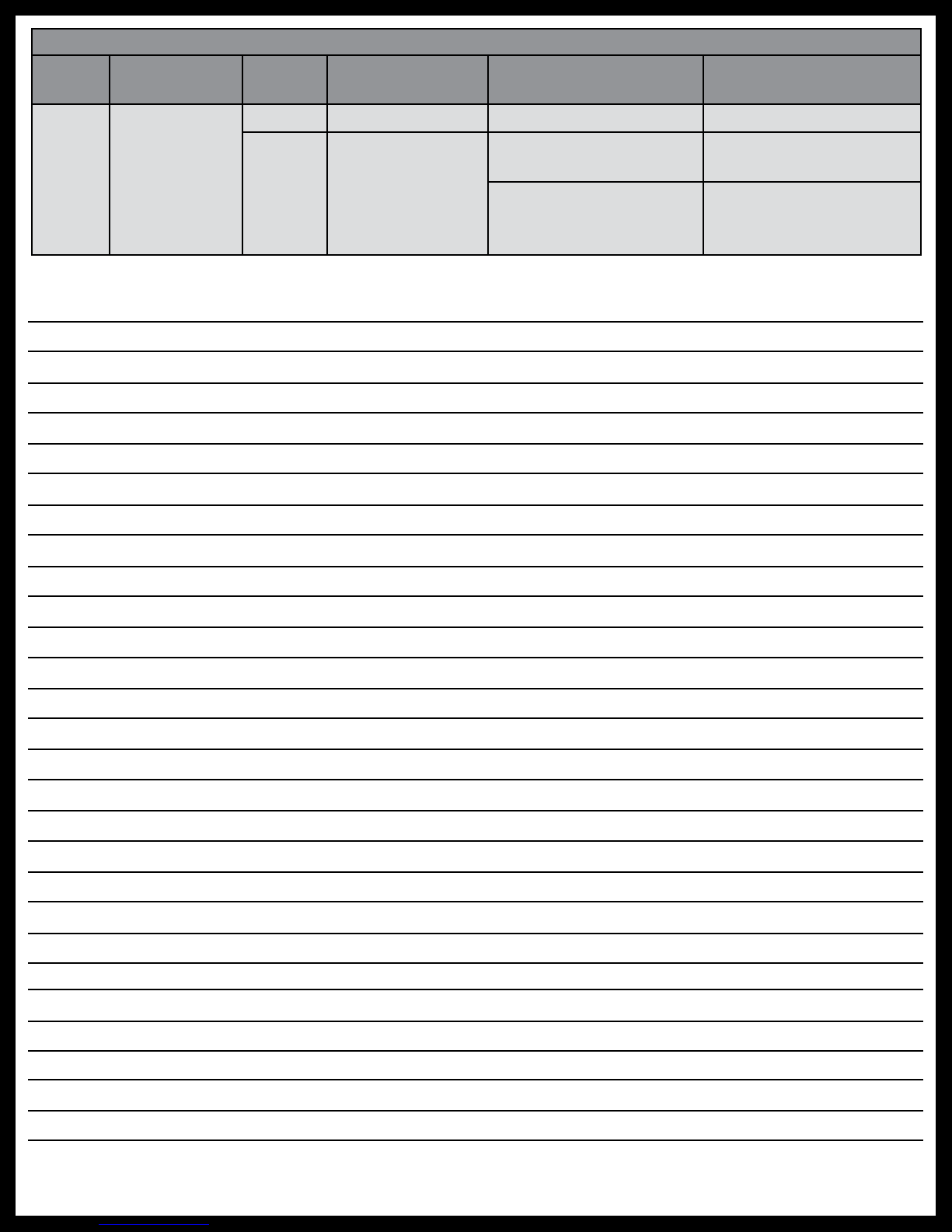
Troubleshooting
Most concerns with Hotspot can be diagnosed by
checking the indicator lights located on the top of
the cellular gateway.
LED Indicator Light Troubleshooting Chart
Letter Description LED
Color
What Is
Happening? Why? What Should Be Done?
A Power
Red
OneControl
Gateway is
powered.
No Problems. N/A
Off
OneControl
Gateway is NOT
powered.
Bad or disconnected
power cable.
RV’s battery is low or
disconnected.
Check the power source
and power connections.
B Cell
Blue
Blink (long off,
short on) Not yet connected. Check if SIM card is
installed properly.
Blink (short off,
long on)
Connected but no data
being transferred.
Cell interface being
stopped in the admin.
page. Make sure the
settings in the admin.
page are correct.
Long on followed
by fast blink
Connected and start
data transfer.
Incorrect APN entered
in the admin. page.
Make sure the settings
in the admin. page are
correct.
Fast Blink Connected and data
being transferred. N/A
Off No cell
connection. No power. Check the power
supply.
C WiFi
Blue
Solid when AP is
available, blink
on activity.
No Problems. N/A
Off No WiFi
connection.
WiFi has been disabled
in the administration
webpage.
Check the settings in
the mobile device.
D WAN
Blue Blink on activity. No Problems. N/A
Off No WAN
connection.
Not in use. Check Ethernet
connection to router.
Replace Ethernet cable
if necessary.
Bad or no Ethernet
cable connection.
ABC
D
EFG
H
Rev: 12.13.2018 Page 7 CD-0002211
Notes
LED Indicator Light Troubleshooting Chart
Letter Description LED
Color
What Is
Happening? Why? What Should Be Done?
E-H LAN
Blue Blink on activity. No Problems. N/A
Off No LAN
connection.
Bad or disconnected
Ethernet cable.
Replace Ethernet cable
if necessary.
Device on remote end
of Ethernet cable isn’t
powered.
Check power on mobile
device.

The contents of this manual are proprietary and copyright protected by Lippert Components, Inc. (“LCI”).
LCI prohibits the copying or dissemination of portions of this manual unless prior written consent from an
authorized LCI representative has been provided. Any unauthorized use shall void any applicable warranty.
The information contained in this manual is subject to change without notice and at the sole discretion of LCI.
Revised editions are available for free download from lci1.com.
Please recycle all obsolete materials.
For all concerns or questions, please contact
Lippert Components, Inc.
Table of contents
Other Lippert Components Antenna manuals

Popular Antenna manuals by other brands


RFI
RFI FSA20-67-DIN Installation

WADE Antenna, Inc.
WADE Antenna, Inc. DMX, DMXMD, DMXHD installation instructions

Norsat
Norsat WAYFARER 1.0M KU-BAND user manual

Valcom
Valcom V147-CL2 Operation and installation instructions

A.H. Systems
A.H. Systems SAS-562B Operation manual

M2 Antenna Systems
M2 Antenna Systems 2M-440XPSS manual