Teleco Magic Sat 2002A User manual

V007
INSTALLATION GUIDE
and user manual
GB

V006
Pag. 2
INDEX
TECHNICAL FEATURES ...................................................................................3
INSTALLATION TIPS .........................................................................................3
IMPORTANT NOTICE........................................................................................4
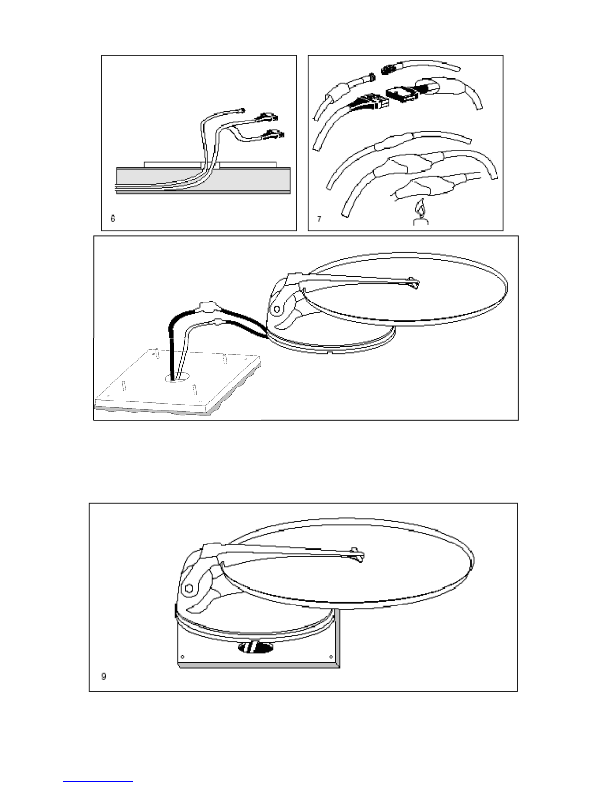
ASSEMBLY INSTRUCTIONS.............................................................................5
USER MANUAL: Magic Sat 2002A Operation System.....................................13
Satellite seeking............................................................................................13
Antenna lowering ..........................................................................................13
Programme seeking......................................................................................13
IMPORTANT INFORMATION for proper antenna pointing...........................14
AUTOMATIC SATELLITE SEARCHING.......................................................14
LOWERING THE ANTENNA ........................................................................15
ADDITIONAL OPERATIONS........................................................................ 16
Changing satellites during search .................................................................17
Sequential satellite seeking...........................................................................17
SAFETY FUNCTION.....................................................................................18
TROUBLE-SHOOTING.................................................................................18
USER'S MANUAL: For the Analogue Receiver integral with the control unit....19
Control Unit Rear Panel ................................................................................19
REMOTE CONTROL MAGIC SAT 2002A ....................................................20
ON SCREEN DISPLAY................................................................................. 22
SUBFUNCTIONS..........................................................................................23
CONNECTING WITH DIGITALI RECEIVER ....................................................30
Connecting with FALCON 12........................................................................ 30
Connecting with Mikro CI ..............................................................................31
Connecting with Mikro FTA........................................................................... 32
SPECIFICATIONS............................................................................................ 33
ESPLOSO RICAMBI..................................Errore. Il segnalibro non è definito.
RECYCLING: with a view to reducing disposal of waste
electrical and electronic equipment as much as possible,
do not throw out this end of life cycle appliance together
with other unsorted municipal waste, but make use of a
recycling centre.

V006
Pag. 3
TECHNICAL FEATURES
1) Working voltage: 12 VDC ± 15%
2) Consumption SEARCH operation: less than 5 A RECEPTION with Dish not moving: 240
mA approx.
3) Automatic Searching Time: min 20 sec - max 5 min, depending on the place you are at
and the battery status (if the battery is not fully charged, searching takes longer)
INSTALLATION TIPS
1) The MIR remote control Extension must be installed in such a way as to make sure that
it is always visible and that the remote control can therefore operate normally.
2) Do not install the Control Unit in an area subject to liquid spilling which could cause
irreparable damage to it.
3) Do no install the Control Unit in too small a space with poor ventilation, because
excessive heat could alter its good operation.
Nr. 4 Self locking
nuts Inox M6
Base plate
Outside unit
Heat-shringking tube
Control unit
Motor – Control Unit
connection cable Remote Control Extension Antenna – Control Unit
connection cable

V006
Pag. 4
IMPORTANT NOTICE
1) Due to transport reasons, Magic Sat 2002A comes packaged in two separate cartons
a) The first item contains the driving unit with all the cables and the control unit.
b) the second item only contains the dish.
It is essential to check that the dish has not been damaged during transport when the
package is opened. In particular, check the following well:
• By resting the dish edge against a flat surface (e.g. the floor or a wall) check that it
makes contact to the surface all around. If it is not so, try and make the edge level, without
denting the dish, or call our After-Sales
• After checking that everything is in order, install the dish on the driving unit as follows:
1) Temporarily connect the Control unit to the driving unit through the grey motor cable
2) Power both the Control unit and the receiver using a battery
3) Press the Red button in the remote control and extend the dish support mast
4) Press the " STOP " button in the remote control to lock the mast in a vertical position.
5) Secure the dish to the mast and screw down the four supplied screws
6) Press the " DOWN " button in the remote control and lower the antenna
7) Disconnect the Control unit, the battery and install Magic Sat 2002A on the vehicle

V006
Pag. 5
ASSEMBLY INSTRUCTIONS
1) Position the Control unit in a compartment near the TV set
2) Fix the MIR remote control Extension to a wall or your TV-set and connect it to the
Control Unit.
3) On the roof of the vehicle, choose a free area large enough to allow the antenna to
revolve (Fig. 2).
4) Install the (Grey and White) connection cables to reach the OUTDOOR UNIT
installation area..
5) Clean the roof carefully in the area the OUTSIDE UNIT is to be installed in.
6) Remembering that the OUTSIDE UNIT must be fastened as shown on Figure 3, remove
the BASE PLATE from the outside unit, unscrewing all 4 nuts. Position the base plate
as Fig.4 with the short side towards the driving direction of the vehicle (Fig. 4).

V006
Pag. 6
Driving direction of
the vehicle
Driving direction of
the vehicle
7) Clean the lower part of the BASE PLATE carefully, applying a layer of glue on the whole
surface (e.g. SIKAFLEX)
8) Fasten the Base Plate to the roof (short side towards the driving direction of the vehicle)
and fasten the 4 fastening nuts, applying silicone in the screw holes.
9) Apply a layer of silicone all around the BASE PLATE in order to make it completely
Installation with cables led through the middle of the base
10) Connect the Grey and White cables coming from inside the vehicle (Fig. 6) to both
cables of the outside unit, making them watertight using two pieces of
THERMORETRACTILE TUBE (Fig. 7).
WARNING
While performing this operation, do not pull forcefully on the cables coming from the
middle of the outside unit, in order not to risk pulling them out.

V006
Pag. 7
11) Install the OUTSIDE UNIT on the plate, bearing in mind that:
a) The proper position must be as in ( Figure 9 )
b) Coat both the base plate and the driving unit bottom ( Fig. 10 ) with a thick layer of
silicone to prevent any water infiltration. Screw in the four supplied nuts at the screws
and tighten as required ( Fig. 11 ).

V006
Pag. 8
Installation with lateral cable output
12) Fasten the OUTSIDE UNIT to the base plate. Lead both cables out of the 4 grooves
and respect the positions shown on Figure 12.
CAUTION: during this operation, do not pull either cable forcibly, as they could come out.
13) Connect both cables coming from the centre of the OUTSIDE UNIT to the extensions.
Waterproof the connectors using both pieces of heat-shrinking pipe.

V006
Pag. 9
14) Fit the cables into a fairlead skintop to the point where the cables enter the vehicle.
15) Carefully seal the fairlead skintopwhere the cables pass into the vehicle to prevent
water from coming in.

V006
Pag. 10
CONNECTIONS
16) Connect the (motor) grey cable to the MOTOR UNIT Connector and the white
(antenna) coaxial cable to the ANTENNA Connector in the Control
17) Connect the Digital Receiver (if any) to the DIGITAL RECEIVER connector.
18) Connect the MIR remote control Extension to the IR REMOTE connector in the Control
Unit
19) Connect the BLACK power supply cable of the CONTROL UNIT to the NEGATIVE
POLE of the vehicle 12 Volt battery, and the RED cable to the POSITIVE POLE + (
remember not to mix the + and - poles up ), using 2 cables of a diameter of 2.5 mm ( 5
mm2 cross-section).
20) The GREEN safety cable of the Control Unit must be connected to the consensus of
the vehicle startup console (in many cases such consensus is located on Pin 15 in the
main terminal board). In this way, whenever the motor is started, this cable receives a
positive + 12 Vdc voltage, which will automatically lower the antenna and lock all
functions of the Control Unit simultaneously (Fig.15).
Any connection made in points other than as indicated (e.g. on
the alternator) can give rise to equipment malfunction and/or damage resulting in loss of
the warranty.

V006
Pag. 11
21) Inside the Control Unit are:
a) Control ELECTRONICS of the outdoor unit motors
b) 500 Channel Analogue Receiver
c) Automatic Switch with Input for Digital Receiver

V006
Pag. 12
This technical note is to call the attention of the installation personnel to certain details of
Magic Sat 2002A installation. During installation, you must take the following precautions:
The power supply cable must come directly from the battery and be of a minimum cross-
section of 5 sq.mm. Only the Magic Sat 2002A must be connected to this cable; all the
other devices must be connected to another
The cable connecting the motor unit to the Magic Sat 2002A Control Unit must NEVER be
cut for any reason whatsoever; should the cable turn out to be too long, wind the extra part
into a coil in a free area of the vehicle. Leave a little cable in the motor unit area; should
any technical operation be required, it will make it easier to remove the motor unit.
Also, before checking its operation, we suggest you make sure that:
the outside converter (a.k.a. LNB) has been installed properly and locked into its plastic
lock nut. Remember that the outside converter has its own assembly position which must
be complied with. Otherwise you will not receive any signal. The pre-set mounting position
for the converter is along the centre line of the disk (see figure A). With this configuration,
the MagicSat Digital system works correctly in most European countries. However, if you
are in areas very far from the satellite orbital position, it might be necessary to adjust the
converter angle. In particular, if you wish to receive transmissions from the satellites Astra
19E, Astra 28E or HotBird 13E, while you find yourself in Portugal or Morocco, your
converter angle should be adjusted as shown in figure B2, while if you are in Turkey, to
receive the same satellites you should set your converter to the position B1. A chart is
attached which may help you set the ideal angle.

V006
Pag. 13
USER MANUAL: Magic Sat 2002A Operation System
Magic Sat 2002A is a fully automatic satellite pointing system, designed to point both
satellites which transmit ANALOGUE/DIGITAL signals (e.g. ASTRA or Hot Bird) and
satellites which transmit DIGITAL signals only (e.g. Astra 2). All operating information is
displayed on your TV screen when the system is
To ensure user-friendly operation, we have simplified these basic functions as
• satellite searching
• antenna lowering
• required program searching
Satellite seeking
When Magic Sat 2002A is off (Antenna down), press the Red button on the remote control
to start the searching procedure which will be completed when
Antenna lowering
When Magic Sat 2002A is on, and the antenna is up, press the (yellow) DOWN button to
bring the antenna down and switch the system off.
Programme seeking
Once the antenna has been pointed to the required satellite, radio and television stations
can be received by simply shifting programs with the remote control. To receive programs
from other satellites, you will just have to key in the number of your required program on
your remote control, or select it from the program list. MagicSat Digital will then search for
the next satellite and store the corresponding antenna position. If a digital bouquet is
requested instead of an analogue television/radio program (programs from 450 to 500),
the receiver will instruct the user on when to switch MagicSat Digital off and switch the
digital receiver on.
Thank you for having chosen our product. We wish you enjoy watching TV with Magic Sat
2002A.

V006
Pag. 14
IMPORTANT INFORMATION for proper antenna pointing
1) Before performing antenna pointing, make sure you have positioned your vehicle so the
view towards the South (where Satellite signals come from) is free from any nearby
obstacle (trees, houses, etc.). This way, the antenna will be free to receive signals
coming from the satellite.
2) It is also important to know that satellites do not transmit with the same intensity
throughout Europe, so if you are outside the reception area, your Magic Sat 2002A
search might be unsuccessful. The reception areas for each Satellite can be found on
the main magazines dealing in this line of business. Also remember that the larger the
dish, the more reception area
AUTOMATIC SATELLITE SEARCHING
1) Turn your TV set on and put it in a condition to receive signals coming from the satellite
receiver (See TV Manual).
2) Switch on the control unit by pressing the Red button on your remote control (or the
button on the front panel). The Magic Sat 2002A will also be automatically operated.
3) The following message will appear on your TV screen:
This message will remain until the antenna has identified the satellite. It tells you the name
of the satellite (e.g., Astra) which the Magic Sat Plus is looking for, and the programme
number (Programme 1) which will appear when pointing is over. Both these data are linked
to one another by a pre-storage on the receiver which has been performed in the factory in
the following order:
SATELLITE ASTRA 19°E ANNELS 1 - 62
SATELLITE TELECOM 2A 8°W CHANNELS 80 - 90

V006
Pag. 15
SATELLITE TELECOM 2B 5°W CHANNELS 91 - 98
SATELLITE HOT BIRD 13°E CHANNELS 101 - 138
SATELLITE THOR 1°W CHANNELS 180 - 200
DIGITAL BOUQUETS CHANNELS 450 - 500
4) When the antenna points at a satellite during the seeking phase, the following message
will appear on your TV screen:
If it is the right satellite (e.g. Astra), the programme images will appear on the screen after
a few seconds have elapsed (e.g., Programme 1). If it is another satellite, then the antenna
will continue to seek, and the following message will be displayed again:
5) Once the antenna has been pointed to the required satellite, radio and television
stations can be received by simply shifting programs with the remote control. To receive
programs from other satellites, you will just have to key in the number of your required
program on your remote control, or select it from the program list. MagicSat Digital will
then search for the next satellite and store the corresponding antenna position. In this
way, shifting from one satellite to the next will be immediate. If a digital bouquet is
requested instead of an analogue television/radio program (programs from 450 to 500),
the receiver will instruct the user on when to switch MagicSat Digital off and switch the
digital receiver on.
LOWERING THE ANTENNA
To bring the antenna to its horizontal position, just press your remote control DOWN
button to switch both the Receiver and Magic Sat 2002A off. During the short time it takes
for the antenna to come down, the following message will be displayed on the screen:

V006
Pag. 16
Followed by:
When the antenna reaches its horizontal position, Magic Sat 2002A will go off and TV
messages will disappear. Should you forget to lower the antenna before starting up with
your road vehicle, don't worry: the moment you turn the engine ignition key, a special
safety circuit will lower the antenna automatically, keeping it locked in place as long as the
vehicle moves. This however is possible only if the special Green cable has been
connected to the ignition key at the time
N.B. Because of this safety function, remember that if you decide to turn the engine on in
order to charge the batteries of the vehicle, the Magic SatDIGITAL will automatically bring
the antenna down; as long as the engine is running, it will not be possible to perform
searching.
ADDITIONAL OPERATIONS
1) With the antenna pointed to a satellite, the Control unit may be turned off (by pressing
the Red push-button) without having to lower the antenna. In this case, the total
consumption by the system MAGIC SAT 2002A will be cut down to approximately 240
mA. To power the Control unit back on, just press the Red push-button on the remote
control once again.
2) If the antenna is in motion, the red push-button WILL NOT be working to prevent the
Control unit being switched off which would make satellite searching ineffective.
3) In the event that Magic Sat 2002A does not find the selected satellite, it will stop the
antenna at the end of its stroke (either all the way out or all the way in) and show the
message " No satellite " on the TV screen and " NSA" on the FP3412. If this happens,
the antenna can be lowered by pressing the DOWN push-button or a program
transmitted by another satellite can be selected.

V006
Pag. 17
OPERATIONS FOR THOSE WITH GREATER EXPERTIS
Changing satellites during search
The Magic Sat Plus always starts its automatic search by examining the satellite which
transmits the last programme chosen before turning the system off (e.g. Astra, Channel 1).
Should you wish to launch an automatic search for another satellite, proceed as follows:
• Press the RED key on the remote control to swhitch on the system.
• Press the STOP key to stop the antenna temporarily (the words "Search suspended" will
be displayed on the TV set)
• Choose the new channel transmitted by the satellite you want (e.g. Channel 101, Hot
Bird)
• After a few seconds, the antenna will start searching again and will stop on the new
satellite (Hot Bird).
WARNING: if the antenna is stopped with the STOP button, this can only be restarted if a
programme transmitted by another satellite is selected.
Sequential satellite seeking
This kind of search is used only when you are at the edge of the reception area, where
signals are weaker, and only if Automatic Search has failed.
1 Turn the system on with the Red key
2 Interrupt the search pressing the STOP key
3 Press the MENU key
4 Choose CONFIGURATION
5 Choose SAT SEARCH
6 Choose SAT SEARCH: SEQUENTIAL using the key
7 Exit the MENU (See the Analogue Receiver instruction Manual)
8 Choose the programme you want (e.g.: 1)
At this point, the Magic Sat 2002A will start to search for the signal of the programme you
have chosen. When the antenna points at a satellite which transmits this signal, it will stop
and the following message will be displayed:
Should the programme appearing on the TV set be the one that interests you, press the
OK key; otherwise, press the NEXT key to make the antenna search for another Satellite
which transmits the programme you want. The SEQUENTIAL SEARCH for the chosen
channel (e.g. Channel 1) could fail too. In this case, press the Down key again to lower the
antenna and turn the system off. Since satellites transmit some channels with high power
and others with lower power, in case of failure, you would do best to try another search
changing the number
1) Press the Red key to turn on
2) Press the STOP key to interrupt the search

V006
Pag. 18
3) Choose a different channel number (e.g. 15), still however belonging to the group
transmitted by the satellite you want (in this case, Astra)
4) After a few seconds, Magic Sat 2002A will start seeking for the chosen channel
(channel 15) and will repeat the steps listed above.
SAFETY FUNCTION
If, for any reason (trees, ice, etc.), the antenna is not able to move freely during the
operation, it will stop at once and the following message will be displayed:
After having verified the reason for the blockage, press the DOWN key and then remove
the cause.
TIPS on the best use of Magic Sat 2002A
When you park your vehicle, make sure that:
1) The view towards the South is free of any nearby obstacles. Any obstacle (trees or
buildings) between the satellite and the antenna prevent proper
2) No obstacle (for example trees) is too near your antenna, preventing it from moving
freely. No metal or glass wall is very near (about 5 m) the antenna, since this would act
as a mirror for satellite signals and could induce the antenna to point towards it.
3) In case of snow or ice actuating the Magic Sat 2002A free it in order to avoid wasting
battery power in order to lift it.
4) If you decide to turn the engine of your vehicle on in order to re-charge its batteries, with
the safety cable connected to the ignition key, the antenna, if lifted, will come down
automatically and it will not be possible to lift it again as long as the engine is running.
5) Make sure that your batteries are always sufficiently charged, since, if the voltage falls
below 10 Volts, the Magic Sat Digita electronic safety circuit will prevent the antenna
from rising.
6) Should you use 12 Volt feeders instead of batteries in order to feed the Magic Sat
2002A, be careful to use high quality stabilized feeders with a supplied power of at least
10A. At all costs, avoid using low quality, non stabilized battery feeders.
TROUBLE-SHOOTING
If the Magic Sat 2002A has not found the satellite after a complete search,
:
a) Is the view towards the South free from any obstacle?
b) Is the place you are at within the reception area of the satellite you have chosen?
c) Is the cable connecting the LNB to the antenna firmly fastened? It could have been
ripped off or come loose because of contact with an unexpected
d) Are all the connections on the Control Unit properly set up?

V006
Pag. 19
If the antenna has stopped after performing pointing, but neither messages nor images
appear on the screen:
a) Is the SCART cable connected?
b) If the TV set is not connected by a SCART cable, but is connected by a COAX cable to
the TV socket, have you chosen the right programme on
If the antenna does not move when you press the Red push-button, check the
a) Are the RED and BLACK cables properly connected to the battery? The RED cable
must be on the + pole, the BLACK cable on the - pole.
b) Should you have mixed up the cables, first disconnect them, replace the safety fuse on
the bottom of the Control Unit using a similar one (10 A), then re-connect the RED and
BLACK cables properly to the battery.
c) Is the engine on your vehicle running? Turn it off, since this means the safety system
which keeps the antenna down is operating.
USER'S MANUAL: For the Analogue Receiver integral with the control
unit
Control Unit Front Panel
1) Transparent front panel with 3-digit display and remote control sensor.
2) Channel selection keys.
3) Instrument on/off key. When the instrument is off, a horizontal line is displayed.
Control Unit Rear Panel

V006
Pag. 20
1) Connection cables to the 12V Battery
2) Connector to connect a Digital Receiver to Magic Sat 2002A
3) Connector to connect to the Magic Sat 2002A LNB
4) Connector to connect the (optional) FP3412 control extension
5) Connector to connect the Magic Sat 2002A Motor cable
6) SCART outlet for connection to VCR or DECODER units
7) SCART outlet for TV connection
8) AUDIO R-L outlets for HI-FI stereo connection
9) Connector to connect the control unit to a TV-set not equipped with any SCART outlets.
The Output channel is set to CH 21 and can be tuned to anything from 21 to 69, as you
may choose, using the remote control.
10) Connector to connect one terrestrial antenna
11) Connector to connect the MIR remote control extension (supplied).
REMOTE CONTROL MAGIC SAT 2002A
This remote control can be used to control all the functions of Magic Sat 2002A and the
Analogue Receiver built in the Control
Main functions
Control Unit instrument is off, a horizontal line remains lit on
the display. When the receiver is switched on, the program
Analogue Receiver Program up/down
Used to directly enter the number of the
program that you wish to select.
Volume control. A value in the range 0/100 will be visible on
the TV screen at the time of operation. During this period
alterations can be made to the sound
Bass control. A value in the range -15/+15 will be visible on
the TV screen at the time of operation. During this period
alterations can be made to the sound
Treble control. A value in the range - 15/+15 will be visible on
the TV screen at the time of operation. During this period
alterations can be made to the sound
MUTE control. Press to turn off sound. The TV screen will
show AUDIO MUTO, the display will show MUT.
SPATIAL STEREO selection. By pressing this key you will
increase the stereo effect. SUONO SPAZIALE (SPACE SOUND) will be displayed on
Table of contents
Other Teleco Antenna manuals

Teleco
Teleco Flat Sat Classic Smart 85 Assembly instructions

Teleco
Teleco Motostat digimatic 65 Assembly instructions

Teleco
Teleco FlatSat Easy Smart 85 Assembly instructions

Teleco
Teleco Motosat65 Assembly instructions

Teleco
Teleco Flat Sat Elegance Smart 50 User manual

Teleco
Teleco TeleSat S65 Assembly instructions

Teleco
Teleco Flat Sat Classic Smart 85 Assembly instructions

Teleco
Teleco Flatsat Classic Easy Assembly instructions

Teleco
Teleco VoyagerG3 65 Assembly instructions