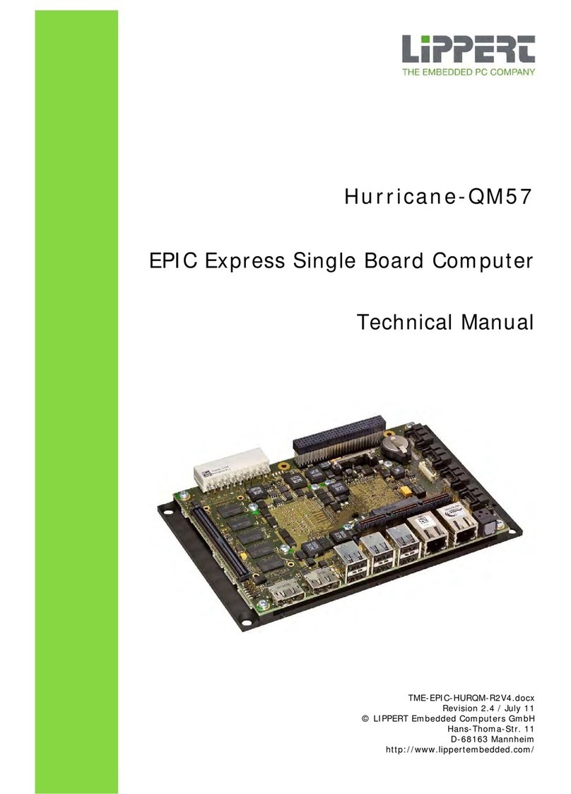
LiPPERT Embedded Hurricane-PM User manual

TME-EPIC-HURPM-R1V5.doc
Revision 1.5/ May 08
©LIPPERT Embedded Computers GmbH
Hans-Thoma-Str. 11
D-68163 Mannheim
http://www.lippertembedded.com/
Hurricane-PM
EPIC Single Board Computer
Technical Manual

TME-EPIC-HURPM-R1V5.doc Rev 1.5
Technical Manual Hurricane-PM
LiPPERT Document: TME-EPIC-HURPM-R1V5.doc Revision 1.5
Copyright © 2007-2008 LiPPERT Embedded Computers GmbH, All rights reserved
Contents and specifications within this manual are subject of change without notice.
Trademarks
MS-DOS, Windows, Windows 95, Windows 98, Windows NT and Windows XP are trademarks of
Microsoft Corporation. PS/2 is a trademark of International Business Machines, Inc. Intel is a
trademark of Intel Corporation. Geode is a trademark of Advanced Micro Devices, Inc. M-Systems
and DiskOnChip are trademarks or registered trademarks of M-Systems Flash Disk Pioneers, Ltd.
PC/104 is a registered trademark of the PC/104 Consortium. Mozilla and Firefox are registered
trademarks of the Mozilla Foundation. EPIC (Embedded Platform for Industrial Computing) is a
trademark of Octagon Systems, Micro/sys, VersaLogic, WinSystems, and Ampro Computer
Corporations.
All other trademarks appearing in this document are the property of their respective owners.

TME-EPIC-HURPM-R1V5.doc Rev 1.5 i
Table of Contents
0H1. Overview 116H1
1H1.1 Introduction .......................................................................................... 117H1
2HFeatures................................................................................................118H1
3HBlock Diagram........................................................................................119H2
4H1.2 Ordering Information............................................................................. 120H3
5HHurricane-PM Models...............................................................................121H3
6HCable Sets and Accessories ......................................................................122H3
7H1.3 Specifications ........................................................................................ 123H4
8HElectrical Specifications............................................................................124H4
9HEnvironmental Specifications....................................................................125H4
10HMTBF ....................................................................................................126H4
11HMechanical.............................................................................................127H4
12H2. Getting Started 128H5
13H2.1 Connector Locations .............................................................................. 129H5
14HFront ....................................................................................................130H5
15HTop.......................................................................................................131H6
16HBottom..................................................................................................132H7
17H2.2 On Board LED Indicators........................................................................ 133H8
18H2.3 Hardware Setup..................................................................................... 134H9
19H3. Module Description 135H10
20H3.1 Processor............................................................................................... 136H10
21H3.2 Northbridge ........................................................................................... 137H10
22H3.3 Southbridge........................................................................................... 138H11
23H3.4 Watchdog .............................................................................................. 139H11
24H3.5 Graphics Controller................................................................................ 140H13
25HVGA Connector..................................................................................... 141H14
26HLVDS .................................................................................................. 142H14
27HLVDS Connector ................................................................................... 143H14
28HDisplay Backlight Connector ................................................................... 144H15
29HDisplay Voltage Selector ........................................................................ 145H15

TME-EPIC-HURPM-R1V5.doc Rev 1.5 ii
30H3.6 Ethernet Controller 1 ............................................................................. 146H16
31H10/100Mbit Ethernet/USB Combi Connector.............................................. 147H16
32H3.7 Ethernet Controller 2 ............................................................................. 148H17
33H10/100Mbit Ethernet/USB Combi Connector.............................................. 149H17
34H3.8 On Board Power Supply ......................................................................... 150H18
35HPower Connector (standard usage and +5V-only)...................................... 151H18
36HBackup Battery..................................................................................... 152H18
37H3.9 EIDE Port............................................................................................... 153H19
38HEIDE Connector.................................................................................... 154H19
39H3.10 PS/2 Keyboard and Mouse Interface ..................................................... 155H19
40HPS/2 Connectors................................................................................... 156H19
41H3.11 On Board USB for uDOC ......................................................................... 157H20
42HUSB Connector..................................................................................... 158H20
43H3.12 Serial Ports............................................................................................ 159H21
44HCOM1 Connector................................................................................... 160H21
45HCOM2 Connector................................................................................... 161H22
46HRS485-Termination Jumpers .................................................................. 162H22
47H3.13 IrDA Interface ....................................................................................... 163H23
48HIrDA Connector .................................................................................... 164H23
49H3.14 Parallel Port LPT1 .................................................................................. 165H23
50HLPT1 Connector.................................................................................... 166H24
51H3.15 Audio Interface...................................................................................... 167H25
52HFront Audio Connector........................................................................... 168H25
53HOn Board Audio Connector ..................................................................... 169H25
54H3.16 System Panel Connector ........................................................................ 170H26
55HExternal Power-Button........................................................................... 171H26
56HReset-In Signal .................................................................................... 172H26
57HExternal Battery ................................................................................... 173H26
58HWatchdog Output.................................................................................. 174H27
59HPower LED Output................................................................................. 175H27
60HHDD LED Output................................................................................... 176H27
61H3.17 CPU Fan Supply...................................................................................... 177H28
62H3.18 Supervisory Connector........................................................................... 178H28
63H3.19 PC/104-Plus Bus Interface .................................................................... 179H29

TME-EPIC-HURPM-R1V5.doc Rev 1.5 iii
64H3.20 PC/104 Bus Interface............................................................................ 180H30
65HPC/104 Bus Connector........................................................................... 181H30
66H4. Using the Module 182H31
67H4.1 BIOS ...................................................................................................... 183H31
68HSetup.................................................................................................. 184H31
69HInitialize BIOS at first startup ................................................................. 185H31
70HBooting from alternative device .............................................................. 186H31
71HReload default BIOS values .................................................................... 187H31
72HBIOS Setup Overview............................................................................ 188H31
73H5. Address Maps 189H38
74HMemory Address Map ............................................................................ 190H38
75HI/O Address Map................................................................................... 191H39
76HInterrupts............................................................................................ 192H40
77HDMA Channels...................................................................................... 193H41
78HAppendix A, Trouble Shooting 194HA
79HAppendix B, Contact Information 195HB
80HAppendix C, Getting Help 196HC
81HAppendix D, Further Resources 197HC
82HAppendix E, Revision History 198HE

TME-EPIC-HURPM-R1V5.doc Rev 1.5 iv
List of figures
83HFigure 1: Block diagram of the Hurricane-PM....................................................................................199H2
84HFigure 2: Front plate connectors .....................................................................................................200H5
85HFigure 3: Connectors on top of the module.......................................................................................201H6
86HFigure 4: Watchdog circuit........................................................................................................... 202H12
87HFigure 5: BIOS Main screen.......................................................................................................... 203H31
88HFigure 6: BIOS Standard features setup......................................................................................... 204H32
89HFigure 7: BIOS Advanced setup .................................................................................................... 205H32
90HFigure 8: BIOS CPU features ........................................................................................................ 206H32
91HFigure 9: BIOS Advanced chipset features setup (1) ........................................................................ 207H33
92HFigure 10: BIOS Advanced chipset features (2), LVDS panel support.................................................. 208H33
93HFigure 11: BIOS Integrated peripherals, overview ........................................................................... 209H33
94HFigure 12: BIOS Integrated IDE.................................................................................................... 210H34
95HFigure 13: BIOS Integrated Audio................................................................................................. 211H34
96HFigure 14: BIOS Integrated serial ports .........................................................................................212H34
97HFigure 15: BIOS Integrated USB device ......................................................................................... 213H35
98HFigure 16: BIOS Special features setup..........................................................................................214H35
99HFigure 17: BIOS Power management setup .................................................................................... 215H36
100HFigure 18: BIOS PnP/PCI Configuration.......................................................................................... 216H36
101HFigure 19: BIOS CPU frequency and voltage control......................................................................... 217H37

TME-EPIC-HURPM-R1V5.doc Rev 1.5 Page 1 of 41
1. Overview
1.1 Introduction
The Hurricane-PM is a high-performance EPIC board based on Intel®Pentium M processor, having
only small power requirements. The board integrates all peripherals of an embedded PC on a small
115 mm x 165 mm (4.5” x 6.5”) printed circuit board. Together with the Intel® ICH4 southbridge
and a Super I/O chip, the board is a complete PC. There is graphics controller with VGA and LVDS
adapters, which connects many sorts of display terminals. Backlighting is provided for LCD modules.
Two fast 10/100BaseT Ethernet ports, two RS232/RS422/RS485 serial ports, and six USB 2.0 host
ports handle the communication with external devices. There are PS/2 connectors for keyboard and
mouse as well as a parallel printer port available. Sound I/O according to AC97 is supported, too. An
IDE ATA100 adapter allows connection of hard disk or CD drives. Applications that require non-
moving storage can use the built-in µDOC interface and connect a suitable FlashDrive to it.
The Hurricane-PM is powered by a 10 pin ATX supply connector and supports ACPI, advanced power
management and PCI power management. Additionally, digital and analog I/O is available for the
application.
System expansion is easily done using the PC/104-Plus or the PC/104 connectors and adding
suitable specialized I/O modules.
Features
The Hurricane-PM board is an embedded industrial computer based on Intel® Pentium M and Intel®
855GME chipset. It provides standard legacy I/O devices for industrial applications.
•PC/104 Plus connectors for peripherals
•2 independent Ethernet 10/100BaseT interfaces
•6 x USB 2.0 (incl. 1 x uDOC header for USB 2.0 flash drives)
•2 x RS232/RS485 software selectable serial ports
•EIDE (ATA100) on IDC44
•Analog VGA
•LVDS for displays, either single channel 18 bits or dual channel 2x18 bits, with backlight
power
•AC97 Audio with line-in, line-out, mic-in and SPDIF
•Parallel port
•PS/2 keyboard/mouse support
•10 pin ATX Power supply

TME-EPIC-HURPM-R1V5.doc Rev 1.5 Page 2 of 41
Block Diagram
Figure 1: Block diagram of the Hurricane-PM

TME-EPIC-HURPM-R1V5.doc Rev 1.5 Page 3 of 41
1.2 Ordering Information
Hurricane-PM Models
Order number Description
810-0005-10 CPU board with Intel Celeron M (0.6GHz, 512kB L2 cache, 400MHz FSB)
Operating temp. range: -20°C .. +60°C
810-0002-10 CPU board with Intel Celeron M 373 (1.0 GHz, 512kB L2 cache, 400 MHz FSB)
Operating temp. range: -20°C .. +60°C
810-0003-10 CPU board with Intel Pentium M 738 (1.4 GHz, 2MB L2 cache, 400 MHz FSB).
Operating temp. range: -20°C .. +60°C
810-0004-10 CPU board with Intel Pentium M 745 (1.8 GHz, 2MB L2 cache, 400 MHz FSB).
Operating temp. range: -20°C .. +60°C
910-0005-10 CPU board with Intel Celeron M (0.6GHz, 512kB L2 cache, 400MHz FSB)
Operating temp. range: -40°C .. +85°C
910-0002-10 CPU board with Intel Celeron M 373 (1.0 GHz, 512kB L2 cache, 400 MHz FSB)
Operating temp. range: -40°C .. +85°C
Cable Sets and Accessories
Order number Description
863-0013-10 Cable set for Hurricane-PM: COM, IDE (44 pin, 2mm), cable adapter 2.5" > 3.5",
adapter 3.5" > 2.5"
869-0007-10 Windows XP Embedded Board Support Package for the Hurricane-PM.
865-0015-10 Heat sink, passive, Hurricane-PM
865-0016-10 Heat sink, active, Hurricane-PM

TME-EPIC-HURPM-R1V5.doc Rev 1.5 Page 4 of 41
1.3 Specifications
Electrical Specifications
Supply voltage + 5V DC
Rise time < 5 ms
Supply voltage ripple ± 5 %
Supply current
0.6GHz Celeron M
810-0005-10
910-0005-10
max. 2.8 A, depending on usage and operating system
typ. 1.9 A (Windows XP idle mode)
typ. 2.1 A (MS-DOS)
1.0GHz Celeron M
810-0002-10
810-0002-10
max. 3.2 A, depending on usage and operating system
typ. 2.0 A (Windows XP idle mode)
typ. 2.4 A (MS-DOS)
1.4GHz Pentium M
810-0003-10 max. 3,8 A, depending on usage and operating system
typ. 2.2 A (Windows XP idle mode)
typ. 3.1 A (MS-DOS)
1.8GHz Pentium M
810-0004-10 max. 5.7 A, depending on usage and operating system
typ. 2.6 A (Windows XP idle mode)
typ. 3.9 A (MS-DOS)
Inrush current 3 A peak
Environmental Specifications
Temperature range -20 … 60 °C (standard version)
-40 … 85 °C (extended version)
Storage temperature -40 … 85 °C
Temperature change max. 10K / 30 minutes
Humidity (relative) 10 … 90 % (non-condensing)
Pressure 450 … 1100 hPa
MTBF
MTBF at 25°C 153.939 hours
Mechanical
Dimensions (L x W) 115 mm x 165 mm (4.53"- x 6.5")
Height 50 mm
Weight 300 g
Mounting 4 mounting holes for PCB
4 mounting holes for PC/104 Plus
Note It is strongly recommend using plastic spacers instead of metal spacers to
mount the board. With metal spacers, there is a possible danger to create
a short circuit with the components located around the mounting holes.
This can damage the board!

TME-EPIC-HURPM-R1V5.doc Rev 1.5 Page 5 of 41
2. Getting Started
2.1 Connector Locations
Front
Figure 2: Front plate connectors

TME-EPIC-HURPM-R1V5.doc Rev 1.5 Page 6 of 41
Top
Figure 3: Connectors on top of the module

TME-EPIC-HURPM-R1V5.doc Rev 1.5 Page 7 of 41
Bottom
LVDS
Backlight
Supervisory

TME-EPIC-HURPM-R1V5.doc Rev 1.5 Page 8 of 41
2.2 On Board LED Indicators
To facilitate problem solving, the Hurricane-PM provides LED indicators for the following conditions:
LED Name Function
1 HDD PATA accesses
2 WTD
Watchdog has been activated
3 SBY
+5V power ok
4 PWRGD
onboard Power Supplies are working
5 LIVE
Hurricane-PM was started
Watchdog Hard disk
Standby
Power good
Life

TME-EPIC-HURPM-R1V5.doc Rev 1.5 Page 9 of 41
2.3 Hardware Setup
Installing the Hurricane-PM is very straightforward. Unpack the board observing the usual
electrostatic discharge (ESD) precautions.
Caution
Before you touch the board, make sure that you have discharged yourself
and your gear towards a grounded terminal. Damages due to ESD are usually
not immediately visible and will only show up later as failures in the field.
If applicable, mount your cooling device.
Caution
Never operate the Hurricane-PM without suitable cooling devices. Failing this
could destroy the Hurricane-PM.
Connect a display monitor to the VGA connector and keyboard and mouse PS/2 or to USB
connectors. Add a suitable hard drive and/or a CD drive to the configuration.
Caution
Never connect or disconnect peripherals like HDD's while the board's power
supply is connected and switched on!
Connect a standard ATX supply and switch on the power.
The display shows the BIOS messages. If you want to change the standard BIOS settings, press the
<DEL> key to enter the BIOS menu. See BIOS chapter for more details.
If you need to load the BIOS default values, press the <Insert> key during startup. This forces the
BIOS to load the factory settings from FlashPROM.
The Hurricane-PM boots from CD drives, USB floppy, USB stick, harddisk or network. Provided that
any of these is connected and contains a valid operating system image, the display then shows the
boot screen of your operating system.
Note
Not all USB devices are suitable to boot the Hurricane-PM from.
If there are problems, please use another device from another manufacturer.

TME-EPIC-HURPM-R1V5.doc Rev 1.5 Page 10 of 41
3. Module Description
3.1 Processor
IntelP
®
PPentiumP
®
PM Processor, 600 MHz … 1.8 GHz
The Intel Pentium M processor is a high performance, low power mobile processor with several
micro-architectural enhancements over existing Intel mobile processors.
Some of the key features of this processor are:
•Supports Intel Architecture with Dynamic Execution
•High performance, low-power core
•On-die, primary 32-kbyte instruction cache and 32-kbyte write-back data cache
•On-die, 1-MByte second level cache with Advanced Transfer Cache Architecture
•Advanced Branch Prediction and Data Prefetch Logic
•Streaming SIMD Extensions 2 (SSE2)
•400-MHz, Source-Synchronous processor system bus
•Advanced Power Management features including Enhanced IntelP
®
PSpeedStepP
®
Ptechnology
•Micro-FCPGA and Micro-FCBGA packaging technologies
The Intel Pentium M processor is manufactured on Intel’s advanced 0.13-micron process technology
with copper interconnect. The processor maintains support for MMX™ technology and Internet
Streaming SIMD instructions and full compatibility with IA-32 software. The high performance core
features architectural innovations like Micro-op Fusion and Advanced Stack Management that reduce
the number of micro-ops handled by the processor. This results in more efficient scheduling and
better performance at lower power. The on-die 32-kB Level 1 instruction and data caches and the 1-
MB Level 2 cache with Advanced Transfer Cache Architecture enable significant performance
improvement over existing mobile processors. The processor also features a very advanced branch
prediction architecture that significantly reduces the number of mispredicted branches. The
processor’s Data Prefetch Logic speculatively fetches data to the L2 cache before an L1 cache
requests occurs, resulting in reduced bus cycle penalties and improved performance.
The Streaming SIMD Extensions 2 (SSE2) enables break-through levels of performance in
multimedia applications including 3-D graphics, video decoding/encoding, and speech recognition.
The new packed double-precision floating-point instructions enhance performance for applications
that require greater range and precision, including scientific and engineering applications and
advanced 3-D geometry techniques, such as ray tracing.
3.2 Northbridge
Intel®i82855GME with Chipset Graphics and Memory Controller Hub (GMCH)
•Processor/Host Bus at 400 MHz
•Memory System PC1600/PC2100/PC2700 DDR SDRAM (200/266/333MHz)
•System Interrupts Intel 8259
•Video Stream Decoder with improved hardware motion compensation for MPEG2 and
Software DVD at 60 Fields/second and 30 frames/second full screen, encoding at low CPU
utilization
•Analog display support, 350-MHz integrated 24-bit RAMDAC that can drive a standard
progressive scan analog monitor with pixel resolution up to 1600 × 1200 at 85 Hz and up to
2048 × 1536 at 75 Hz
•Dual independent pipe support
oConcurrent: Different images and native display timings on each display device

TME-EPIC-HURPM-R1V5.doc Rev 1.5 Page 11 of 41
oSimultaneous: Same images and native display timings on each display device
•Dedicated LFP (local flat panel) LVDS interface, Single- or dual-channel LVDS panel support
up to UXGA panel resolution with frequency range from 25 MHz to 112 MHz (single
channel/dual channel), Supports data format up to 24 bpp
•Internal Graphics Features, 2D/3D graphics engine
For detailed information, please use the Intel®i82855GME datasheet.
3.3 Southbridge
Intel®i82801DB I/O Controller Hub 4 (ICH4)
The ICH4 provides extensive I/O support. Functions and capabilities include i.e.:
•PCI Local Bus Specification, Revision 2.2-compliant with support for 33 MHz PCI operations.
•ACPI Power Management Logic Support
•Enhanced DMA controller, Interrupt controller, and timer functions
•Integrated IDE controller supports Ultra ATA100/66/33
•USB host interface with support for 6 USB ports; 3 UHCI host controllers; 1 EHCI high-
speed USB 2.0 Host controller
•Integrated LAN controller
•System Management Bus (SMBus) Specification, Version 2.0 with additional support for I2C
devices
•Supports Audio Codec ’97, Revision 2.3 specification (a.k.a., AC ’97 Component
Specification, Revision 2.3) Link for Audio and Telephony codecs (up to seven channels)
•Low Pin Count (LPC) interface
3.4 Watchdog
The watchdog timer consists of an 8-bit counter and three registers: timeout register (WDTO), mask
register (WDMSK) and status register (WDST). The counter is an 8-bit down counter that is clocked
every minute or second and is used for the timeout period countdown. The WDTO register holds the
programmable timeout, which is the period of inactivity after which the watchdog timer prompts the
system (1 to 255 minutes or seconds). The WDMSK register determines which system events are
enabled as watchdog timer trigger events to restart the countdown. The WDST register holds the
watchdog timer status bit that reflects the value of the WDO pin and indicates that the timeout
period has expired. In addition, it sets the time unit (minutes or seconds). The figure shows the
functionality of the watchdog timer.
Note
The watchdog signal remains unchanged up to the next power cycle

TME-EPIC-HURPM-R1V5.doc Rev 1.5 Page 12 of 41
Figure 4: Watchdog circuit
The following registers of the Super I/O are used for controlling the watchdog function:
Index register (0x4e) Data register (0x4f) Action
0x07 0x0a Select functional group 10 (Watchdog)
0x60 0x03 Set WDT base address bits (15-8)
0x61 0x70 Set WDT base address bits (7-0)
0x30 0x01 Activate Watchdog
The following table shows the registers of the WATCHDOG Timer (WDT):
Register Description
0x370 WATCHDOG Timeout Register (WDTO)
This register holds the programmable timeout period, which is between 1 and
255 minutes or seconds. Writing to this register de-asserts the WDO output
and sets the WDO status bit to 1 (inactive). Additionally, writing to this
register is interpreted as a command for starting or stopping the WATCHDOG
Timer, according to the data written. If a non-zero value is written, the timer
is activated (countdown starts). If a non-zero value is written when the
counter is running, the timer is immediately reloaded with the new value and
starts counting down from the new value. If 00h is written, the timer and its
outputs are deactivated.
0x371 WATCHDOG Mask Register (WDMSK)
This register is used to determine which system events (IRQ) are enabled as
WATCHDOG Timer trigger events. An enabled IRQ event becomes a trigger
event that causes the timer to reload the WDTO and restart the countdown.
0x372 WATCHDOG Status Register (WDST)
This register holds the WATCHDOG Timer status, which reflects the value of
the WDO pin and indicates that the timeout period has expired.

TME-EPIC-HURPM-R1V5.doc Rev 1.5 Page 13 of 41
Program example:
Please check the Super-I/O's datasheet (Winbond, PC87364) for details about the operation and the
signals.
3.5 Graphics Controller
The GMCH IGD provides a highly integrated graphics accelerator delivering high performance 2D,
3D, and video capabilities. With its interfaces to UMA using a DVMT configuration, an analog display,
a LVDS port, and two digital display ports (e.g. flat panel), the GMCH can provide a complete
graphics solution.
The GMCH also provides 2D hardware acceleration for block transfers of data (BLTs). The BLT engine
provides the ability to copy a source block of data to a destination and perform raster operations
(e.g., ROP1, ROP2, and ROP3) on the data using a pattern, and/or another destination. Performing
these common tasks in hardware reduces CPU load, and thus improves performance. High bandwidth
access to data is provided through the system memory interface. The GMCH uses tiling architecture
to increase system memory efficiency and thus maximize effective rendering bandwidth. The Intel
855GME GMCH also improves 3D performance and quality with 3D zone rendering technology.
The GMCH has four display ports, one analog and three digital. These provide support for a
progressive scan analog monitor, a dedicated dual channel LVDS LCD panel, and two DVO devices.
The Graphics Controller uses an integrated 350-MHz, 24-bit RAMDAC with maximum pixel resolution
support up to 1600 × 1200 at 85 Hz and up to 2048 × 1536 at 72 Hz.
void SetWatchdog(uint8 time)
{
uint8 temp, timer;
outportb(0x4E, 7); // select functional group 7
outportb(0x4F, 10); // select functional group 10
outportb(0x4E, 0x60); // select WD base address (bits 15...8)
outportb(0x4F, 3); // set address bits 15...8 to 3
outportb(0x4E, 0x60); // select WD base address (bits 7...0)
outportb(0x4F, 112); // set address bits 7...0 to 112 (70h)
outportb(0x4E, 0x30); // select enable/disable register...
outportb(0x4F, 1); // ...and enable watchdog
outportb(0x371, 1); // define keyboard interrupt as trigger event
outportb(0x372, 0x80); // set unit time to seconds
outportb(0x372, 0x84);
outportb(0x370, time); // set time-out value and activate watchdog
}
void TriggerWatchdog(uint8 time)
{ // To trigger the WDT, just rewrite the WDTO
// register with the Time-Out value
outportb(0x370, time);
}

TME-EPIC-HURPM-R1V5.doc Rev 1.5 Page 14 of 41
VGA Connector
Connector type: D-SUB15, female (X11B)
PIN Signal PIN Signal PIN
Signal
1 RED 6 GND 11 Reserved
2 GREEN 7 GND 12 DDC_DATA
3 BLUE 8 GND 13 HSYNC
4 Reserved 9 + 5V DC 14 VSYNC
5 GND 10 GND 15 DDC_CLK
LVDS
The Intel 855GME GMCH has an integrated dual channel
LFP Transmitter interface to support LVDS LCD panel
resolutions up to UXGA with center and down spread SSC
support of 0.5%, 1%, and 2.5% utilizing an external SSC
clock. The display pipe provides panel upscaling to fit a
smaller source image onto a specific native panel size, as
well as provides panning and centering support. The LVDS
port is only supported on Pipe B. The LVDS port can only
be driven by Pipe B, either independent or simultaneous
with the Analog Display port, respectively.
The Dedicated Dual Channel LFP LVDS interface with
frequency range of 25 MHz to 112 MHz (single
channel/dual channel) support up to UXGA (1600x1200 at
60 Hz) LCD panel resolution with maximum pixel format of
24-bpp.
There is a connector on-board to supply the LC-Display's
inverter.
LVDS Connector
Connector type: DF14-30P-1.25H (Hirose) (X5)
Pin LVDS Signal
1 VDD (3.3 V, opt.5 V)
2 VDD (3.3 V, opt.5 V)
3 GND
4 GND
5 TXA3 -
6 TXA3 +
7 TXACLK -
8 TXACLK +
9 GND
10 TXA2 -
11 TXA2 +
12 TXA1 -
13 TXA1 +
14 TXA0 -
15 TXA0 +
16 GND
17 TXB3 -
18 TXB3 +
19 TXBCLK -
20 TXBCLK +
21 GND
22 TXB2 -
23 TXB2 +
24 TXB1 -
25 TXB1 +
26 TXB0 -
27 TXB0 +
28 GND
29 LVDS DDC-CLK
30 LVDS DDC-DATA
Table of contents
Other LiPPERT Embedded Motherboard manuals
