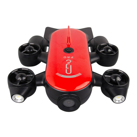
LIQUID ROBOTICS Wave Glider SV3 Setup guide

Customer Training Guide
Pre-Launch Wave Glider® SV3
08033 Rev A i
Customer Training Guide
Pre-Launch
Wave Glider® SV3
Part Number 08033
Revision A
June 2016

Customer Training Guide
Pre-Launch Wave Glider® SV3
08033 Rev A ii
Customer Training Guide
Pre-Launch
Wave Glider® SV3
Copyright © 2016 LRI, Inc.
Legal Notices
Confidential and proprietary information. Valid license or other authorization from LRI, Inc. required for possession, use or copying.
Trademarks
LRI®, LRI, Wave Glider, Wave Glider Management System, WGMS, and SHARC are worldwide trademarks of LRI, Incorporated.
Other products and company names mentioned herein may be the trademarks of their respective owners.
Patents and Inventions
The Wave Glider product is subject to the following patents: Chile (48.628), China (2011 101405179), Egypt (25194), Indonesia
(P0027767), Israel (192828), Japan (2009533257), New Zealand (570562 and 592743), Singapore (144487), South Africa
(200806769), U.S. (7,371,136, 7,641,524, 8,043,133, and 8,287,323). Additional U.S. and non-U.S. patent applications are pending.
All aspects of the Wave Glider product have been developed at private expense by LRI, Inc.
Warranty
The information contained herein is subject to change without notice. The only warranties for LRI, Inc. products and services are
set forth in the express warranty statements accompanying such products and services. Nothing herein should be construed as a
warranty. LRI, Inc. is not liable for technical or editorial errors or omissions contained herein.

Customer Training Guide
Pre-Launch Wave Glider® SV3
08033 Rev A iii
Table of Contents
Chapter 1. Definitions.............................................................................................................. 1
Chapter 2. SV3 Pre-Launch Checklist..................................................................................... 2
Date: Auto filled...................................................................................................................... 2
Tech(s):................................................................................................................................. 2
Payload(s):............................................................................................................................ 2
Ship/Op Area: ....................................................................................................................... 2
Glider Name: Auto filled ........................................................................................................ 2
Organization:........................................................................................................................ 2
Project:.................................................................................................................................. 2
Chapter 3. Software Information............................................................................................. 3
Id: Auto filled.......................................................................................................................... 3
Chapter 4. Communication...................................................................................................... 3
WiFi Connection: Auto filled ................................................................................................. 3
Virtual Relay: Auto filled........................................................................................................ 4
WGMS Iridium: Auto filled..................................................................................................... 4
Vehicle Telemetry received: ................................................................................................ 4
Tracker Telemetry received:................................................................................................ 4
Chapter 5. Configuration......................................................................................................... 5
Topside Radio Direction Finder (RDF) Frequency:............................................................ 5
Hull RDF Frequency:............................................................................................................ 5
Drybox/CCU WGMS name: .................................................................................................. 6
Float name:........................................................................................................................... 6
Glider name: ......................................................................................................................... 6
Thrudder Serial Number: Auto filled..................................................................................... 6
Event definitions: ................................................................................................................. 6
Vehicle and tracker op area defined: .................................................................................. 7
Escalation list created/populated:....................................................................................... 8
Chapter 6. Vehicle Status........................................................................................................ 8
Battery [Wh] > 700 Wh: Auto filled........................................................................................ 8
Solar Power Indicators: > 0.00: Auto filled........................................................................... 9
AMPS Domains: Auto filled..................................................................................................11
Adaptable Modular Power System (AMPS) ...................................................................................... 11

Customer Training Guide
Pre-Launch Wave Glider® SV3
08033 Rev A iv
G1, G2, G3 - General Purpose Expansion Port Connectors ............................................................... 11
D1 - Debug Port Connector ................................................................................................................ 12
Domain_Name=Host, Node=1: Auto filled...........................................................................12
Domain_Name=Thrudder: Auto filled..................................................................................12
Domain_Name=Bat: Auto filled............................................................................................12
Domain Status:....................................................................................................................13
Chapter 7. Float.......................................................................................................................13
Wet-mates connected/lubed:..............................................................................................13
Connector covers secure: ..................................................................................................14
Drybox secure: ....................................................................................................................15
Contact info secure:............................................................................................................15
Hull:......................................................................................................................................16
Skeg/Fin:..............................................................................................................................16
Chapter 8. Sub.........................................................................................................................17
Hardware secure: ................................................................................................................17
Umbilical visual inspection: ...............................................................................................17
Roll pins inserted:...............................................................................................................18
Wings:..................................................................................................................................19
Thrudder: .............................................................................................................................19
Chapter 9. Vehicle Functionality............................................................................................19
Thruster Spin:......................................................................................................................19
Rudder Range of Motion:....................................................................................................20
Rudder right, left, center:....................................................................................................20
Fixed heading test (spin):...................................................................................................22
Waypoint course test (spin): ..............................................................................................22
Octopus Cable 01: Auto filled ..............................................................................................23
Octopus Cable 02: Auto filled ..............................................................................................23
AIS Status: Auto filled...........................................................................................................24
Photo Document:.................................................................................................................24
Chapter 10. Vehicle Communication and Telemetry ............................................................24
WX reporting: Auto filled......................................................................................................24
Airmar GPS: Auto filled ........................................................................................................26
Torpedo GPS: Auto filled......................................................................................................26

Customer Training Guide
Pre-Launch Wave Glider® SV3
08033 Rev A v
Water speed readings: Auto filled........................................................................................26
Obstacle Avoidance Status: Auto filled...............................................................................26
RDF beacon tested w/receiver:...........................................................................................27
Check alarms:......................................................................................................................27
Chapter 11. Comments...........................................................................................................27
Chapter 12. Technician Signature..........................................................................................27
Chapter 13. Save & Submit.....................................................................................................28
Chapter 14. Print.....................................................................................................................28
Upload photos to gallery website with album name YYYY-MM-DD:................................28
Log vehicle modifications in notebook: ............................................................................28
Chapter 15. Post Launch Procedures....................................................................................29
Clear alarms:........................................................................................................................29
Vehicle on mission:.............................................................................................................29
Create LAUNCHED comment in WGMS:............................................................................29

Customer Training Guide
Pre-Launch Wave Glider® SV3
08033 Rev A 1
Chapter 1. Definitions
This checklist is designed to provide trained personnel with a framework for preparing a
wave glider for autonomous operation. Simply filling out this form does not insure that a
wave glider is ready for launch.
The Pre-Launch checklist can be found on the OBSP under: Checklist< SV3 Pre-Launch.
Note: It is recommended that at least two OBSP pages be opened to conduct the Pre-
Launch. Refreshing the OBSP Pre-Launch page will clear any information already
entered, There is no refresh of fields, so values you grab at the time of starting onboard
Pre-Launch are a snapshot. In order to capture all relevant information, be sure that all
payloads, sensors and services are turned on. Finally, when you print a hard copy or pdf
of the pre-launch, the comments section will only show five lines.
AIS: Automatic Identification System
AMPS: Adaptable Modular Power System
APU: Auxiliary Power Unit
CCU: Command and Control Unit
MPU: Modular Payload Unit
OBSP: On-Board Server Page. This is the Wave Glider web page that users can access directly
via WiFi connection or via cellular communication if the user connected to the LRI VPN
(Virtual Private Network) and the wave glider is in cell range. .
PDC: Power Domain Controller
RTF: Radio Tracker Frequency
SN: Serial Number
STP: Standard Temperature and Pressure
Wet-mates: Alternate term for Wave Glider connectors.
WG: Wave Glider
WXS: Weather Station

Customer Training Guide
Pre-Launch Wave Glider® SV3
08033 Rev A 2
Chapter 2. SV3 Pre-Launch Checklist
Date: Auto filled
Date of inspection.
Tech(s):
Name of individual(s) responsible for Pre-Launching the Wave Glider.
Payload(s):
Types of payloads and sensors connected to the system.
Ship/Op Area:
Name of vessel deployed from and where the Wave Glider will be operating (e.g.
Po’okela/Kawaihae).
Glider Name: Auto filled
Name of Wave Glider.
Organization:
Name of WGMS organization that the Wave Glider will be operating in (e.g.
training.wgms.com).
Project:
Name of the current project that the Wave Glider will operate under (e.g. Training).

Customer Training Guide
Pre-Launch Wave Glider® SV3
08033 Rev A 3
Location: Auto filled
Auto filled with the system GPS coordinates.
Chapter 3. Software Information
Id: Auto filled
Auto filled report of wave glider name, Serial Number (SN), Software Version and
Production Build.
Chapter 4. Communication
WiFi Connection: Auto filled
This is to test if the vehicle is broadcasting WiFi. Open Network and Sharing Center –
View available networks and see if desired vehicle is an option.
Logging onto the vehicle webpage:
Click on the WiFi icon and select desired Glider
Password for WiFi connection will be, for example:
1. SV3-010:password = sv3-010-50m
2. Aquaman: password = aquaman-50m
Open a web browser (preferably Google Chrome) andenter 192.168.100.1 in the
address bar to access the vehicle log in page.
1. Username: Individual Specific - Pass: Individual Specific
WGMS –SV3 Commands –VehicleID –Expert –Add User –New user Id (Enter desired user
ID) –Password (Enter desired password) –Virtual Cell/Iridium –Click Add User –Once added
you can now enter ID and Password on login page.
Note: The username and password will be visible in the command log. Insure that this password
is not a common personal password.

Customer Training Guide
Pre-Launch Wave Glider® SV3
08033 Rev A 4
Note: If you do not see a vehicle on WiFi, you can turn it on with SV3 Commands
WiFi ON/OFF = SV3 Commands - Services - wirelessAccesPoint - Com channel
Cell/Iridium - WIFI On - WIFI Off
Virtual Relay: Auto filled
WGMS –Click vehicle icon –Click Raw Outputs –in left hand column check for VR Cell.
WGMS Iridium: Auto filled
WGMS –Click vehicle icon –Click Raw Outputs in left hand column –Iridium will be in
the same section that VR Cell is. It will be labeled IridumStatus under Structure Type.
Under the IMEI section it will be labeled by a combination of numbers.
Note: Iridium will always be on. This way if the Wave Glider goes out of Cell range it will
maintain communication
OBSP - Setup –All Vehicle Parameters –Enable –Look for Iridium Modem –Box
checked = ON
OBSP –Status –Amps –Host Domain –Slot 32 #1 –View if ON or OFF
Note: Always power up the Wave Glider outside (Clear view of sky). When an SV3 is powered
on Iridium is defaulted to ON. This will also allow the default GPS system to boot up properly.
DO NOT SET DEFAULT COMM CHANNEL. THIS WILL CAUSE VERY SERIOUS ISSUES!
Vehicle Telemetry received:
WGMS- First information box when scrolling down (Communications) –If all 0.00 It will
be an alarm. –If there is information double click it to see if it was sent via Cell or
Iridium. This information can also be viewed from the vehicle icon - telemetry tab.
Tracker Telemetry received:
Xeos Resilient Tracker: (White & Black tracker in bow, also known as the Resilient
Tracker) WGMS –Click the drop down menu (searching for gliders and trackers) - By
default; Resilient Trackers will be labeled with a “Res. Tracker”. The numbers are the
last four of the tracker’s IMEI, which can be found printed on the tracker. Information

Customer Training Guide
Pre-Launch Wave Glider® SV3
08033 Rev A 5
within parentheses indicates which vehicle it is on [e.g. Res. Tracker 4510 (SV3-017) or
Res. Tracker 5730 (Quick Silver)]. Etc.
Note: All trackers can have individual names. It is the responsibility of the operator to name the
trackers appropriately.
Battery Power –Click on the “Vehicle” icon – Telemetry - Battery level will be in the
Battery column.
1. It is recommended that the Resilient Tracker battery pack power level is at least
13.4 volts.
2. Battery will be depleted “around” 9.0 volts.
Report Rate can be set on Xeos (online.xeostech.com). Resilient Tracker GPS and
battery status is reported over Iridium at regular pre-configured intervals. The Liquid
Robotics factory configured Resilient Tracker reporting frequency is every 720 minutes
(12 hours), but you can set the reporting rate at 5 minute intervals from 10 minutes up to
1440 minute (24 hour) intervals, depending on your mission requirements.
1. WGMS
2. Click on the “Vehicle” icon – Telemetry –view report rate history to calculate
report rate.
3. It is recommended that youonly use Energizer Industrial (AA) batteries
4. Upon start-up, a tracker reports every 10 minutes for the 1st hour.
5. After the first six reports it will return to its default report rate.
Chapter 5. Configuration
Topside Radio Direction Finder (RDF) Frequency:
Radio beacon that was used in the past to track Wave Gliders with a Yagi antenna at
ranges of 10’s of kilometers in cases where all other communications methods failed.
This equipment has been phased out in most applications.
Hull RDF Frequency:
See Topside RDF Frequency.

Customer Training Guide
Pre-Launch Wave Glider® SV3
08033 Rev A 6
Tracker WGMS name:
See Tracker telemetry received. This should be the name that appears within the Wave
Glider Management System (WGMS).
Drybox/CCU WGMS name:
Name of CCU in WGMS, also the physical label on the CCU.
Float name:
Same as CCU name unless parts/components were transferred between Wave Gliders.
Glider name:
Refers to the Sub, same as CCU name unless parts/components were transferred
between Wave Gliders.
Thrudder Serial Number: Auto filled
OBSP –Status –AMPS –Thrudder Domain –3rd line down –Last 6 digits of S/N
Event definitions:
WGMS –Vehicle icon –Event Definitions in left hand column –View definitions to
ensure they are set up correctly.

Customer Training Guide
Pre-Launch Wave Glider® SV3
08033 Rev A 7
Vehicle and tracker op area defined:
WGMS –Click vehicle icon –Click Operation Polygons –Check to see if the appropriate
Polygon is enabled. Note: 11/11/2015 If two operational polygons (Inclusion) are
enabled the smaller polygon should give one alarm. Once the glider crosses the second
polygon it will send continuous alarms.
There can be multiple Exclusion Zones enabled at one time.
Enabling operational polygons during a prelaunch will cause the wave glider to produce
out of bounds errors. It is recommended to enable the operational polygon before
launching the wave glider. Once the Wave Glider is launched, place it on mission. When
a vehicle is on mission alarms will be sent to individuals that are on the escalation list.
During this process also look at the waypoints that are loaded onto the vehicle. Insure
that all courses are set up and loaded correctly.

Customer Training Guide
Pre-Launch Wave Glider® SV3
08033 Rev A 8
Escalation list created/populated:
Once a vehicle is on mission, the individuals that are on the populated escalation list will receive
alarms created by the Wave Glider.
WGMS –Click vehicle icon –Click Lists in left hand column –Click “New” if there is no
populated list –Name List –Save - Double click Escalation List/Newly created list –If
not on list click New –Type in Item Name (example = John Email) –Click Related Entity
–Click on your name on the list, then click save.
If not on Related Entity list, click New –Fill out information (Email, Name Etc.) –Click
save
Chapter 6. Vehicle Status
Battery [Wh] > 700 Wh: Auto filled
A new and fully charged CCU or APU reports 850-980Wh depending on the version of battery
installed. To read battery status:
(Option 1) OBSP –Status –AMPS –AMPS System Summary –Total battery Power Available

Customer Training Guide
Pre-Launch Wave Glider® SV3
08033 Rev A 9
(Option 2) WGMS –Hover over battery icon (This will be updated every hour)
Note: Minimum battery level for launch depends on weather conditions and Payload type +
quantity of Payloads. Weather conditions consist of sea state, current strength/direction, and the
amount of sunlight in the given area. It is recommended that wave gliders launch fully charged.
Auxiliary Power Units (APU’s) can be added to provide additional battery power when
needed. Each APU provides 850Wh to 980Wh depending on version and age of
batteries. Each APU occupies 1 MPU of space, and plugs into an expansion port. A
maximum of one APU can plug into the backside of another APU, allowing a total of 6
APU’s to be added to the system.
Solar Power Indicators: > 0.00: Auto filled
(Option 1) OBSP –Status –AMPS –Host Domain –Slot 9 #1 –Slot 10 #1 & #2 Note: Slot 9
#2 will always be reading 0.00 and that’s ok.

Customer Training Guide
Pre-Launch Wave Glider® SV3
08033 Rev A 10
(Option 2) WGMS –More Commands –Comment Section –Retrieve Power Status –
Command Reason (Pre-Launch) –Com Channel (VirtualRelayCell) –Send
Vehicle Icon –Vehicle Data Forum –AMPS Solar Input Port Report –(The vehicle will
give a report every hour unless requested). Readings will be in module 1, 3, and 4. Data
will be given in Panel Pwr, Panel Volt, and Panel Cur.
Note: If anything is blocking the solar panels (shadows, tools, etc.) it will cause low reporting.
If testing a fully charged system, the solar panels will also give a low report rate and 1 or more
panels may report zero output. If you cover one of the panels that is reporting, the system will
start reporting a value of zero for the covered panel.

Customer Training Guide
Pre-Launch Wave Glider® SV3
08033 Rev A 11
A good test is to compare the three panels against each other. All three should be giving similar
power status readings. Another test that is recommended is to completely cover/uncover each
panel. Take readings on each panel while covered/uncovered. AMPS may take a few minutes
for values to update.
AMPS Domains: Auto filled
Domains will autofill in the pre-launch checklist if they are turned on and operating correctly.
See example below. At a minimum, the Host (CCU) and the Thrudder domains must be
present. CCU and payload pressures should be between (130 kPa and 105 kPa absolute) at
standard temperature and pressure (STP). Oil filled Thrudder pressure should be between 200
kPa and 170 kPa (absolute) at STP.
Adaptable Modular Power System (AMPS)
The Adaptable Modular Power System (AMPS) enables extremely efficient power management
for a wide range of possible Wave Glider configurations. By generating data on individual power
producers and power consumers in prioritized power domains, AMPS facilitates optimal mission
specific power management. AMPS is defined by a 3-wire power distribution system that
includes hierarchical communications capability for monitoring and control.
AMPS extensibility supports:
1. Scaling the number of power domains.
2. Scaling power generation inputs.
3. Scaling power storage capacity.
G1, G2, G3 - General Purpose Expansion Port Connectors
The G1, G2, and G3 General Purpose Expansion Port connections to the CCU support
AMPS power management logic and also provide Ethernet switching capability for flexible
payload-to-payload and payload-to-CCU communications management. They are designed to
support payloads with multiple sensors or devices that require communications channels with
other payloads and also with the CCU. This is in contrast to the S1, S2, S3, and S4 sensor
supply, with direct communications connections to the CCU.

Customer Training Guide
Pre-Launch Wave Glider® SV3
08033 Rev A 12
D1 - Debug Port Connector
The Debug Port Connector is the primary maintenance port for the CCU. It is identical to a
General Purpose sensor port except that the SPARE1 and SPARE2 lines are dedicated to
providing access to the VMC's serial console port. This connector is also used for an external
battery charger, although an external battery charger can be plugged into any CCU Expansion
Port.
Domain_Name=Host, Node=1:Auto filled
CCU (Command and Control Unit) = (Host) Filled with Nitrogen to 122 kPa Absolute at
STP (WGMS Will give a reading in kPa)
Domain_Name=Thrudder: Auto filled
Thrudder = (Thrudder) Filled with oil and Nitrogen to minimum of 170 kPa-Absolute. 200
kPa-Absolute at STP is the recommended operating pressure (WGMS gives a reading in
kPa-Absolute).
Domain_Name=Bat: Auto filled
Battery Pack = APU, this is a battery pack containing 850Wh-980Wh of additional power
to the system. Battery’s may vary in full charge depending on the age of the battery.
APU’s will plug into G1, G2, or G3 depending on the configuration of the system.
APU’s will have the same pressure and temperature characteristics as CCU’s. Filled with
Nitrogen to 122 kPa - Absolute at STP (WGMS Will give a reading in kPa - Absolute)

Customer Training Guide
Pre-Launch Wave Glider® SV3
08033 Rev A 13
Turning On/Off APU’s:
(Option 1) SV3 Commands –Devices –Either G1, G2, or G3 depending on what it's plugged
into –Power On Expansion Port (ON) –Power Of Expansion Port (OFF)
(Option 2) OBSP –Operate –Power Devices –Turn on G port that the APU is plugged into.
Domain Status:
(Option 1) OBSP –Status –Overall –AMPS Manager.
Note: Expansion port (G1,G2, and G3) payloads are controlled by a PDC board (Power Domain
Controller).
(Option 2) WGMS - SV3 commands –Amps Manager –Domain Statuses –Commands
Log (Bottom of WGMS Home page) –Once Acked, Hover over Combined Acts to view
Pressure and Temperature
Host = CCU
Thrudder = Thrudder
Bat = APU
Payload = Payload/Unknown
Chapter 7. Float
Reference the (Torque Specs for SV3 Fasteners) document for tools needed and torque specs.
Wet-mates connected/lubed:
All connectors were installed with 3M Silicone Lubricant Spray (or appropriate
equivalent, i.e. Dow Corning 4). Inspect for any damage in the system.

Customer Training Guide
Pre-Launch Wave Glider® SV3
08033 Rev A 14
Connector covers secure:
CCU cable Bridges are secured and Thrudder connector covers are installed.

Customer Training Guide
Pre-Launch Wave Glider® SV3
08033 Rev A 15
Drybox secure:
Blue foam is installed. Wiggle test to ensure no movement from CCU/APU/Payloads.
Contact info secure:
Sticker is installed on the cover/name plate with contact information.
Table of contents

