K-Team Khepera III User manual


Documentation Author
F.Lambercy and G.Caprari for K-Team S.A.
Rue Galilee 9
1400 Yverdon-les-bains
Switzerland
email: info@k-team.com
Url: www.k-team.com
Trademark Acknowledgments:
IBM PC: International Business Machine Corp.
Khepera: K-Team and LAMI
Legal Notice:
•The content of this manual is subject to change without notice.
•All effort have been made to ensure the accuracy of the content of
this manual. However, should any error be detected, please inform
K-Team S.A.
•The above notwithstanding K-Team can assume no responsibility for
any error in this manual.
Khepera III manual ver 2.2 1

Table Of Contents
1 Introduction 4
1.1 How to Use this Manual . . . . . . . . . . . . . . . . . . . . . 4
1.2 Safety Precaution . . . . . . . . . . . . . . . . . . . . . . . . . 4
1.3 Recycling . . . . . . . . . . . . . . . . . . . . . . . . . . . . . 5
2 Unpacking and Inspection 6
3 The Robot and Its Accessories 7
3.1 The Khepera III Robot . . . . . . . . . . . . . . . . . . . . . 7
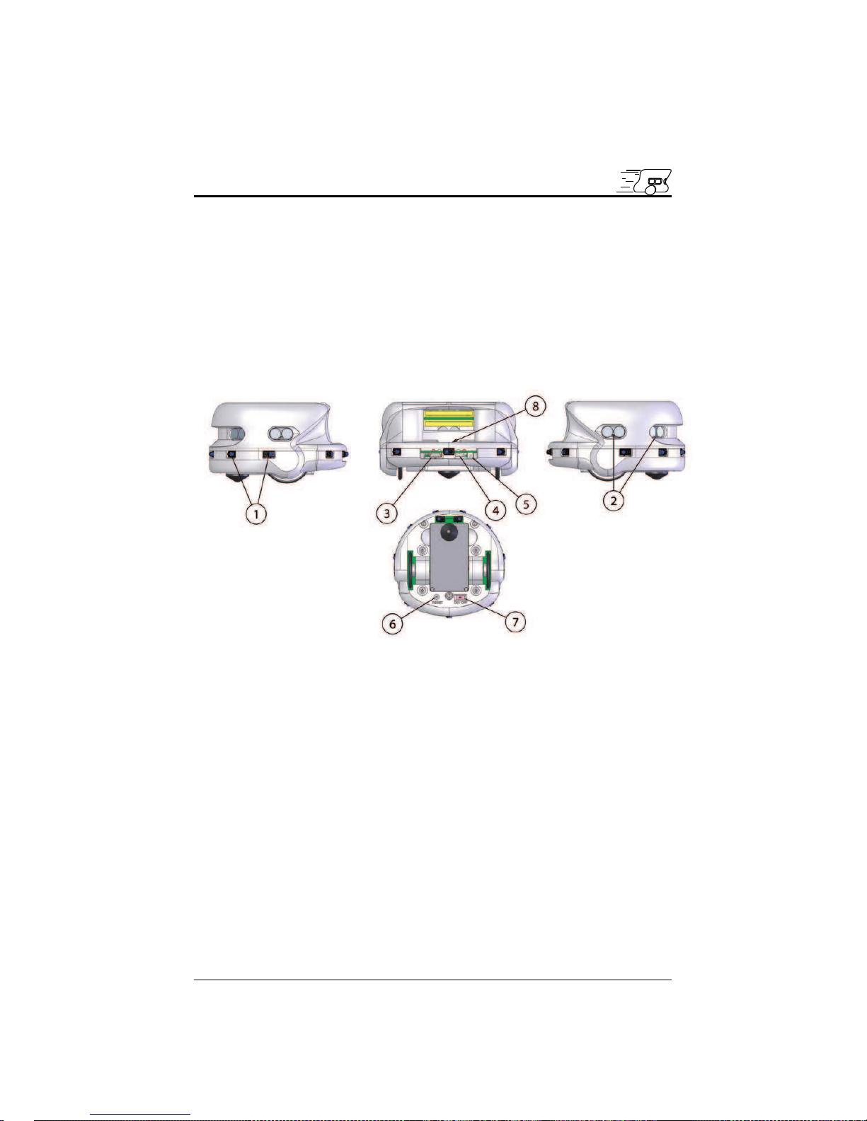
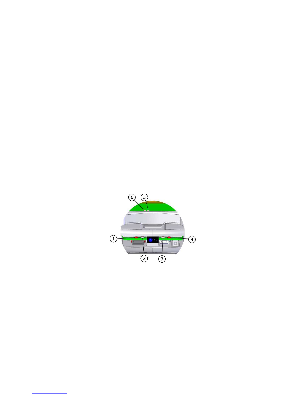
3.1.1 Overview . . . . . . . . . . . . . . . . . . . . . . . . . 7
3.1.2 ON-OFF Battery Switch . . . . . . . . . . . . . . . . . 8
3.1.3 Indication LEDs . . . . . . . . . . . . . . . . . . . . . 8
3.1.4 Serial connector . . . . . . . . . . . . . . . . . . . . . 9
3.1.5 Cable unroller connector . . . . . . . . . . . . . . . . . 10
3.1.6 USB connector . . . . . . . . . . . . . . . . . . . . . . 10
3.1.7 How to plug a KoreBotLE . . . . . . . . . . . . . . . . 11
3.2 Motors and motor control . . . . . . . . . . . . . . . . . . . . 12
3.2.1 Speed . . . . . . . . . . . . . . . . . . . . . . . . . . . 14
3.3 Infra-red Proximity sensors . . . . . . . . . . . . . . . . . . . 16
3.3.1 Ambient light measurements . . . . . . . . . . . . . . 17
3.3.2 Reflected light measurements (proximity) . . . . . . . 17
3.4 Ultrasonic sensors . . . . . . . . . . . . . . . . . . . . . . . . 18
3.5 Battery . . . . . . . . . . . . . . . . . . . . . . . . . . . . . . 19
3.6 Power Supply . . . . . . . . . . . . . . . . . . . . . . . . . . . 19
4 Connections 20
4.1 Configuration for batteries charge . . . . . . . . . . . . . . . . 20
4.2 Configuration for Robot-Computer Communication in standalone 21
4.3 Configuration for Robot-Computer Communication with KoreBotLE 22
4.3.1 Serial link . . . . . . . . . . . . . . . . . . . . . . . . . 22
4.3.2 USB link . . . . . . . . . . . . . . . . . . . . . . . . . 23
4.4 Bluetooth Communication . . . . . . . . . . . . . . . . . . . . 24
4.4.1 Bluetooth communication with KheperaIII . . . . . . 24
4.4.2 Bluetooth communication with KoreBotLE . . . . . . 25
4.4.3 Log On the KoreBotLE with a Bluetooth connection . 25
K-Team S.A. 2

5 Serial Communication Mode 26
5.1 Testing the primary serial link . . . . . . . . . . . . . . . . . 26
5.2 Testing the secondary serial link . . . . . . . . . . . . . . . . 27
5.3 Serial communication protocol . . . . . . . . . . . . . . . . . 28
5.3.1 Testing a simple interaction . . . . . . . . . . . . . . . 28
6 KoreBotLE programming 30
A Communication protocol 33
Khepera III manual ver 2.2 3

1Introduction
1.1 How to Use this Manual
This manual is introducing the Khepera III robot. For a quick start and
overview of the robot’s functions, please read chapter 1 to 4.
Refer to the following summary if a particular information is needed.
If the manual does not cover a particular problem, many more technical
documentation is available online from K-Team website (www.k-team.com)
and especially a Frequently Asked Question document to solve most common
problems and questions.
Unpacking and Inspection: Khepera’s package description.
The robot and its accessories: Khepera Hardware overview and main
functions and accessories description.
Connections: detailed cables connections for various usage.
Serial Communication mode: detailed description for the Serial com-
munication mode between a computer and the robot.
1.2 Safety Precaution
Check the unit’s operating voltage before operation.
It must be identical with that of your local power supply. The operating
voltage is indicated on the nameplate at the rear of the power supply.
All connnections (including extension addition or disconnection) must
be made when the robot and the interface are switched OFF. Otherwise
damages can occur.
Switch OFF the robot if you will not use it for more than a day.
Disconnect the power supply removing it from the wall socket.
Do not manually force any mechanical movement.
Avoid to force, by any mechanical way, the movement of the wheels or
any other part.
If you have any question or problem concerning the robot, please contact
your local Khepera dealer.
K-Team S.A. 4

1.3 Recycling
Think about the end of life of your robot! Parts of the robot can be recycled
and it is important to do so. It is for instance important to keep batteries
out of the solid waste stream. When you throw away a battery, it eventually
ends up in a landfill or municipal incinerator. These batteries, which contain
heavy metals, can contribute to the toxicity levels of landfills or incinerator
ash. By recycling the batteries through recycling programs, you can help to
create a cleaner and safer environment for generations to come. For those
reasons please take care to the recycling of your robot at the end of its life
cycle, for instance sending back the robot to the manufacturer or to your
local dealer.
Thanks for your contribution to a cleaner environment!
Khepera III manual ver 2.2 5

2Unpacking and Inspection
Open the bag and check each item in the box. You should having the
following material.
1. Khepera III robot
2. KoreBotLE ( not included in the Khepera III base package )
3. Power Supply with a primary plug
4. Battery Pack
5. Optional KoreConnect
K-Team S.A. 6

3The Robot and Its Accessories
3.1 The Khepera III Robot
3.1.1 Overview
Figure 3.1: Overview of the Khepera III robot.
Make an external inspection of the robot. Note the location of the fol-
lowing parts:
1. Infrared sensors.
2. Ultrasonic sensors.
3. Main serial connector.
4. USB miniAB connector.
5. Power jack connector.
6. Reset.
7. On / Off.
8. Cable unroller connector.
K-Team S.A. 7

3.1.2 ON-OFF Battery Switch
It allows the user to switch the robot ON or OFF. When ON, the robot is
powered. The robot may even be powered without the battery pack using
the external power supply connector. See figure 3.1 number 7.
3.1.3 Indication LEDs
The Khepera III has six indication LEDs, two for the battery charger, one
for the Power ON, one for the state of the motors controller and two pro-
grammables by the end-user (see figure 3.2).
When the Motor controller state LED is on, one of the two motor con-
troller is in error mode. This could append when a motor is blocked or
a current limit is detected. In this case the controller must be reset by
the dsPIC (’M’ command in serial interface mode or call ’initKH3()’ in a
KoreBotLE program).
For the battery charger, the red one indicates that charge is in progress
and the green one signals when the charge is complete. If there’s no battery
pack when you plug an external power supply, the green one will turn on.
The led 5 and 6 can be set by the user with ’L’ command. See annexe
A Serial communication protocol.
Figure 3.2: LEDs of the Khepera III.
1. Motor Controllers state LED (redD).
2. Power ON LED (green).
3. Charge completed LED (green).
4. Charge in progress LED (red).
5. Programmable LED (green).
6. Programmable LED (red).
Khepera III manual ver 2.2 8

3.1.4 Serial connector
The serial connector contains various serial lines. One serial line which is at
TTL level (0V/+5V) is used to connect a personal computer to the Khepera
III dsPIC (with a KoreConnect). Used only when there is no KoreBotLE
connected. Please see section 4.2.
There is another RS232 (-10V/+10V) used to communicate with the
KoreBotLE, ie to see the KoreBotLE’s boot message. Please see section
4.3.
It is also possible to use the USB link of the KoreConnect to communicate
with the KoreBotLE.
The length of the serial cable should be limited to two meters
for proper operation.
11
9
5
3
17
12. GND
11. GND
7. USB D−
8. USB D+
1. Korebot RXD
2. Korebot TXD
3. dsPIC RXD
4. dsPIC TXD
6. VCC ( +5V )
12
10
8
6
4
2
Figure 3.3: Details of the Khepera III serial connector. Pin 5, 9 & 10 are
not connected.
Khepera III manual ver 2.2 9

3.1.5 Cable unroller connector
The cable unroller connector is a serial and a power connector (see fig-
ure 3.4). You can supply your robot and communicate with the robot
through it. This connector is usefull if you want to supply your robot with
an external power supply (+9V) and keep its mobility with an cable un-
roller. However, if you want to recharge your battery at the same time, it
is mandatory to use the power jack connector.
6. GND
4. GND
5. GND
1. VCC (+9V)
2. dsPIC RXD
3. dsPIC TXD
1
2
35
46
Figure 3.4: Details of the cable unroller connector.
3.1.6 USB connector
The mini-USB connector is usefull only when a KoreBotLE is plugged in the
Khepera III. You can connect directly your PC to the Khepera III with an
ordinary mini-USB cable. To communicate with the KoreBotLE through
the USB connector, please refer to the documentation of the KoreBotLE
(found on the web site www.k-team.com).
Khepera III manual ver 2.2 10

3.1.7 How to plug a KoreBotLE
The Khepera III has been designed to work together with a KoreBotLE,
but as it isn’t mandatory, in the default pack there is no KoreBotLE with
the robot. You can buy it at the same time, in this case, the KoreBotLE
will be mounted into the robot. But if you buy it afterward, you must first
unmount the upper body of the Khepera III, then plug the KoreBotLE on
the extansion connectors (see figure 3.5). If you have any other extansion
(KoreIO, KoreSound, KoreVision, etc...), you must only remove the black
metal plate, and plug your extension on the KoreBotLE.
Figure 3.5: Details of the KoreBotLE assembly.
Khepera III manual ver 2.2 11

3.2 Motors and motor control
Each wheel is moved by a DC motor coupled with the wheel through a 43.2:1
reduction. The motor itself having a 27:1 reduction and the gear box having
a 1.6:1 reduction. The motor has its own embedded incremental encoder,
placed on the motor axis, gives 16 pulses per revolution of the motor. This
allows a resolution of 691.2 per revolution of the wheel that corresponds to
54 pulses per ten millimeter of path of the robot (diameter of the wheel =
41mm, thus each revolution the robot make 128.8mm). By default, the robot
is set in mode encoder resolution x4, in this case for each wheel revolution
the controller motor make 2764 measures. The other encoder configuration
mode is 2x (1382 measures/turn).
Reminder: 1 revolution = 128.8mm = 2764 measures.
Each motor is driven by its own motor controller implemented in a
PIC18F4431. The PIC has direct control on the motor power through a
double H bridge and can read the pulses of the incremental encoder.
The motor control block acts as slave devices on the I2C bus. When the
KoreBotLE is not connected to the Khepera III robot, the main robot CPU
will turns itself into an i2c master. When the KoreBotLE is connectedm, it
becomes the i2c master.
Each motor controller switches its motor ON and OFF at a given fre-
quency and during a given time. By this way, the motor react to the time
average of the power supply, which can be modified by changing the period
the motor is switched ON. This means that only the ratio between ON and
OFF periods is modified, as illustrated in figure 3.6. This power control
method is called ”pulse width modulation” (PWM). The PWM value is
defined as the time the motor is switched ON.
Khepera III manual ver 2.2 12

time
power
OFF
ON
basic period
50µs
ON period
time
power
OFF
ON
basic period
95%
ON period
time
power
OFF
ON
basic period
5%
ON period
Figure 3.6: The “Pulse Width Modulation”(PWM) motor supply mode is
based on a ratio between the ON time and the total time. The basic switch-
ing frequency is constant.
Each motor controller can perform the control of the speed or the position
of the motor, setting the correct PWM value according to the real speed or
position read on the incremental encoders.
Both DC motors can be controlled by a PID controller. Every term of
this controller(Proportional, Integral, Derivative) is associated to a constant,
setting the weight of the corresponding term: Kp for the proportional, Ki
for the integral, Kd for the derivative.
The motor controller can be used in two control modes: the speed or
position mode. The active control mode is set according to the kind of
command received. If the controller receives a speed control command, it
switches to the speed mode. If the controller receives a position control
command, the control mode is automatically switched to the position mode.
Different control parameters (Kp, Ki and Kd) can be set for each of the two
control modes.
Khepera III manual ver 2.2 13

3.2.1 Speed
Used in speed mode, the controller has as input a speed value of the wheels,
and controls the motor to keep this wheel speed.
The speed value is a division of a constant value by the time between
encoder pulsations. In default mode (encoder resolution x4 and postscaler
1:4), a measure is made four times every pulse. Then each revolution of the
wheel, 2764 measures are made. The constant value is defined by the maxi-
mum time multiplied by 256 (0xFFFF * 256 = 16’776’960). This operation
allows a better PID calculation for the lower speed.
MotorSpeed =16′776′960
T imer5value
To convert into a real time, use the following calculation (this time is
the delay between two measures):
T ime =
T imer5value
P ostscaler
fosc /4
T mr5P rescaler
Where fosc = 20MHz and Tmr5Prescaler = 8 (default).
To get the real speed in mm/s:
RealSpeed =W heelCircumf erence
T ime ∗2764
Where WheelCircumference is 128.8mm and 2764 correspond to the number
of measures per revolution of the wheel.
Here’s an example with MotorSpeed = 20’000, Tmr5Prescaler = 8, Postscaler
= 4 and encoder resolution = x4
T imer5value =16′776′960
20′000 = 839
T ime =
839
4
20′000′000/4
8
= 0.336[ms]
RealSpeed =128.8
0.000336 ∗2764 = 138.9[mm/s]
RealSpeed =MotorSpeed
Kspeed [mm/s]
Where Kspeed is 144.01 when default configuration is used.
The maximum reachable speed is 48’000 (= 333 mm/s) in open loop,
and 43’000 (= 298 mm/s) in regulation mode. And the minimum is 2’000
(= 13.9 mm/s) with regulation control.
Khepera III manual ver 2.2 14

Used in position profile mode (’F’ command), the controller has as in-
put a target position of the wheel, an acceleration and a maximal speed.
Using this values, the controller accelerates the wheel until the maximal
speed is reached, and decelerates in order to reach the target position. This
movement follows a trapezoidal speed profile, as described in figure 3.7.
time
time
position speed
acc -acc
start position
target position
max_speed
Figure 3.7: Speed profile to reach a target position with a fixed acceleration
(acc) and maximal speed (max speed).
The input values and the control mode of this controller can be changed
at every moment. The controller will update and execute the new profile
in the position mode, or control the wheel speed following the new value in
the speed mode.
First configure the speed profile (’J’ command) with the needed param-
eters. Then you can perform a move with the position profile mode (’F’
command). See annexe A for more details about communication protocole.
Khepera III manual ver 2.2 15

3.3 Infra-red Proximity sensors
Khepera III hase nine sensors placed around the robot and two placed on
the bottom. The latters allow experiments like line following. They are
positioned and numbered as shown in figure 3.9.
Figure 3.8: Bottom view of the IR sensors
These sensors embed an infra-red light emitter and a receiver. For de-
tailed description, please refer to the manufacturer’s datasheet. The eight
sensors are TCRT5000, reflective optical sensors from Vishay Telefunken.
Khepera III manual ver 2.2 16

This sensor device allows two measures:
- The normal ambient light. This measure is made using only the re-
ceiver part of the device, without emitting light with the emitter. A
new measurement is made every 33 ms. During the 33 ms, the eleven
sensors are read in a sequential way every 3 ms. The value returned
at a given time is the result of the last measurement made.
- The light reflected by obstacles (= proximity). This measure is made
emitting light using the emitter part of the device. The returned
value is the difference between the measurement made emitting light
and the light measured without light emission (ambient light). A new
measurement is made every 33 ms. During the 33 ms, the eleven
sensors are read in a sequential way every 3 ms. The value returned
at a given time is the result of the last measurement made.
The output of each measurement is an analog value converted to a 12
bit digital value . The following two sections illustrate the meaning of this
12 bit values.
3.3.1 Ambient light measurements
Ambient light measurement is strongly influenced by the robot’s environ-
ment. Depending on the light source type, color, and distance, ambient
light measurement profile might vary. It is not recommended to use
light source with large emission in the infrared range, as this could
confuse the IR sensors.
3.3.2 Reflected light measurements (proximity)
Sensors are mainly meant to detect obstacles around the Khepera. Mea-
surements for reflected light depends on objects reflectivity and on ambient
light conditions. Objects color, materials and surfaces do have an influence
on the sensors response. Moreover, as any sensor, IR sensors are subject
to environmental noise. For all these reasons, graphics below are given for
information only and should not be considered as references.
Khepera III manual ver 2.2 17

Figure 3.9: Relative collector current vs distance
3.4 Ultrasonic sensors
In its base set, 5 sensors are placed around the robot and are positioned and
numbered as shown in figure 3.10.
5 sensors are in fact 5 pairs of ultrasonic devices where each pair is
composed of one transmitter and one receiver.
The ultrasonic sensor are powered by a 20 Vdc source. The nominal
frequency of these transducers is 40kHz +/- 1kHz.
Parameters such as max number of echo, timeout and active sensors are
parametrizable through a configuration api (See ’C’ command in chapter A).
By default, you have maximum 3 echos, sensor 3 (front) is active, timeout
is set to see from 20cm to 4 meters.
The last parameter is if the upper body is mounted or not (default
mounted). When the upper body is mounted, there’s some noise because
of inside rebound echo, which are deleted in software. In fact, you could
improve the detection of the nearest obstacles (20cm to 40cm) removing the
upper body.
Each measure return the number of founded echos, the distance in cm
of each echo, the amplitude of each, and the time (time stamp) when the
echo was seen.
The value returned by the command, is the white noise measured before
than a Ultrasonic pulse was sent. Then the real amplitude of each echo will
be its amplitude minus the white noise. See command ’G’ in chapter A for
more details about the ultrasonic command.
For more details about the ultrasonic sensor, please check at Midas com-
ponent, the transceiver is 400ST100 and the receiver is a 400SR100.
Khepera III manual ver 2.2 18
Table of contents
Other K-Team Robotics manuals