2
User Manual
Table of Contents
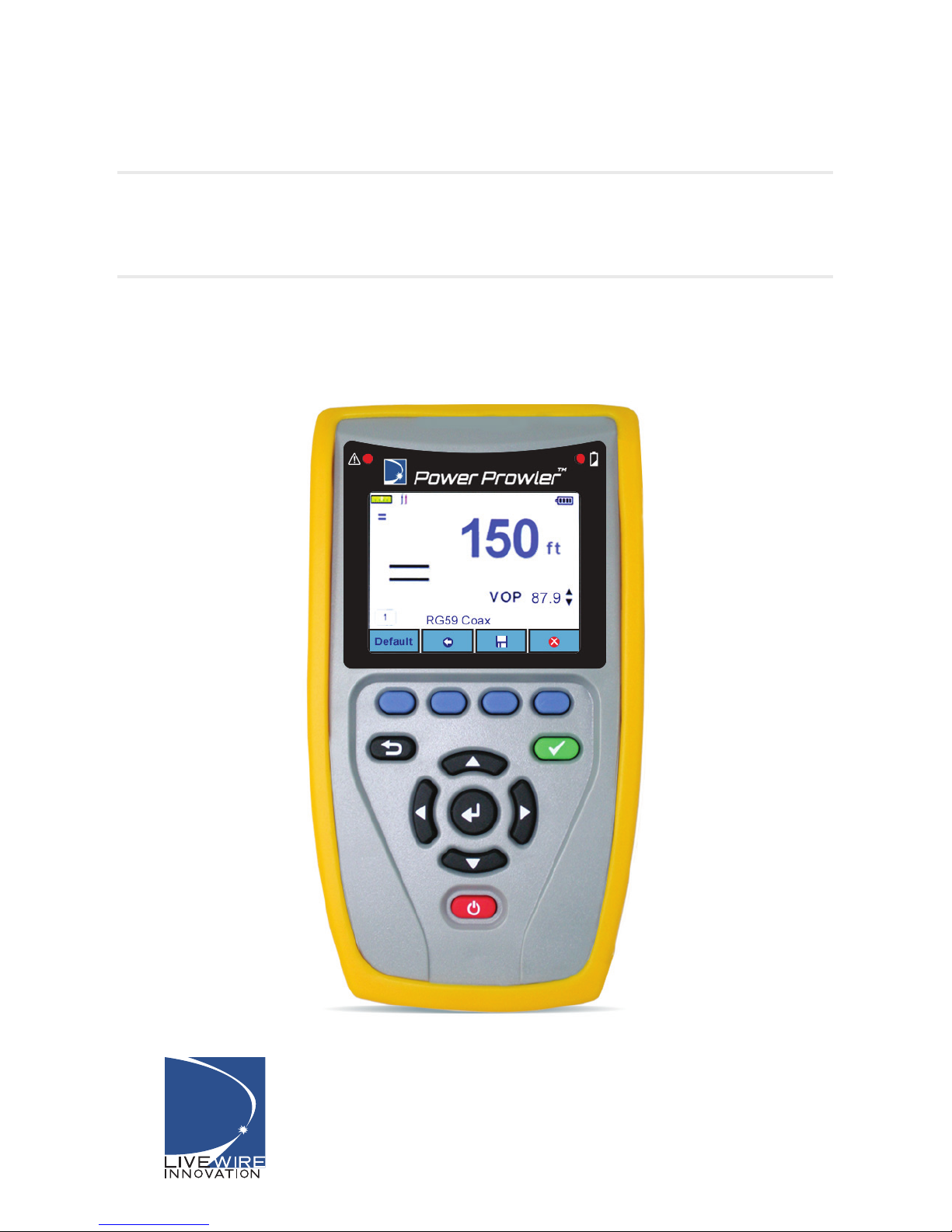
3-In-1 DMM/TDR Cable Fault Finder for
Energized and Unenergized Cables
About the Power Prowler............................................................................3
Features and Functions...........................................................................3
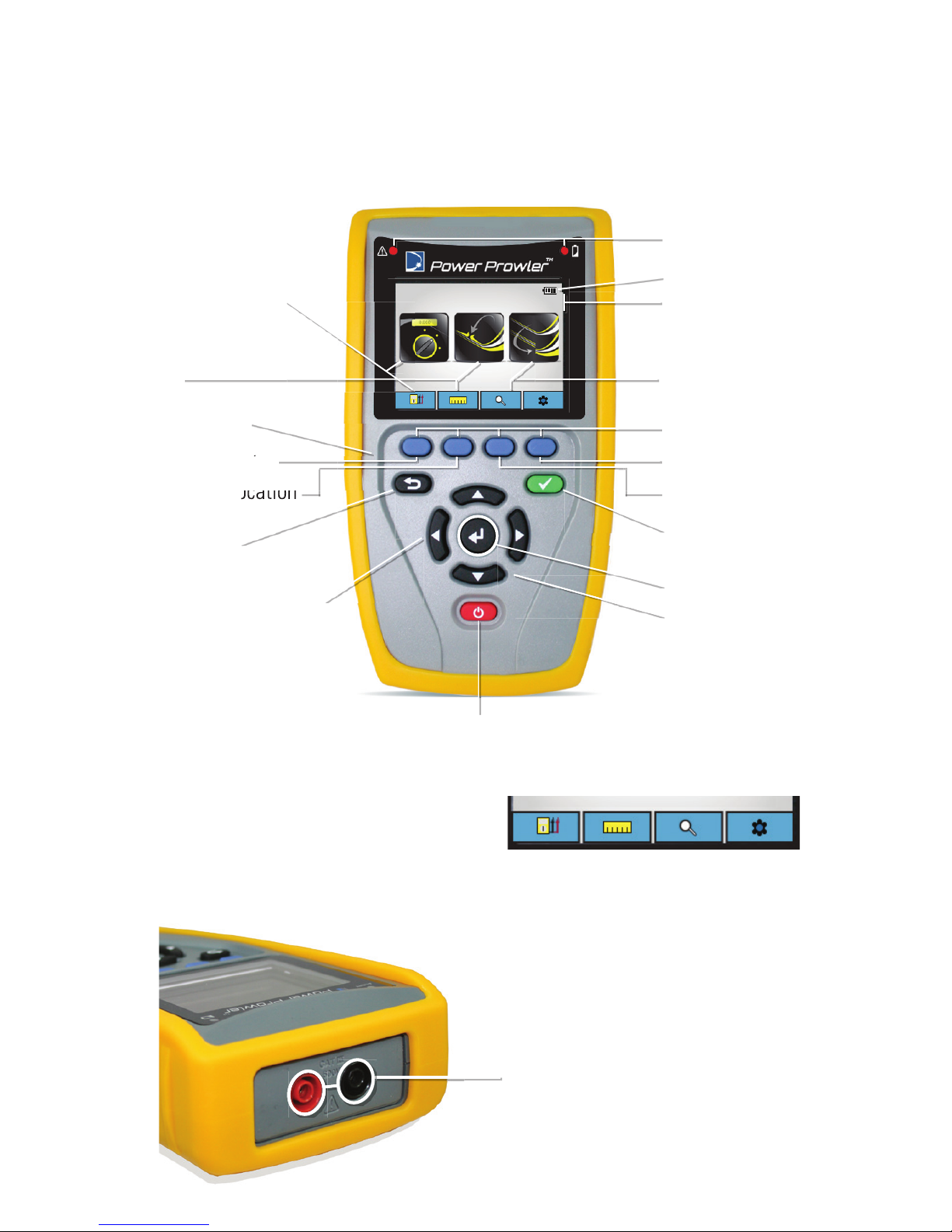
Physical Features.....................................................................................3
Optional Accessories...............................................................................4
Safety Information...................................................................................5
Power Prowler Description......................................................................6
Terms and Descriptions...........................................................................7
Types of Faults..........................................................................................7
General Operations..................................................................................8
On/Off.....................................................................................8
Automatic Power Down...........................................................................8
System Settings..........................................................................................9
Digital Multimeter Options (DMM)...........................................................11
Fault Location (TDR Operation)................................................................14
To Begin Test for Fault Location.............................................................14
Fault Location Display............................................................................15
Functions........................................................................................15
Changing VOP Values............................................................................16
Calibrating VOP Values..........................................................................16
Favorites......................................................................................18
Conducting a Test...................................................................................19
Live Event Detection.................................................................................20
Run a Live Event Detection Test..............................................................20
Maintenance.............................................................................................21
Batteries...........................................................................................21
Cleaning..............................................................................................21
Storage........................................................................................21
Customer Service......................................................................................22
Specications......................................................................................23
Patents/Intellectual Property....................................................................25
Warranty Information...............................................................................26
Registration........................................................................................26
Disposal........................................................................................26
Returns........................................................................................26
Power ProwlerTM