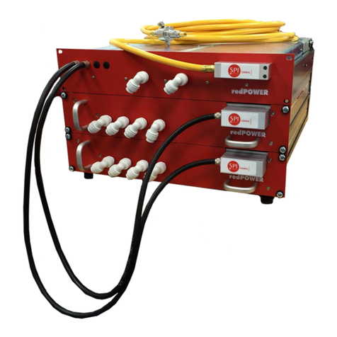
SPI Lasers redPOWER QUBE User manual

redPOWER QUBE
Cased Fiber Laser
Instructions for Use

© 2016 SPI Lasers UK Ltd.
Commercial in Confidence
SM-S00500 Revision A 21 October 2016
redPOWER QUBE Cased Fiber Laser User Manual
2
Safety Notes
These safety notes indicate potential hazards associated with this QUBE Fiber Laser and the
probable consequences of not avoiding them. Directions on the safe use of this QUBE Fiber
Laser are provided in the remainder of these Instructions for Use, particularly Sections 3
Health and Safety, 7 Installation, and 8 Operating Instructions.
Throughout these Instructions for Use warning messages are given in contexts in which a
hazard may occur.
General Hazard Information
WARNING: Ensure that all Users are fully aware of all safety
implications identified in these Instructions for Use before
attempting to install, operate or maintain this QUBE Fiber Laser.
WARNING: Attempts to modify or alter this QUBE Fiber Laser or
the use of controls or adjustments or performance of procedures
other than those specified in these Instructions for Use may render
this QUBE Fiber Laser unsafe.
Attempts to modify or alter this QUBE Fiber Laser or the use of controls or adjustments or
performance of procedures other than those specified in these Instructions for Use additionally
will invalidate the warranty and may result in patent infringement.
Laser Integrators are not authorized to modify this QUBE Fiber Laser.

© 2016 SPI Lasers UK Ltd.
Commercial in Confidence
SM-S00500 Revision A 21 October 2016
redPOWER QUBE Cased Fiber Laser User Manual
3
Laser Hazard Information
WARNING: The output aperture of this QUBE Fiber Laser may
emit both invisible and visible laser radiation.
The invisible laser radiation may be in excess of the Accessible
Emission Limit (AEL) for a Class 4 laser. The invisible radiation can
be up to approximately 1.5kW CW in normal operation and 2.3kW
with a single fault. The wavelength of this invisible radiation is in the
range 1050-1250nm.
Additionally, this QUBE Fiber Laser contains embedded lasers that
emit invisible laser radiation up to approximately 3.2kW CW in
normal operation and 4.8kW CW with a single fault. The
wavelength of this invisible radiation is in the range 900-1000nm.
AVOID EYE OR SKIN EXPOSURE TO DIRECT OR SCATTERED
RADIATION.
Contact with direct or scattered laser radiation can cause damage
to the eyes, burn human tissue and start fires.
The optical connector shall be mounted in a protective housing
which prevents human access to laser radiation (including errant
radiation) in excess of the AEL for class 1, for example a housing
meeting the requirements of EN 60825-4.
WARNING: The output aperture of this QUBE Fiber Laser may
emit both invisible and visible laser radiation.
The visible laser radiation is below the Accessible Emission Limit
(AEL) for a Class 2 laser. The wavelength of the visible laser
radiation is in the range 630 –680nm.
DO NOT STARE INTO BEAM.
WARNING: Before carrying out any maintenance task detailed in
these Instructions for Use ensure that power to the QUBE Fiber
Laser is disconnected. Failure to do so may lead to serious
personal injury.
Electrical Hazard Information
WARNING: This QUBE Fiber Laser contains hazardous AC
voltages up to 240V. These may still be present even when the
power is disconnected.
Contact may cause electrical shock and injury

© 2016 SPI Lasers UK Ltd.
Commercial in Confidence
SM-S00500 Revision A 21 October 2016
redPOWER QUBE Cased Fiber Laser User Manual
4
CAUTION: This QUBE Fiber Laser is designed to BS EN 60204-
1:2006+A1:2009 and must be grounded for safety and to comply
with regional electrical codes.
Failure to do so may result in electric shock and incorrect operation
of the QUBE Fiber Laser.
CAUTION: There is no Mains power isolation switch on this QUBE
Fiber Laser. The QUBE Fiber Laser should only be connected to a
switched electricity supply which can be isolated.
Weight Hazard Information
CAUTION: This QUBE Fiber Laser is heavy and so precautions
must be taken when lifting and moving.
Failure to do so may cause serious injury
Pressure Hazard Information
CAUTION: Ensure an approved overpressure safety device
compliant with ISO4126-1 (or equivalent) is installed when
connecting this QUBE Fiber Laser to an external chiller or factory
water supply.
Failure to do so may result in water leaks and damage to the QUBE
Fiber Laser and auxiliary equipment.
Laser for Incorporation
CAUTION: This PRISM Fiber Laser is specifically designed to be a
laser for incorporation or integration into other equipment. As such,
it is not required to, and does not, meet the requirements for a
stand-alone laser system as defined by IEC/EN 60825-1.

© 2016 SPI Lasers UK Ltd.
Commercial in Confidence
SM-S00500 Revision A 21 October 2016
redPOWER QUBE Cased Fiber Laser User Manual
5
CONTENTS
1Structure and Scope of these Instructions for Use 11
2Definition of Symbols and Terms 12
3Health and Safety 13
3.1 General 13
3.2 Intended Use of the QUBE Fiber Laser 14
3.3 Hazards 14
3.4 Compliance 16
3.5 Labelling 18
4Document References 20
5redPOWER QUBE Product Tour 20
5.1 Key Parts 21
5.2 Key Features 23
5.3 Software Tools 27
5.4 Control System Safety Functions 28
5.5 Auxiliary Equipment 30
5.6 Explanation of Order Codes 31
6Getting Started 32
6.1 Receiving and Inspection 32
6.2 Unpacking and Handling 32
6.3 Unpacking the Beam Delivery Optic 34
7Installation 35
7.1 Safety and Compliance During Installation 35
7.2 Location and Environment 35
7.3 Mounting 36
7.4 Cooling Water Connections 36
7.5 FiberView Installation 39
7.6 Electrical Connections 40
7.7 Routing the Beam Delivery Optic 63
7.8 Connecting and Disconnecting the PIPA-Q Optical Connector 64
8Operating Instructions 68
8.1 Before Operation 68
8.2 Powering the QUBE Fiber Laser On and Off 69
8.3 Control of Operating Temperature 69
8.4 Alarms and Warnings 70
9Laser Control and FiberView 71
9.1 Overview 71
9.2 Basic Operation 71
9.3 Parameter Sets 74

© 2016 SPI Lasers UK Ltd.
Commercial in Confidence
SM-S00500 Revision A 21 October 2016
redPOWER QUBE Cased Fiber Laser User Manual
6
9.4 Process Cycles 78
9.5 Other Settings 80
10 Basic Control using Serial Communication 82
10.1 Overview 82
10.2 Functionality 83
10.3 Basic Serial Communication Protocol Message References 85
11 Machine Interface Reference 85
11.1 Overview 85
11.2 Default Input Functionality 86
11.3 Default Output Functionality 107
11.4 Machine Interface Protocol Message References 112
12 Alarm and Warning Messages 113
12.1 Alarm Code Definitions 113
12.2 Warning Code Definitions 115
13 Maintenance 118
13.1 Periodic Inspection 118
13.2 General Cleaning 118
13.3 Cleaning Optics 119
14 Disposal 119
15 General Information 119
15.1 Trade Marks 119
15.2 Licensing 119
15.3 Software 119
15.4 Warranties 120
15.5 Copyright 120
15.6 Changes 120
16 Contact Information 121
17 General Specifications 121
17.1 Operating Conditions 122
17.2 Non-Operating Conditions 123
17.3 Utility Requirements 124
18 Optical Specifications 126
18.1 General Optical Specifications 126
18.2 Optical Output –PIPA-Q Optical Connector 127
19 Mechanical Specifications 128
19.1 Overall Dimensions and Masses 128
19.2 PIPA-Q Optical Connector 130
20 Customer Service 131

© 2016 SPI Lasers UK Ltd.
Commercial in Confidence
SM-S00500 Revision A 21 October 2016
redPOWER QUBE Cased Fiber Laser User Manual
7
FIGURES
Figure 1 WEEE Symbol........................................................................................................................... 16
Figure 2 redPOWER QUBE Cased Fiber Laser Key Parts .................................................................. 21
Figure 3 redPOWER QUBE Cased Fiber Laser Key Parts .................................................................. 22
Figure 4 QUBE Cased Fiber Laser Key Features................................................................................... 23
Figure 5 redPOWER PRISM FL Module Key Features........................................................................ 24
Figure 6 PIPA-Q Optical Connector with Protection Against Back-Reflection........................................ 26
Figure 7 redPOWER QUBE Cased Fiber Laser with Auxiliary Equipment........................................... 30
Figure 8 QUBE Fiber Laser in Packing Case as Received..................................................................... 33
Figure 11 Bubble Wrap and Top Foam Block Removed......................................................................... 33
Figure 12 Four Point Sling Attached ....................................................................................................... 34
Figure 13 QUBE Fiber Laser on Trolley.................................................................................................. 34
Figure 15 Cooling Water Connections to QUBE Fiber Laser.................................................................. 37
Figure 16 Interface connectors................................................................................................................ 41
Figure 17 Internal Connections for Electrical Supply .............................................................................. 43
Figure 18 Machine Interface Connections Circuits.................................................................................. 46
Figure 19 PL5 Programmable Inputs ...................................................................................................... 47
Figure 20 PL5 Programmable Outputs.................................................................................................... 48
Figure 21 Connections to PL81............................................................................................................... 54
Figure 22 Typical connections to PL82 (control contact and indicator lamps)........................................ 56
Figure 23 Typical connections to PL82 (PLC)......................................................................................... 57
Figure 24 Timing diagram........................................................................................................................ 58
Figure 25 Typical Connections to PL91 .................................................................................................. 59
Figure 26 A Typical Connection to PL96................................................................................................. 60
Figure 27 A Typical Connection to PL98................................................................................................. 61
Figure 29 PIPA-Q with protective cap ..................................................................................................... 65
Figure 30 Connector before removal of protective tape.......................................................................... 66
Figure 31 Red Dots Aligned .................................................................................................................... 66
Figure 32 Connector Inserted into Receiver............................................................................................ 67
Figure 33 Fiber Laser Connection Dialog................................................................................................ 72
Figure 34 FiberView Overview Screen.................................................................................................... 73
Figure 35 FiberView Parameter Editor.................................................................................................... 76

© 2016 SPI Lasers UK Ltd.
Commercial in Confidence
SM-S00500 Revision A 21 October 2016
redPOWER QUBE Cased Fiber Laser User Manual
8
Figure 36 Shape Editor Window.............................................................................................................. 78
Figure 37 Steps Grouped Into Process Cycles ....................................................................................... 79
Figure 38 FiberView Process Cycle Editor.............................................................................................. 79
Figure 39 Solenoid Set Point Update Screen.......................................................................................... 81
Figure 40 State Transition Diagram ........................................................................................................ 83
Figure 41 Moving to STANDBY in Remote Control................................................................................. 88
Figure 42 Moving to OFF in Remote Control .......................................................................................... 88
Figure 43 Entering Remote Control (OFF state, Laser Start Set)........................................................... 89
Figure 44 Entering Remote Control (STANDBY or ON state, Laser Start Clear) ................................... 89
Figure 45 Entering Remote Control (STANDBY or ON state, Laser Start Set) ...................................... 89
Figure 46 Moving to ON in Remote Control............................................................................................ 92
Figure 47 Moving to STANDBY in Remote Control (No ramp down time configured)............................ 92
Figure 48 Moving to STANDBY in Remote Control (Ramp down time configured)................................ 93
Figure 49 Moving to ON state in Remote Control before the state has moved to the STANDBY state . 93
Figure 50 Entering Remote Control (STANDBY state, Laser ON Input Set) .......................................... 94
Figure 51 Entering Remote Control (ON state, Laser ON Input Set)...................................................... 94
Figure 52 Entering Remote Control (ON state, Laser ON Input Clear, No ramp down time configured)95
Figure 53 Entering Remote Control (ON state, Laser ON Input Clear, Ramp down time configured).... 95
Figure 54 Starting a Process Cycle in Remote Control........................................................................... 96
Figure 55 Stopping a Process Cycle in Remote Control (No ramp down time configured in active step
Parameter Step) ...................................................................................................................................... 96
Figure 56 Stopping a Process Cycle in Remote Control (Ramp down time configured in active Step
Parameter Step) ...................................................................................................................................... 97
Figure 57 Starting a Process Cycle in Remote Control before the state has moved to the STANDBY
state......................................................................................................................................................... 97
Figure 58 Entering Remote Control (STANDBY state, Process Cycle Start Input SET) ........................ 98
Figure 59 Entering Remote Control (Process Cycle Active, Process Cycle Start Input Set, No ramp
down time configured in active step Parameter Step)............................................................................. 98
Figure 60 Entering Remote Control (Process Cycle Active, Process Cycle Start Input Set, Ramp down
time configured in active step Parameter Step) ...................................................................................... 99
Figure 61 Entering Remote Control (STANDBY state, Process Cycle Start Input Set).......................... 99
Figure 62 Entering Remote Control (Process Cycle Active, Process Cycle Start Input CLEAR, No ramp
down time configured in active step Parameter Step)........................................................................... 100
Figure 63 Entering Remote Control (Process Cycle Active, Process Cycle Start Input CLEAR, Ramp
down time configured in active step Parameter Step)........................................................................... 100
Figure 64 Advancing Process Cycle Steps in Remote Control............................................................. 102

© 2016 SPI Lasers UK Ltd.
Commercial in Confidence
SM-S00500 Revision A 21 October 2016
redPOWER QUBE Cased Fiber Laser User Manual
9
Figure 65 Advancing Process Cycle Steps in Remote Control(Before Process Cycle Wait Is Set) ..... 103
Figure 66 Alarm Reset........................................................................................................................... 104
Figure 67 Alarm Reset When in the ON state....................................................................................... 105
Figure 68 Edge Trigger Operation(Pulsed Output Only)....................................................................... 106
Figure 69 Gated Trigger Operation (Pulsed Output)............................................................................. 107
Figure 70 Gated Trigger Operation (CW Output).................................................................................. 107
Figure 71 Environmental Conditions for Non-Condensing Operation................................................... 123
Figure 72 Overall Dimensions............................................................................................................... 129
Figure 74 Outline Drawing –PIPA-Q Beam Delivery Optic .................................................................. 131
TABLES
Table 1 Safety, Explanatory and Compliance Labels ............................................................................. 18
Table 2 Information Labels...................................................................................................................... 19
Table 3 Explanation of Order Code......................................................................................................... 31
Table 4 Water Tubing.............................................................................................................................. 38
Table 5 Water Tubing.............................................................................................................................. 38
Table 6 Laser Integrator Supplied PC –For Operating FiberView.......................................................... 39
Table 7 Interface Connectors.................................................................................................................. 41
Table 8 Electrical Supply Cord Wire Sizes.............................................................................................. 42
Table 9 Serial Port Connections.............................................................................................................. 43
Table 10 PL5 Machine Interface Pin Out ................................................................................................ 45
Table 11 Laser Inputs.............................................................................................................................. 49
Table 12 Laser Status Outputs................................................................................................................ 51
Table 14 Parameter Set Attributes.......................................................................................................... 74
Table 15 Process Cycle Step Attributes.................................................................................................. 80
Table 16 Default Configuration of Machine Interface Inputs................................................................... 86
Table 17 Default Configuration of Machine Interface Outputs ................................................................ 86
Table 18 Replacement Windows........................................................................................................... 119
Table 19 Contact Information................................................................................................................ 121
Table 20 Environmental Operating Conditions...................................................................................... 122
Table 21 Non-Operating Conditions...................................................................................................... 123
Table 22 Electrical Requirements ......................................................................................................... 124

© 2016 SPI Lasers UK Ltd.
Commercial in Confidence
SM-S00500 Revision A 21 October 2016
redPOWER QUBE Cased Fiber Laser User Manual
10
Table 23 Power Consumption............................................................................................................... 124
Table 24 Cooling Water Requirements ................................................................................................. 125
Table 25 Cooling Requirements (Connection to Manifold) ................................................................... 125
Table 23 Required Chiller Capacity....................................................................................................... 126
Table 26 Cooling Requirements (Connection to PIPA-Q Optical Connector)....................................... 126
Table 27 General Optical Specifications ............................................................................................... 126
Table 28 Single Mode Optical Specifications........................................................................................ 127
Table 29 50µm Multimode Optical Specifications ................................................................................. 127
Table 30 100µm Multimode Optical Specifications ............................................................................... 128
Table 31 Case Lengths ......................................................................................................................... 128
Table 32 Mechanical Specifications –PIPA-Q Optical Connector........................................................ 130

© 2016 SPI Lasers UK Ltd.
Commercial in Confidence
SM-S00500 Revision A 21 October 2016
redPOWER QUBE Cased Fiber Laser User Manual
11
1 Structure and Scope of Instructions for Use
These Instructions for Use for SPI Lasers’ redPOWER®QUBE Cased Fiber Laser contains
all the information that Users needs to know for its safe and efficient use. This information is
important. These Instructions for Use should be read before installing and using the QUBE
Fiber Laser and made available for reference at the location where the QUBE Fiber Laser is
being used. Additional or replacement copies are available from SPI Lasers.
These Instructions for Use are divided into the sections below which provide Users with health
and safety information before introducing the QUBE Fiber Laser and then guiding them
through its installation, operation, maintenance and disposal. Lastly it provides other useful
information and the QUBE Fiber Laser’s specifications.
1
Structure and Scope of Instructions for Use
2
Definition of Symbols and Terms
3
Health and Safety
4
Document References
5
redPOWER QUBE Product Tour
6
Getting Started
7
Installation
8
Operating Instructions
9
Laser Control and FiberView
10
Basic Control using Serial Communication
11
Machine Interface Reference
12
Alarm and Warning Messages
13
Maintenance
14
Disposal
15
General Information
16
Contact Information
17
General Specifications
18
Optical Specifications
19
Mechanical Specifications
20
Customer Service
The QUBE Cased Fiber Lasers covered by these Instructions for Use have order codes:
SP
-
0300
0500
0750
1000
1500
-
C
-
W
-
020
050
100
-
10
15
20
-
PIQ
-
0
B
12
-
001
-
001
The order code can be found on a label on the rear panel of the QUBE Fiber Laser.
Details of the options shown in bold are expanded in Section 5.6 below.

© 2016 SPI Lasers UK Ltd.
Commercial in Confidence
SM-S00500 Revision A 21 October 2016
redPOWER QUBE Cased Fiber Laser User Manual
12
2 Definition of Symbols and Terms
This symbol alerts the user to the hazard of exposure to laser
radiation
This symbol alerts the user to the hazard of exposure to electricity
This symbol alerts the user to the hazard caused by the weight of
this QUBE Fiber Laser
This general warning symbol emphasizes important information
needed during installation and operation
This symbol identifies the protective conductor terminal (ground
point)
WARNING:
Indicates a hazard with a medium level of risk which, if not avoided,
could result in death or serious injury
Warnings must be observed to prevent personal injury to yourself
and others.
CAUTION:
Indicates a hazard with a low level of risk which, if not avoided,
could result in minor or moderate injury
Cautions must be observed to prevent personal injury and damage
to or destruction of equipment or loss of operational effectiveness.

© 2016 SPI Lasers UK Ltd.
Commercial in Confidence
SM-S00500 Revision A 21 October 2016
redPOWER QUBE Cased Fiber Laser User Manual
13
QUBE Fiber
Laser:
QUBE Fiber Laser as used herein means the item that was
procured from SPI Lasers.
This QUBE Fiber Laser is a complete fiber laser system. By
‘complete’ it is meant a laser system as sold and ready for use for
its intended purpose without modifications to the specification of
the product.
This QUBE Fiber Laser is specifically designed to be a laser for
incorporation or integration into other equipment. As such, it does
not meet the full requirements for a stand-alone laser system as
defined by 21 CFR 1040.10 and IEC/EN 60825-1.
This QUBE Fiber Laser is not a consumer product and is not to be
sold on or made available as such.
Laser
Integrator:
Any person, company or organisation who integrates this QUBE
Fiber Laser into equipment, or any person, company or
organisation who uses this QUBE Fiber Laser in the form as
supplied by SPI Lasers.
A Laser Integrator is skilled in and understands the integration
issues surrounding the use, design and supply of laser products to
end users in the end markets which it supplies.
User:
Individuals or organizations that use this QUBE Fiber Laser. User
includes the Laser Integrator and the end user
Authorised
Personnel:
Those who have attended official Training Courses and have been
certified as competent.
SPI Lasers:
SPI Lasers UK Ltd.
3 Health and Safety
3.1 General
This section gives information on the hazards which may be encountered during installation,
operation and maintenance of this QUBE Fiber Laser and steps to reduce the risk. Also
included is information on laser and electrical safety compliance. All safety instructions,
including those in the Safety Notes and those in other sections of these Instructions for Use,
must be followed. Not following safety instructions may constitute a hazard to Users and third
parties or cause damage to property and the QUBE Fiber Laser.
Only Authorised Personnel who have been instructed in, and fully understand, the necessary
safety procedures should operate this QUBE Fiber Laser. Access must be restricted to
Authorised Personnel.
Any local safety requirements for the operation of this equipment must be complied with.

© 2016 SPI Lasers UK Ltd.
Commercial in Confidence
SM-S00500 Revision A 21 October 2016
redPOWER QUBE Cased Fiber Laser User Manual
14
Throughout the documentation, ‘WARNING’, and ‘CAUTION’ paragraphs appear. It is the
responsibility and duty of all Users who operate and maintain this equipment to fully
understand the WARNING and CAUTION and act in order to reduce or eliminate hazards.
3.2 Intended Use of the QUBE Fiber Laser
This QUBE Fiber Laser has been designed exclusively for incorporation or integration into
other equipment for processing:
solid metals, including metal alloys and metal powders
ceramics in both solid and powder form
plastics
composite materials
Operating the device within the limits of its designated use requires the user to:
observe the instructions set out in this operating manual
install and use this QUBE Fiber Laser in compliance with international, national and
local regulations regarding laser safety, for example IEC/EN 60825-1 and 21 CFR
1040.10.
install and use this QUBE Fiber Laser in compliance with international, national and
local regulations regarding the safety of electrical equipment, for example BS EN
60204
wire and connect the electrical lines to this QUBE Fiber Laser in compliance with
international, national and local regulations regarding electromagnetic compatibility
(EMC), for example the relevant sections of IEC/EN 61000 and FCC CFR47
not move this QUBE Fiber Laser when it is switched on (except that the optical
connector may be moved provided that the bending limits of the conduit are observed)
carry out necessary inspection and maintenance work
This QUBE Fiber Laser is not intended:
for processing in connection with flammable or explosive materials
for use in an explosion prone environment
SPI Lasers cannot be held liable for any damage resulting from such use. The risk lies entirely
with the User.
3.3 Hazards
3.3.1 Laser Hazards
All Warnings, including those in the Safety Notes and those in other sections of these
Instructions for Use, must be heeded.

© 2016 SPI Lasers UK Ltd.
Commercial in Confidence
SM-S00500 Revision A 21 October 2016
redPOWER QUBE Cased Fiber Laser User Manual
15
Laser emissions from the housing of the QUBE Fiber Laser and the conduit of the beam
delivery optic are less than the AEL for Class 1 of IEC/EN 60825-1 with a single fault.
WARNING: Care should be taken especially when controlling this
QUBE Fiber Laser remotely across a network.
Failure to do so could result in another User being exposed to
hazardous levels of radiation.
It is the responsibility of the Laser Integrator to ensure that when
controlled remotely no hazardous levels of radiation are emitted
when unsafe to do so.
3.3.2 Electrical Hazard
CAUTION: This QUBE Fiber Laser is designed to BS EN 60204-
1:2006+A1:2009 and must be grounded for safety and to comply
with regional electrical codes.
Failure to do so may result in electric shock and incorrect operation
of the QUBE Fiber Laser.
This QUBE Fiber Laser is not provided with any electrical supply cord (flex or lead).
Only qualified technical personnel who are familiar with the equipment should remove the
covers from the laser. No electrical hazard exists if the system is operated normally.
3.3.3 Thermal Hazard
In normal operation the QUBE Fiber Laser should not get hot. However if a fault occurs the
external surfaces may get hot.
3.3.4 Materials Processing Hazards
Materials processing can generate vapour, fumes, solid particulates and other air
contaminants that may irritate, be toxic, or even fatal. It is the responsibility of the user to
ensure that all relevant safety precautions are followed and that any legal requirements are
adhered to in accordance with local legislation. It is advised that Material Safety Data Sheets
(MSDS) for any material to be processed are evaluated and that adequate measures for fume
extraction and venting are considered. Interaction of the beam with certain materials can
cause potentially harmful levels of visible radiation to be emitted. Appropriate protective
measures must be taken.
CAUTION: It is essential that any debris associated with laser
processing is removed and cleaned away on a regular basis.
Failure to do so may result in fire.

© 2016 SPI Lasers UK Ltd.
Commercial in Confidence
SM-S00500 Revision A 21 October 2016
redPOWER QUBE Cased Fiber Laser User Manual
16
3.3.5 Other Hazards
While most of the hazard comes from laser radiation, there are certain non-beam hazards that
are often associated with use of laser systems. The QUBE Fiber Laser requires mains power
and is water-cooled. Electricity and water, individually or in combination, may create hazards.
It is recommended that the QUBE Fiber Laser should be installed sufficiently far above the
floor to reduce the risk from electricity in the case of flooding: at least 250mm is
recommended.
Mechanical hazards may include moving parts in cutting, welding and material handling
systems.
High temperatures and fire hazards may also result from the operation of Class 4 lasers.
3.4 Compliance
Within the EU, the QUBE Fiber Laser is CE marked and is supplied with a Declaration of
Conformity. The standards which SPI Lasers declares that the QUBE Fiber Laser is in
conformity with, and the directives which SPI Lasers declares that the QUBE Fiber Laser
complies with the requirements of are listed in the Declaration of Conformity.
Within the USA, the QUBE Fiber Laser is shipped with an appropriately completed FDA 2877
form.
It is the responsibility of the Laser Integrator to ensure that the integrated laser system
conforms with the appropriate standards and complies with the appropriate directives.
Nonetheless, many of the electronic and labelling requirements have been incorporated into
the QUBE Fiber Laser to facilitate compliance.
3.4.1 Europe: WEEE Directive
Figure 1 WEEE Symbol
This symbol indicates that, at end of life, this QUBE Fiber Laser should be separately
collected from unsorted waste.
3.4.2 Europe: RoHS Directive
This QUBE Fiber Laser is in conformity with European RoHS Directive. Compliance is
demonstrated through conformance with this standard which is harmonised to the RoHS
directive:
BS EN 50581:2012

© 2016 SPI Lasers UK Ltd.
Commercial in Confidence
SM-S00500 Revision A 21 October 2016
redPOWER QUBE Cased Fiber Laser User Manual
17
3.4.3 Europe: Machinery Directive
This QUBE Fiber Laser does not fall within the meaning of ‘machinery’ given in the Machinery
Directive, 2006/42/EC, and therefore SPI Lasers cannot declare conformity with the Directive.
However SPI Lasers recognises that Laser Integrators may require the integrated laser
system to comply with the Directive. SPI Lasers has therefore designed for compliance to
parts of the standards listed below which are harmonised to the Machinery Directive:
EN11252:2013
EN13849-1:2015
EN13849-2:2012
EN11554:2008
EN12100:2010
EN12198-1:2000+A1:2008, EN12198-2:2002+A1:2008, EN12198-3:2002+A1:2008
EN 60204-1:2006+A1:2009
3.4.4 Europe: Low Voltage Directive
This QUBE Fiber Laser falls within the scope of the Low Voltage Directive as the Directive
applies to electrical equipment designed for use with a voltage rating of greater than 75V. SPI
Lasers has therefore demonstrated compliance to parts of the standards given below which
are harmonised to the Low Voltage Directive:
EN 60204-1:2006+A1:2009
IEC/EN 60825-1
This QUBE Fiber Laser is specifically designed to be a laser for incorporation or
integration into other equipment. As such, it is not required to, and does not, meet the
requirements for a stand-alone laser system as defined by IEC/EN 60825-1.
During installation it is vital that the laser hazard is fully managed. In particular, the Laser
Integrator is required to provision the engineering requirements detailed in IEC/EN
60825-1. These include, but are not limited to:
Provision of an additional protective housing which prevents human access or
exposure to laser radiation in excess of the AEL for Class 1 laser systems from the
output aperture. (IEC/EN 60825-1 section 4.2).
Provision of a remote interlock connector which when open-circuit prevents access
to laser radiation in excess of Class 1M (IEC/EN 60825-1 section 4.4).
Provision of a fail-safe or redundant audible or visible emission indicator at the
laser aperture if it is located more than 2m from the original emission indicator
(IEC/EN 60825-1 section 4.7).
Note that the visible alignment laser carries a Class 2 laser rating as defined by IEC/EN
60825-1.

© 2016 SPI Lasers UK Ltd.
Commercial in Confidence
SM-S00500 Revision A 21 October 2016
redPOWER QUBE Cased Fiber Laser User Manual
18
3.4.5 Europe: EMC Directive
This QUBE Fiber Laser falls outside the scope of the EMC Directive as it is intended
exclusively for an industrial assembly operation for incorporation into other apparatus.
However SPI Lasers recognises that Laser Integrators may require the integrated laser
system to comply with the directive. SPI Lasers has therefore designed for compliance to
parts of the standards listed below which are harmonised to the EMC Directive:
BS EN 55011:2009+A1:2010.
3.4.6 USA: CFR Title 21 Part 1040, Food And Drug Administration
This QUBE Fiber Laser falls outside the scope of 21 CFR part 1040 as 21 CFR part 1040
does not apply to laser products which are sold to a manufacturer for use as components.
However SPI Lasers recognises that Laser Integrators may require the integrated laser
system to comply with the regulation. SPI Lasers has therefore demonstrated compliance to
parts of the European standard:
IEC/EN 60825-1
Under Laser Notice 50, CDRH will not object to conformance with many sections of IEC
60825-1, as amended, as alternatives to comparable sections of 21 CFR §1040.10.
3.4.7 USA: CFR Title 47, Federal Communications Commission
This QUBE Fiber Laser is designed for compliance with:
FCC CFR47: §15.107 Conducted emission limits
FCC CFR47: §15.109 Radiated emission limits.
3.5 Labelling
Labels are placed on the top and rear panels of the QUBE Fiber Laser to warn of potential
hazards and to provide other useful information.
Table 1 to Table 2 below show the labels and give their locations.
Table 1 Safety, Explanatory and Compliance Labels
Rating plate label (Information may vary) (rear panel)

© 2016 SPI Lasers UK Ltd.
Commercial in Confidence
SM-S00500 Revision A 21 October 2016
redPOWER QUBE Cased Fiber Laser User Manual
19
Laser label (Information may vary) (rear panel)
Cautions label (top panel)
Laser hazard (optical connector)
Table 2 Information Labels
QUBE Fiber Laser identification (rear panel)
Address, Patents, WEEE and CE labels (rear panel)

© 2016 SPI Lasers UK Ltd.
Commercial in Confidence
SM-S00500 Revision A 21 October 2016
redPOWER QUBE Cased Fiber Laser User Manual
20
Water Flow and Return Labels (rear panel)
4 Document References
Document number
Description
FS-S00138
QUBE Cased Fiber Laser Installation Drawing
SM-S00482
QUBE Fiber Laser Serial Interface Manual
SM-S00499
redPOWER Fiber Laser Serial Communications Protocol
SM-G00047
Introduction to the Laser Cutting Process
These documents may be downloaded by going to 'Customer Login' at the top right of SPI
Lasers’ home page: www.spilasers.com.
5redPOWER QUBE Product Tour
The range of redPOWER QUBE Cased Fiber Lasers builds on many years of experience of
SPI Lasers in designing, developing and supplying fiber lasers into a wide range of industrial
laser processing applications. It gives laser integrators the capability to manufacture industrial
laser machines with maximum output power levels from 300W up to many kilowatts. QUBE
Fiber Lasers can be operated in continuous wave (CW) or modulated (CWM) modes for
applications enabled by fiber lasers and applications traditionally served by lamp pumped and
diode pumped solid-state lasers. A flexible control architecture has been implemented using a
combination of analogue, digital and logic user interfaces.
The optical power is generated by a PRISM Fiber Laser (FL) Module using SPI Lasers’
proprietary1GTWave®active fiber technology and reliable pump diodes to produce a high
power, high brightness output. The output from the PRISM Fiber Laser Module is guided to
the Laser Integrator’s optics by a single mode (SM) or multimode (MM) delivery fiber supplied
with an industry standard PIPA-Q optical connector. A ruggedized conduit including SPI
Lasers’ Fiber Continuity Monitoring System (FCMS) protects the delivery fiber.
1US 6,826,335, US 7,221,822, US 7,660,034, US 8,270,070, US 8,743,454 and granted patents in
other territories
Other manuals for redPOWER QUBE
1
Table of contents
Other SPI Lasers Measuring Instrument manuals
Popular Measuring Instrument manuals by other brands

Mastech
Mastech MS2138/R Operation manual

Ludlum Measurements
Ludlum Measurements Frisker 3276 Series manual
YSI
YSI EcoSense DO200A Operation manual
Dwyer Instruments
Dwyer Instruments UTG Installation and operating instructions
KROHNE
KROHNE WATERFLUX 3070 Handbook
KRAL
KRAL OME Series operating instructions
