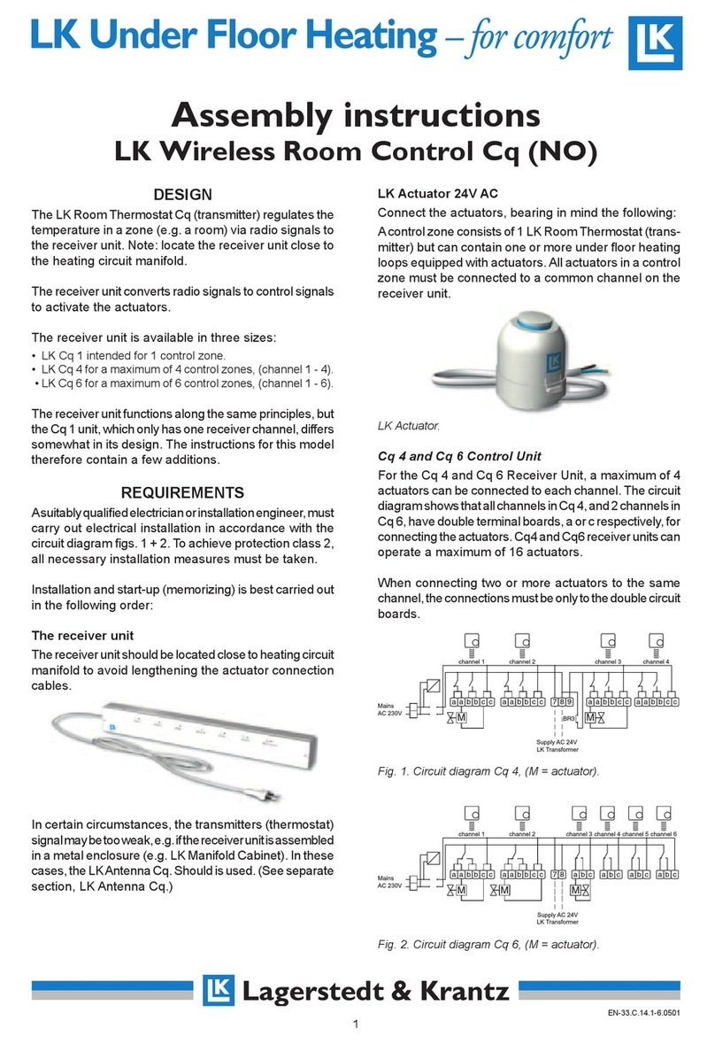
LK ICS.2 User manual

LK ICS.2 Quick Guides - Installation & Reset
Installation Svenska
Reset Svenska
Installation English
Reset English

2
33.C.159.1409
Quick Guides | ICS.2
Back to start
Check the antenna connections.
Connect the receiver unit to the
power grid.
Connect the actuators to the lower row of connectors in the receiver unit. The
connectors for the actuators are marked .
Up to three actuators can be connected to one connector.
If wired thermostats are to be used in the system, these should be connected
to the upper row in the receiver unit. The connectors for the thermostats are
marked .
A maximum of one thermostat per thermostat connector.
Installation of ICS.2 Systems
Connecting actuators and wired thermostats
1.1
Termostater / Thermostats
Ställdon / Actutators
1
M
UL
A
1
12
374568
32 87654
230VAC
FUSE
BOILERPUMP
2
M
1
M
BUS
SETBACK
Pwr
3
M
4
M
5
M
6
M7
M8
M
NO
T
NC
SET
V
V
1
1.2 1.3

3
33.C.159.1409
Quick Guides | ICS.2
Back to start
The Master unit is setup by pressing and holding the L and A buttons until the
lights of the receiver unit lights up to a solid green light. This shows that the unit
is set as Master.
In a system containing several receiver units, one of these is to be assigned as
being the Master unit.
Del 2 - Setup of the Master unit
Note: This part of the setup procedure should be performed in all systems.
2.1

4
33.C.159.1409
Quick Guides | ICS.2
Back to start
Confirm the setup of the Master unit by pressing the L button once. This
switches all the lights of the unit off.
The unit is preferably marked as Master in the lid of the receiver unit
.
2.2

5
33.C.159.1409
Quick Guides | ICS.2
Back to start
Put the Master unit in learning mode by holdning the L-button until the light
turns a solid green.
3.1
Del 3 - Setup of Slave units
Note: This part of the setup is only needed in systems with more than one receiver unit.

6
33.C.159.1409
Quick Guides | ICS.2
Back to start
Hold the L button on one of the receiver units that are to be set as Slaves
until the L light turns orange. The light for the channel which is assigned to the
receiver unit turns on to a green light. Slave units are assigned a number ranging
from 2 to 8.
The receiver unit is preferably marked as a Slave and its assigned number in the
lid of the receiver unit.
3.2

7
33.C.159.1409
Quick Guides | ICS.2
Back to start
Push the L button on the Slave unit to confirm the setup. This turns all the lights
of the unit off.
Repeat these steps for each additional receiver unit in the system.
3.3

8
33.C.159.1409
Quick Guides | ICS.2
Back to start
When all Slave units are setup, the procedure is finalized by pressing the L button
on the Master unit once. All the lights on the Master unit will be switched off.
3.4

9
33.C.159.1409
Quick Guides | ICS.2
Back to start
Prepare the themostats of the system.
For wireless thermostats:
Remove the plastic insulation from the battery compartment (marked in the red
circle). The room thermostat display will show RUR.
Wired room thermostat:
Check that the room thermostat is connected to
the receiver. The room thermostat display will
show RUW.
Note: The installation of the room thermostats is the same whether it is a
wireless or wired connection to the receiver.
Del 4 - Setup of room thermostats
4.1

10
33.C.159.1409
Quick Guides | ICS.2
Back to start
Put the receiver unit that is to be controlled by the room thermostat in learning mode
by pressing the L button until the L light turns green.
4.2

11
33.C.159.1409
Quick Guides | ICS.2
Back to start
On the thermostat, hold SET until the display shows MATE.
4.3

12
33.C.159.1409
Quick Guides | ICS.2
Back to start
The lights of the receiver unit turns on to a orange light for the L light and a solid
green for the channel lights. Choose the channel or channels by pressing the
corresponding channel buttons (1 – 8). To show that a channel has been chosen
the light for that channel starts to blink.
Press the channel button again to undo a choice of channel.
Already occupied channels are shown by an orange light.
4.4

13
33.C.159.1409
Quick Guides | ICS.2
Back to start
When the channels for the thermostat has
been chosen this is confirmed by pressing the
SET button of the thermostat. The display will
then show SYNC while synchronizing with the
receiver unit (this might take a while).
If this process takes an unreasonable long time
the synchronizing can be restarted by pressing
SET once more.
When the synchronizing process is done
the display will show the standard mode
showing temperature and other miscellaneous
information. This confirms that the setup is
completed for this thermostat.
Repeat the steps for each thermostat that is to
be connected to this receiver unit.
4.5

14
33.C.159.1409
Quick Guides | ICS.2
Back to start
When all the thermostats are setup the process is completed by pressing the L
button on the receiver unit once.
Repeat Part 4 of this Quick Guide for every receiver unit in the system.
The installation of ICS.2 is completed when all the thermostats are setup
together with their respective receiver unit,
4.6

15
33.C.159.1409
Quick Guides | ICS.2
Back to start
Confirm by pressing the SET button once.
If a termostat for some reason no longer is communicating with its receiver unit,
the termostat needs to be reset and setup once more.
To begin resetting a termostat, hold both the left and right arrow buttons until
the display shows DEFA.
Resetting of ICS.2 Systems
Resetting Thermostats
1.1
1.2

16
33.C.159.1409
Quick Guides | ICS.2
Back to start
When the reset is completed the termostat will return to its factory default
mode.
Wireless thermostats will display RUR
Wired thermostats will display RUW
If the termostat can’t communicate with its receiver unit during the reset, the
display will show WAIT during a longer period. If this happens push both the left
and right arrow button once more to confirm the reset.
1.3
1.4

17
33.C.159.1409
Quick Guides | ICS.2
Back to start
To reset a receiver unit, hold both the A and 8-buttons (A and 1 for RF 1 units)
for about 10 seconds until all the channel lights flashes red for a brief moment.
This erases all connections to all the termostats paired to this receiver unit as
well as all other receiver units. These connections needs to be setup again for the
system to function as intended.
Remove one of the batteries for about 15 seconds to make sure the reset is
completely carried out. Mind the polarity of the batteries and make sure that it
remains the same when the battery is put back in.
1.5
2.1
Resetting Receiver Units

18
33.C.159.1409
Quick Guides | ICS.2
Back to start
NOTE: If you reset the Master receiver unit in a system, all the Slave receivers
needs to be reset as well.
Disconnect the power to the receiver unit for about 30 seconds to make sure
the reset is fully completed.
2.2
2.3
Master Receiver Unit Slave Receiver Unit(s)

19
33.C.159.1409
Quick Guides | ICS.2
Tillbaka till start
Koppla in nätsladden till
mottagarenheten.
Kontrollera att antennen är ansluten.
Anslut ställdonen i den nedre av de två plintraderna märkta .
Upp till tre ställdon kan kopplas till varje ställdonsutgång.
Om systemet innehåller trådförbundna termostater ska dessa anslutas i den övre
plintraden märkta .
Max en rumstermostat per termostatingång.
Installation av ICS.2 System
Inkoppling av Ställdon och trådförbundna termostater
1.1
Termostater / Thermostats
Ställdon / Actutators
1
M
UL
A
1
12
374568
32 87654
230VAC
FUSE
BOILERPUMP
2
M
1
M
BUS
SETBACK
Pwr
3
M
4
M
5
M
6
M7
M8
M
NO
T
NC
SET
V
V
1
1.2 1.3

20
33.C.159.1409
Quick Guides | ICS.2
Tillbaka till start
Ställ in Master-enheten genom att hålla inne L och A knapparna tills lamporna
för L och samtliga kanaler tänds till ett grönt sken. Detta visar att denna enhet är
inställd som Master.
I system med flera mottagarenheter utses en av dessa till Master-enhet.
2.1
Del 2 - Inlärning av Masterenhet
Notera: Denna del ska utföras i alla installationer oavsett antal mottagarenheter.
Table of contents
Languages:
Other LK Thermostat manuals
Popular Thermostat manuals by other brands

Honeywell
Honeywell Q682B installation instructions

Robertshaw
Robertshaw 7700 user manual

Neomitis
Neomitis RTANEOA Installation and operating instructions

Vive Comfort
Vive Comfort TP-N-721 installation manual

Specified Controls
Specified Controls SC-T32-TS installation manual

Salus
Salus DT300 quick start guide