LMS BBQ09G03 User manual

LTR50001050, Rev. E
12/22/14

WARNING
If the information in this manual is not followed
exactly, a re or explosion may result causing
property damage, personal injury or loss of
life.
Do not store or use gasoline or other ammable
vapors and liquids in the vicinity of this or any
other appliance.
Do not store an LP cylinder not connected for
use in the vicinity of this or any other appliance.
A re resulting in serious injury or death may
occur.
If you are installing a natural gas grill, you are
responsible for ensuring that the natural gas
line installed is safe to use. LMS will not be held
responsible for an improperly installed gas line.
Safety Instructions
Placement and Location ................1
Set-Up ..............................1
Operation............................1
Maintenance and Repair ................2
Storage..............................2
Precautions Regarding Children ..............2
Proper Location of the Grill
Ensuring Proper Ventilation .............3
Construction materials .................4
Built-in Construction
Built-in Dimensions....................5
Enclosure Ventilation ..................7
Gas and Electrical Supply Requirements
Gas Requirements .....................8
Electrical Supply Requirements .........10
Installation and Connection
Connecting the Grill and Side Burner.....11
Leak Testing Procedure................14
Using Your Grill
Basic Grill Operation ..................15
Grill Controls ........................16
Lighting the Burners ..................16
Gas Cylinder Orientation...............18
Optional Grill Accessories
Sear Zone Infrared Burner .............19
Pizza Brick Tray ......................19
Smoke Tray .........................19
Charcoal Tray........................20
Griddle Tray .........................21
Pull-Out Cutting Board ................21
Cleaning and Maintenance
Stainless Steel Care and Cleaning .......22
Cleaning the Interior of Your Grill .......23
Covering Your Grill ...................24
Seasonal Cleaning ....................25
Appendix
Troubleshooting .....................27
Converting from LP to NG..............29
Replacement Parts ...................32
Installing Sear Zone Burners ...........34
Limited Warranty.....................35
Read all instructions before you
operate your grill.
Save these instructions!
Copyright 2014 LMS. All rights reserved. Duplication without
written consent is strictly prohibited. Cal Flame™ is registered
trademark.
Due to continuous improvement programs, all models,
operation, and/or specications are subject to change
without prior notice.
LTR50001050, Rev. E
12/22/14
250-464
CONTACT INFORMATION
For customer service, please contact your authorized
dealer immediately. If you need additional information
and/or assistance, please contact:
LMS Customer Service Department
1462 East Ninth Street
Pomona, CA 91766.
Toll Free: 1-800-225-7727
Fax: 1-909-629-3890
California Proposition 65 Warning: Chemicals known to
the State of California to cause cancer, birth defects or
other reproductive harm are found in and/or created
by the combustion of natural gas, propane, butane and
other fuels. Always operate this unit as described in the
owner’s manual and in well ventilated areas.

G Series Gas Grills
LTR50001050, Rev. E
Safety Instructions
www. c a l a m e b b q . c o m
1
C• al Flame™ grills are designed for outdoor
use only.
Never locate this appliance in an enclosed room, • under a sealed overhead structure, or in any
type of enclosed area such as a garage, shed, or
breezeway. Keep clear of trees and shrubs.
Do not place this grill under or near windows or •
vents that can be opened into your home.
Cal Flame™ grills are not intended for installation •
in or on recreational vehicles or boats.
Maintain sufcient distance as to not overheat any •
overhead combustible material such as a patio
cover.
The area surrounding your new grill should be •
kept clean and free from ammable liquids and
other combustible materials such as mops, rags or
brooms, as well as solvents, cleaning uids, and
gasoline.
Do not use the grill, grill cabinet, or area surrounding •
the grill as a storage area for ammable or plastic
items. Do not store the liquid propane (LP) cylinder
in the vicinity of this or any other appliance when
it is not being used.
the grill and is visible when the hood is lowered or
on the right side of the chassis. There is an area
on the back cover of this manual where you can
write down this information.
We recommend that a licensed contractor install •
your Cal Flame™ grill. Installation must conform
to local codes, or in the absence of local codes,
with either the National Fuel Gas Code, ANSI
Z223.1 / NFPA54, Natural Gas and Propane
Installation Code, CSA B149.1, or Propane
Storage and Handling Code, B149.2), as
applicable.
To prevent re and smoke damage, remove all •
packaging material before operating grill.
Before you start cooking, clean the entire grill •
thoroughly with hot, soapy water. This is necessary
to remove residual solvents, oil and grease used
in the manufacturing process. The grates should
also be thoroughly cleaned in the same manner.
WARNING: Improper installation, adjustment, alteration, service or maintenance
can cause injury or property damage. Read the installation, operating and maintenance
instructions thoroughly before installing or servicing this equipment.
DANGER
What To Do If You Smell Gas
Shut off gas to the appliance.•
Extinguish any open ame.•
Open lid.•
If odor continues, keep away from the •
appliance and immediately call your
gas supplier or your re department.
Safety Instructions
Placement and Location
Set-Up
Operation
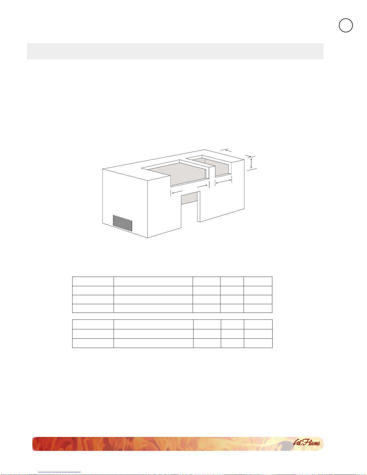
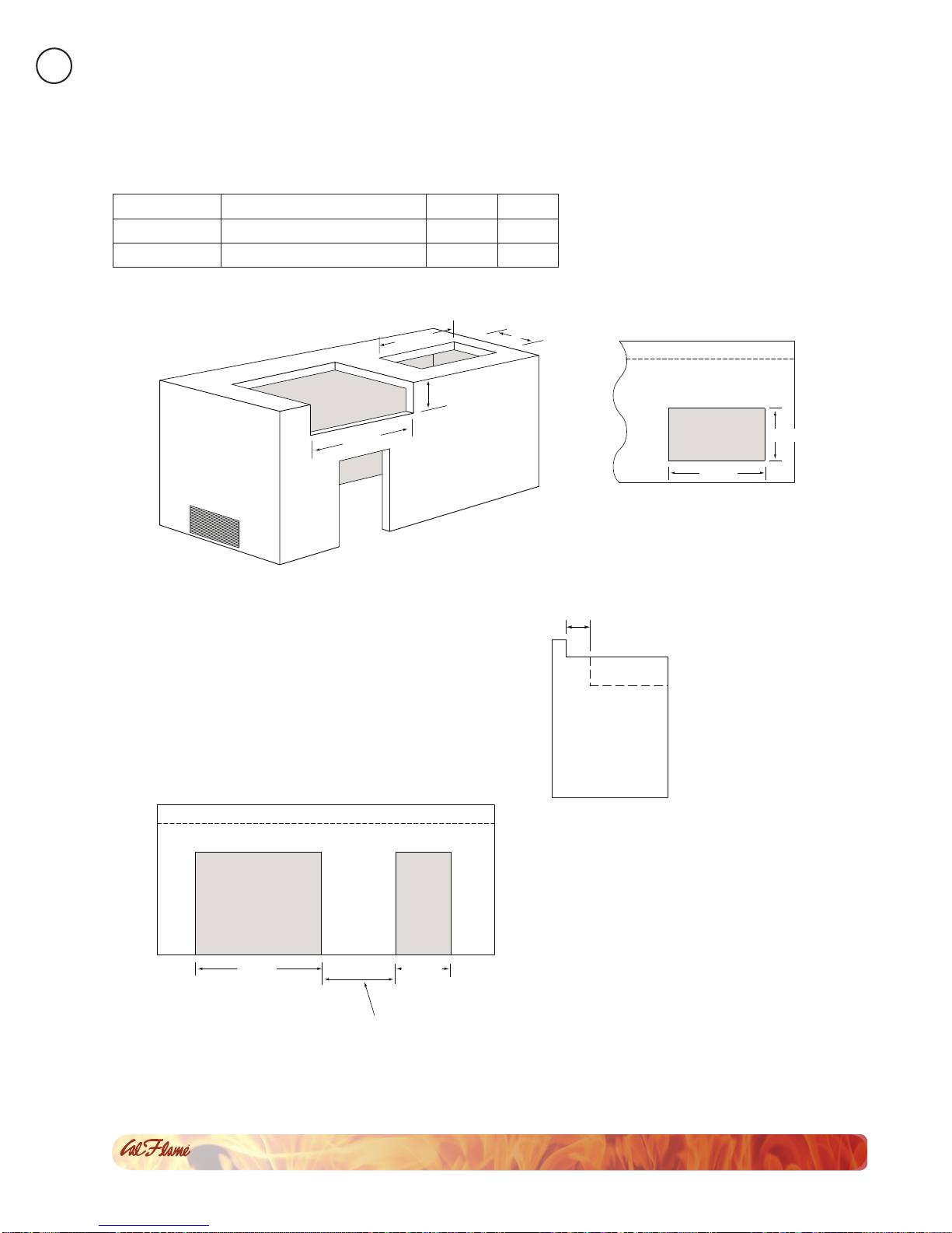
Before installing built in grills in enclosures, copy •
all product information such as model number,
serial number and type of grill (e.g. natural gas
or LP) and store information in a safe place. This
information is located on a plate located behind
Do not use grill for oth
• er than intended use.
In the event that a burner goes out, turn burner •
knobs to the full OFF position, fully open the grill
hood and let it air out. Do not attempt to use the
grill until the gas has had time to dissipate.
Never use the grill if the drip pan is not properly •
installed. Drip pan should be pushed all the way
to the rack located just under the grill. Fire or
explosion can result from an improperly installed
drip pan.
Never use the grill or side burner in windy • conditions. If used in a consistently windy area a
windbreak will be required. Always adhere to the
specied clearances listed in this manual.
Keep any electrical supply cords and the fuel •
supply hose away from any heated surfaces.
Never line the grill or side burners with aluminum foil.•
When the unit is not in use, be sure to turn off the •
gas at the LP tank.
Do not install or operate your grill unit in such •
a manner that the cross ventilation openings are
blocked. Fresh air must be able to pass though
installed vents to safeguard against residual gas
accumulation. Failure to allow proper ventilation
may cause re or explosion.

G Series Gas Grills
LTR50001050, Rev. E
Safety Instructions
www. c a l a m e b b q . c o m
2
When handling LP gas line and connectors, • do not allow them to come in contact with any
metal surfaces of the cabinet. Do not drop LP
connectors.
Do not use fuel such as charcoal briquettes in gas •
grills.
Gas sources to the grill and side burners must be •
regulated. Do not operate grill or side burners if
regulators have been removed, re or explosion
can occur.
Never leave the grill and side burners unattended •
when in use. When using pots and pans, boil-
overs will cause smoking and greasy boil-overs
may ignite.
Always use the proper size pan. Select utensils •
with at bottoms large enough to cover the burner.
The use of under-sized utensils exposes the sides
of the utensils to direct contact with a portion of
the ame. This can scorch utensils and hamper
cleanup. Excessive ames on large stainless steel
pots can result in permanent discoloration. For
best results, we recommend commercial quality
aluminum pans and utensils.
Always position handles of utensils so they do •
not extend over adjacent work areas or cooking
areas. This reduces the risk of burns, ignition of
ammable materials, and spillage due to accidental
contact with the utensils.
Do not use water on grease res. Never pick up a •
aming pan. Turn the appliance off and smother
the aming pan with a tight-tting lid, a cookie
sheet or a at tray. For aming grease outside of
the pan, smother it with baking soda or use a dry
chemical or foam-type re extinguisher.
Never allow clothing, pot holders or other •
ammable materials come in contact with or be
close to any grate, burner or hot surface until it has
fully cooled. Never wear loose tting or hanging
garments while using your grill. Fabric may ignite
and result in personal injury.
When using the grill, do not touch the grill rack, •
burner grate, or immediate surroundings as these
areas become extremely hot and can cause burns.
Use handles or knobs.
Only use dry pot holders and do not use a towel or •
other bulky cloth in place of pot holders. Moist or
damp pot holders used on hot surfaces can cause
burns.
Do not heat any unopened glass or metal container •
of food on the grill. Pressure may build up and
cause the container to burst, possibly resulting in
serious personal injury or damage to the grill.
Do not reach over your grill or any other surfaces • when hot or in use.
Spiders and other i
• nsects can nest in the burners
of the grill and block the gas and airow to the
burner ports. This creates a dangerous condition
that can result in a re behind the valve panel.
Inspect and clean the burners periodically
and follow the guidelines in the Cleaning and
Maintenance section of this manual.
Unless specically recommended in this manual, •
do not repair or replace any part of the grill. A
qualied technician should perform all service.
Any repairs made by a non-L.M.S. approved dealer
technician will void your warranty.
Maintenance and Repair
Precautions Regarding Children
Storage
When your gas grill is not in use, turn off the gas •
at the supply cylinder.
Storage of a grill indoors is permissible only if the •
supply cylinder is disconnected and removed.
Never leave children unattended in the area•
where the grill is being used. Close supervision of
children is necessary when any appliance is use
near children.
Do not store items of interest to children around•
or below the grill.
Never allow children to sit or stand on any part of •
the grill.

G Series Gas Grills
LTR50001050, Rev. E
Safety Instructions
www. c a l a m e b b q . c o m
3
Proper Location of the Grill
Cal Flame grills are designed for outdoor use
only.
Solid foundation•
Open on three sides•
Minimum distance of• six feet overhead from
combustible material
Overhead is not sealed•
Not placed near windows•
No overhead storage•
No combustible materials• stored nearby
Ensuring Proper Ventilation
Do not locate your barbecue island in an enclosed
area, which is any covered area that is walled on two,
three, or four sides. This includes areas or rooms such
as a garage, shed, breezeway, patio, cabana, etc.
Although some enclosed areas may have
windows, screens, or ventilation systems, they
are nevertheless considered to be hazardous
and may cause damage, injury,
or death. Enclosed areas are NOT
approved for a barbecue island.
Do not locate your barbecue island under a sealed
overhead structure. Acceptable overhead structures
allow for airow, such as screen or lattice.
You can install an awning over your barbecue island,
provided you make sure it is high enough to prevent
damage or re. We recommend a minimum overhead
distance of six feet from the top of the grill hood.
Carbon Monoxide Hazard
This appliance can produce carbon
monoxide which has no odor.
Using it in an enclosed
space can kill you.
Never use this appliance in
an enclosed space such as a
camper, tent, car, or home.
Here are some general considerations when
determining where to place your new barbecue island.
Be certain that your installation will meet all city and
local safety codes and requirements.
When planning your Cal Flame grill location, access
to gas lines and 110V power supplies should be
considered. If you are using natural gas, the location
with the shortest gas line run is recommended. You
may need a grounded, dedicated, 15A 110V GFCI
power source for use of your appliances (e.g. lights,
rotisserie, refrigerator, receptacles, etc.).
When determining a suitable location, consider factors
such as exposure to wind, proximity to trafc paths,
and windows that open into the home.
Locate the grill enclosure any place where there is
adequate ventilation. The size and conguration of
your house and yard will determine how you should
locate your grill enclosure, but as a general rule, do
not place it under or near windows that can be opened
into your home. Ventilation is address in greater detail
in the next section.
The sides, bottom and back of the grill enclosure
should not be any closer than 24” to combustible
construction.
To reduce the risk of personal injury caused by
reaching over a hot appliance, avoid locating cabinet
storage space directly above the outdoor grill.

G Series Gas Grills
LTR50001050, Rev. E
Built-in Construction
www. c a l a m e b b q . c o m
4Built-in Construction
Construction materials
DO NOT use combustible materials for the built-in construction.
Acceptable building materials: Brick,
cinder block, steel frame, hardiboard,
granite, tile, glass brick, concrete, cement,
stucco, stone.
Unacceptable building materials: Wood
of any sort, laminate or synthetic materials,
plastics, linoleum, berglass.
In addition, we do not recommend using materials that are susceptible to damage or decomposition by weather,
such as dry wall or plaster.
LMS Inc. will not be held responsible for property damage, injury, or death as a result of locating
a grill enclosure in a non-approved location or using non-approved construction materials.
Note: The terms “built-in construction” and “grill
enclosure” as used in these instructions refer to any
method for installing a barbecue island for use. A
barbecue island is both built-in constructions and a grill
enclosure. Read these instruction before constructing
your grill enclosure.
The Cal Flame convection grill is expected to be used
with a Cal Flame barbecue island. If the convection
grill is not placed in a Cal Flame barbecue island, it
must be used in a safe manner that will not void your
warranty. If you plan to do this, use the information in
this section on the construction and materials required
for the grill enclosure and its proper location. Cal Flame
wishes our customers to enjoy our products safely. We
strongly recommend that grill owners hire a contractor
to construct the built-in enclosure.
Failure to follow these instructions may result in voiding
your warranty, property damage, injury, or death.

G Series Gas Grills
LTR50001050, Rev. E
Built-in Construction
www. c a l a m e b b q . c o m
5
Plan the installation so that the electrical connection,
gas shut-off valve, and pressure regulator are
accessible inside the base enclosure. The gas valve
shall be readily accessible for hand operation. A door
on the enclosure to gain access to the gas valve is
acceptable, provided it is non-locking and can be
opened without the use of tools.
The design of the outdoor cooking enclosure must allow
the LP gas cylinder to be connected and disconnected
and the connections inspected and tested.
There must be a minimum clearance of 2 inches
(51mm) between the oor of the LP-gas cylinder
enclosure and the ground.
Model Description Width Depth Height
BBQ09G03 G3 three burner grill 23 3/8” 22” 9 ¼”
BBQ08G04 G4 four burner grill 31” 22” 9 ¼”
BBQ09G05 G5 ve burner grill 38 7/8” 22” 9 ¼”
W
ID
T
H
W
ID
T
H
W
ID
T
H
W
ID
T
H
Minimum
Clearance
12” Minimum Distance
Between Grill and Side Burner
Minimum
Clearance
Screen Vents
WIDTH
W
ID
T
H
WIDTH
DEPTH
WIDTH
WIDTH
DEPTH
WIDTH
WIDTH
WIDTH
DEPTH
DEPTH
DEPTH
HEIGHT
HEIGHT
HEIGHT
Burner
Locking Pin
Burner
Locking Pin
Model Description Width Depth Height
BBQ08954P Deluxe Side by Side Burner 25 ¼” 12 ½” 7 ¼”
BBQ08899P Deluxe Double Side Burner 12 ¼” 22” 7 ¼”
The dimensions shown below are for Cal Flame appliances only.
Built-in Dimensions

G Series Gas Grills
LTR50001050, Rev. E
Built-in Construction
www. c a l a m e b b q . c o m
6
W
ID
T
H
W
ID
T
H
W
ID
T
H
W
ID
T
H
Minimum
Clearance
12” Minimum Distance
Between Grill and Side Burner
Minimum
Clearance
Screen Vents
WIDTH
W
ID
T
H
WIDTH
DEPTH
WIDTH
WIDTH
DEPTH
WIDTH
WIDTH
WIDTH
DEPTH
DEPTH
DEPTH
HEIGHT
HEIGHT
HEIGHT
Burner
Locking Pin
Burner
Locking Pin
W
ID
T
H
W
ID
T
H
W
ID
T
H
W
ID
T
H
Minimum
Clearance
12” Minimum Distance
Between Grill and Side Burner
Minimum
Clearance
Screen Vents
WIDTH
W
ID
T
H
WIDTH
DEPTH
WIDTH
WIDTH
DEPTH
WIDTH
WIDTH
WIDTH
DEPTH
DEPTH
DEPTH
HEIGHT
HEIGHT
HEIGHT
Burner
Locking Pin
Burner
Locking Pin
Model Description Width Depth
BBQ08953P Side By Side Flat Burner 24 ¼” 19 ¾”
BBQ08852P Single Flat Side Burner 11 ½” 17 ¾”
WIDTH
WIDTH
WIDTH
WIDTH
Minimum
Clearance
12” Minimum Distance
Between Grill and Side Burner
Minimum
Clearance
Screen Vents
WIDTH
WIDTH
WIDTH
DEPTH
WIDTH
WIDTH
DEPTH
WIDTH
WIDTH
WIDTH
DEPTH
DEPTH
DEPTH
HEIGHT
HEIGHT
HEIGHT
Burner
Locking Pin
Burner
Locking Pin
WIDTH
WIDTH
WIDTH
WIDTH
Minimum
Clearance
12” Minimum Distance
Between Grill and Side Burner
Minimum
Clearance
Screen Vents
WIDTH
WIDTH
WIDTH
DEPTH
WIDTH
WIDTH
DEPTH
WIDTH
WIDTH
WIDTH
DEPTH
DEPTH
DEPTH
HEIGHT
HEIGHT
HEIGHT
Burner
Locking Pin
Burner
Locking Pin
The back edge of the grill must maintain a minimum
clearance of 8” from non-combustible back splash
materials.
The dimensions shown below are for Cal Flame appliances only.
Top view of enclosure
with back splash
Side view of enclosure
with back splash
Top view of enclosure
with back splash

G Series Gas Grills
LTR50001050, Rev. E
Built-in Construction
www. c a l a m e b b q . c o m
7
For proper ventilation, the base structure must be constructed using one of two designs:
An enclosure having four sides, a top, and bottom
1
2
An enclosure with one side open
The second type of enclosure must be constructed
with the following specications:
At least two ventilation openings at cylinder
•
valve level shall be provided in the side wall,
equally sized, spaced at 180 degrees and
unobstructed.
Each opening shall have a total free area of not •
less than 10 square inches (254 square mm).
Ventilation openings shall be provided at oor • level and shall have a total free area of not less
than 10 square inches (254 square mm). If the
ventilation openings at oor level are in a side
wall, there shall be at least two openings. The
bottom of the openings shall be at oor level and
the upper edge no more than 5 inches (127mm)
above the oor. The openings shall be equally
sized, spaced, and unobstructed.
LP-gas cylinders should be ventilated by •
openings at the level of the cylinder valve and
the oor level. The effectiveness of the openings,
for purposes of ventilation, shall be determined
with the LP-gas supply cylinder in place.
Enclosure Ventilation

G Series Gas Grills
LTR50001050, Rev. E
Gas and Electrical Supply Requirements
www. c a l a m e b b q . c o m
8Gas and Electrical Supply Requirements
Gas Requirements and Connection
IMPORTANT: The Cal Flame grill is manufactured to operate on liquid propane (LP). However, it can be
converted to operate on natural gas (NG) by an authorized service technician.
This barbecue grill does not include the parts for converting to NG. The gas conversion kit can be ordered
separately. The part number for the conversion kit is BBQ07101045. Grill conversion instructions can be
found on page 29 and ordering information can be found in this manual on page 32.
Gas Requirements
Tank Requirements
For plumbed-in LP installation, use a convertible
regulator and set it for LP gas.
Maximum line pressure for plumbed-in propane
is 14” WC (3.5 kPa). Minimum line pressure for
propane is 11” WC.
The grill must be used with the gas pressure regulator.
The regulator will control and maintain a uniform
gas pressure in the manifold. The burner orices
have been sized for the gas pressure delivered by
the regulator.
WARNING: Attempting to operate the grill unit
without the gas regulator installed could cause an
explosion and possible death.
CylinderSpecication
The LP cylinder must be constructed and marked
in accordance with the Specications for LP-Gas
Cylinders of the U.S. Department of Transportation
or the National Standard of Canada, CAN/CSA-
B339, Cylinders, Spheres and Tubes for
Transportation of Dangerous Goods; and
Commission, as applicable.
Any LP gas supply cylinder used with this grill must
be approximately 12 inches in diameter and 18 inches
high.
The maximum fuel capacity is 20 lbs. of propane, or 5
gallons. Full cylinder weight should be approximately
38 lbs. (43.7 lbs. nominal water capacity.) Never ll
the cylinder beyond 80% full.
If you do not have an updated ller valve on your
existing propane tank, you will need to purchase one
at your local hardware store. Without it you will not
be able to attach your tank to your grill or rell the
tank at your local propane rell station.
Transporting and Storing LP Gas
Transport only one cylinder at a time. Ensure the
cylinder is secured in an upright position with the
control valve turned off and the dust cap in place.
Store cylinders outdoors and out of reach of children.
Do not store cylinders in a building, garage, or any
other enclosed area.
Place the dust cap on the cylinder valve outlet whenever
the cylinder is not in use. Only install the type of dust
cap on the cylinder valve outlet that is provided with
the cylinder valve. Other types of caps or plugs may
result in leakage of propane.
Liquid Propane

G Series Gas Grills
LTR50001050, Rev. E
Gas and Electrical Supply Requirements
www. c a l a m e b b q . c o m
9
Natural Gas
NG Service Installation and Connection
Natural gas installation of this appliance must conform
with local codes or, in the absence of local codes,
to the national fuel gas code, ANSI Z223.1a-1998.
Installation in Canada must be in accordance with
the standard CAN/CGA-B149.2, Propane Installation
Code.
You do not need to hire a contractor to install your
natural gas service, but you need to make sure you
have all required permits and ensure the installation
complies with State and local code. We recommend
you hire a certied contractor if you do not wish to do
the installation yourself.
The natural gas pipe from your house to the
location of your barbecue island needs to be ¾” and
terminate with a shut-off valve with a ½” male tting.
Check with a contractor or your local inspector for
requirements.
Always check the rating plate to make sure the gas
supply you are hooking up to is the gas type the grill
is manufactured for.
NG Regulator
The grill for use with natural gas comes equipped
with its own regulator that MUST NOT be removed.
If this regulator needs to be replaced, use only the
type specied by for this appliance.
IMPORTANT: Never connect the grill to an
unregulated gas supply.
Shut-off Valve
Ensure that the service supplying the grill is tted
with a shut off valve conveniently positioned near
the grill and giving ease of access.
The grill must be isolated from the gas supply piping
system by closing its individual manual shutoff valve
during any pressure testing of the gas supply piping
system at test pressures equal to or less than 0.5
psi (3.5 kPa).

G Series Gas Grills
LTR50001050, Rev. E
Gas and Electrical Supply Requirements
www. c a l a m e b b q . c o m
10
Electrical Supply Requirements
You will need a dedicated 120V 10 amp grounded
electrical service. The power supplied to your grill
enclosure must be on a dedicated circuit with no other
appliances or lights sharing the power.
You do not need to hire a contractor to install your
electrical service, but you must ensure you have
all required permits and the installation complies
with State and local code. We recommend you hire
a certied contractor if you do not wish to do the
installation yourself.
If your dealer is not a certied contractor, you will need
to hire a contractor for installation of your electrical
service.
When installed in the United States, the electrical
wiring must meet the requirements of National Electric
Code, ANSI/NFPA 70-1999 and any applicable state
or local codes. The electrical circuit must be installed
by an electrical contractor and approved by a local
building / electrical inspector.
To determine the current, voltage, and wire size
required for the island conguration to be connected,
refer to the following:
Wire size is determined by length of run from •
breaker box to the barbecue island and maximum
current draw.
We recommend copper wire with THHN • insulation.
All wiring must be copper to ensure adequate • connections. Do not use aluminum wire.
When NEC requires the use of wires larger than #6 •
(10mm²), install a junction box near the barbecue
island and use #6 (10mm²) wire between the
junction box and the grill enclosure.

G Series Gas Grills
LTR50001050, Rev. E
Installation and Connection
www. c a l a m e b b q . c o m
11
Installation and Connection
Connecting the Grill and Side Burner
These instructions show you how to connect a grill only or a grill and side burner combination.
If you plan to convert to your grill from LP to NG, you need to do this before it is connected to a gas source.
Grill conversion instructions can be found on page 29 and ordering information can be found in this manual on
page 32. There are a few differences between connecting to LP and NG.
You will need a second
person to help you to avoid
damaging the grill or your
barbecue island.
Before installing a grill or side
burner in any island or cut out,
make sure that the opening is
not bigger than the outside
frame of the grill unit. The grill
should rest on the lip of the
frame. For drop-in accessories,
adequate cross ventilation must
be designed into enclosure
to ensure the drop-in grill or
side burner does not become
overheated.
Pay careful attention to the
location of gas lines. Gas lines should be routed
away from sources of heat and should make as few
bends as possible.
Check to see if gas line connections will be accessible
when grill is installed.
If gas line connections are not easily accessible •
when the grill is installed, support the grill above
counter level and attach the gas lines to the grill.
When the gas connections are made, slide the
grill into the cut out.
If gas line connections are accessible when the •
grill is installed, slide the grill into the cut out
and then attach the gas lines.
1. Place the Grill and Side Burner in the Cut-outs
Be very careful not to kink gas lines when lowering the
grill or side burner into the cut out.
Keep your ngers away from where the grill will be
supported on counter. Your ngers could become
trapped and serious injury could occur.
Check to make sure the grill is level and is supported
around the entire outside edge. If the grill is not level
or is unstable, use non-combustible shims under the
outside lip to stabilize it.
Perform the leak test procedure as described earlier
in this manual.

G Series Gas Grills
LTR50001050, Rev. E
Installation and Connection
www. c a l a m e b b q . c o m
12
2. Connect the Gas Line to the Grill
Note: Make sure you have converted the grill for natural gas before connecting the gas line to the regulator.
See page 29 for instructions on converting the grill from LP to NG.
Connecting the grill only
If you have a grill and side burner combination, go
to step 2.2.
Slide the grill forward about six inches and connect the
gas line to the grill using the appropriate connection
for your gas type.
Natural Gas
Liquid Propane

G Series Gas Grills
LTR50001050, Rev. E
Installation and Connection
www. c a l a m e b b q . c o m
13
Note: This is only necessary if you
have a side burner.
a. Assemble the T Connection
Items required for connection (NOT
included with your grill):
One 3/8” T adapter•
One or two 1/2” to 3/8” are • reducers
Two 3/8” ex lines•
LP gas line with regulator OR •
3/8” NG ex line
Connect two 3/8” ex lines to the
ends of the T connector that will
connect with the grill and side
burner. Connect either a third ex
line (if you are using NG) or a LP
gas line (if you are using LP) to
the third end of the T connector as
shown at left.
b. Connect to the grill
The gas manifold for the convection
grill can be congured for both LP
and NG. Make sure you connect
to the correct tting depending on
your gas type. Connect to gas line
to the grill as shown in step 3.1
above.
c. Connect to the side burner
Connect the ex line from the T
connector to the 1/2” to 3/8” are
reducer tting on the side burner gas line. No regulator is required for either LP or NG.
Connect to
NG gas source
3/8” tee adapter
3/8” flex line 3/8” flex line
Connect to grill
Connect to
side burner
3/8” flex line
NG CONNECTION
IIIII
IIIII
IIIIIIIIIIIIIIII
IIIII IIIII
IIIII
1/2” to 3/8” reducer
Connect to
propane tank
3/8” tee adapter
3/8” flex line
3/8” flex line
1/2” to 3/8” reducer
I
I
I
I
I
I
I
I
I
I
I
I
I
I
I
Connect to grill
Connect to
side burner
Black LP gas line
with regulator
LP CONNECTION
IIIII
IIIII IIIII
IIIII
3. Connect the Gas Line to the Grill and Side Burner

G Series Gas Grills
LTR50001050, Rev. E
Installation and Connection
www. c a l a m e b b q . c o m
14
Perform a leak test at least once a year whether the
gas supply cylinder has been disconnected or not. In
addition, whenever the gas cylinder is connected to
the regulator or whenever any part of the gas system
is disconnected or replaced, perform a leak test.
As a safety precaution, remember to always leak test
your grill outdoors in a well-ventilated area. Never
smoke or permit sources of ignition in the area while
doing a leak test. Do not use a ame, such as a
lighted match to test for leaks. Use a solution of
soapy water.
Prepare a leak testing solution of soapy water by 1. mixing in a spray bottle one part liquid soap to
one part water.
Make sure all the control knobs are in the OFF 2. position.
Turn on the gas.3.
Ona. natural gas systems, turn the main feed
valve to the grill.
Onb. LP systems, turn the cylinder valve knob
counter clockwise one turn to open.
Apply the leak-testing solution by spraying it on 4. joints of the gas delivery system. Blowing bubbles in
the soap solution indicates that a leak is present.
Stop a leak by tightening the loose joint or by 5. replacing the faulty part with a replacement
part recommended by the manufacturer. Do
not attempt to repair the cylinder valve if it is
damaged. The cylinder must be replaced.
Turn all control knobs back to the full OFF 6. position.
If you are unable to stop a leak:
Turn all control knobs back to the full OFF 1. position.
Shut off the gas supply to the grill and release 2. pressure in the hose and manifold by pushing in
and turning any of the control valves one quarter
turn counter-clockwise.
On LP systems, remove the cylinder from the3.
grill.
Call an authorized gas appliance service technician 4. or an LP gas dealer.
Do not use the appliance until the leak is corrected.
4. Connect to a Gas Source
Leak Testing Procedure
Liquid Propane Connection
Use the pressure regulator and hose assembly supplied
with the grill, or a regulator and hose assembly with
the same specications. Replacement LP regulator and
hose must have a coupling nut that will connect to a
QCC-1 cylinder valve on one end and a female tting
that will connect to a 3/8” tapered tting on the grill
manifold. See the gures below.
Connect the brass tting to the manifold behind the
grill. Do not use Teon tape or plumber’s dope. Do NOT
remove the NG regulator from the manifold. Connect
the coupling nut to the LP cylinder valve.
When you are nished connecting to the gas source, perform a leak test.
Natural Gas Connection
Connect the gas line to the NG stub-up inside the barbecue island. When you are nished connecting to the
gas source, perform a leak test.

G Series Gas Grills
LTR50001050, Rev. E
UsingYour Grill
www. c a l a m e b b q . c o m
15
Using Your Grill
Read all instructions before you operate your grill.
We recommend you wash your entire grill with soap
and water prior to lighting it for the rst time. Oils
are used during the manufacturing process and some
residual oil may still be on the stainless steel parts
of your grill. Washing will reduce the possibility of
discoloration. We also recommend you keep your
grill covered when not in use. This will minimize the
amount of dust and dirt that accumulates on your grill
and extend the life of your grill.
Remember to use your Cal Flame grill safely by
following these reminders:
It is dangerous to use barbecue grills and side •
burners in any manner other than for what it is
designed for.
Do not use charcoal in a gas grill or side burner.•
Do not heat sealed containers such as cans or jars •
on grills or side burners. Explosion may result
resulting in injury or death. Any sealed container,
such as a pressure cooker, must have a properly
operating pressure relieve valve to minimize
explosion hazard.
Never put combustible material such as paper, •
cloth, or ammable liquids on your grill at any time.
Do not use grill, side shelves, cabinets, or any area
around grill to store ammable materials.
Basic Grill Operation
Before lighting, make sure all burner controls are off.
Do not attempt to light the burners if the smell of
gas is present. Check the connection with a soap and
water solution after attaching the hose. For LP units,
make sure there is gas in the tank and it is sitting
upright. For natural gas units, make sure the shut off
valve is on.
Make sure the drip tray is in place.1.
Light the grill burners using the instructions on the 2. previous page.
Turn the control knob to HIGH and preheat the 3.
grill for 15 minutes. Close the top cover during
the appliance preheat period.
Place the food on the grill and cook to desired 4. completion. Adjust heat setting if necessary. You
may set the control knob to any position between
HIGH and LOW.
Allow the grill to cool and clean the drip tray after 5. each use.
Do not leave the grill unattended while cooking.
Warning
NEVER cover the entire cooking or grill surface with griddles or pans. Overheating will occur and burners
will not perform properly when combustion heat is trapped below the cooking surface.
CAUTION: NEVER spray water on a hot gas unit. This may damage porcelain or cast iron components.

G Series Gas Grills
LTR50001050, Rev. E
UsingYour Grill
www. c a l a m e b b q . c o m
16
Each time you light the grill, check the following:
Inspect the hose before using the grill. If there is •
excessive abrasion or wear, or if the hose is cut,
it must be replaced prior to using the grill. See
page 8 for LP connection instructions and speci-
cations. If you need a replacement hose, contact
your Cal Flame dealer.
Ensure the area around the barbecue is clear of •
ammable substances such as gasoline, yard de-
bris, wood, etc.
Ensure there is no blockage of the airow through •
the vent space located below the face of the unit.
When using propane gas, keep the special venti-•
lation openings in the enclosure free and clear of
debris.
If connected to a propane cylinder, carefully in-•
spect the rubber hose attached to the regulator
before each use.
Ensure the propane cylinder, regulator, and rubber •
hose are installed in a location not subject to heat-
ing above 125º F (51º C).
Ensure the burner ames burn evenly along both •
sides of each burner with a steady ame (mostly
blue with yellow tipping). If burner ames are not
normal, check the orice and burner for insects or
insect nests.
Ensure the in-line gas valve or gas cylinder valve •
is always shut OFF when the barbecue is not in
use.
Do not operate the side burner with its cover •
closed or the back burner with its cover installed.
Lighting the Burners
Electronically Lighting the Burners
Open the hood.1.
Keep your face as far away from the burners as 2. possible.
Press and rotate the burner knob counter 3.
clockwise past the light position to HIGH. You
will hear a loud click as the electronic lighter
produces a spark.
Listen for the sound of the gas igniting. If the 4. burner does not light on the rst try, repeat
immediately.
If the burner does not light after three attempts, 5. turn the control knobs to the OFF position. Wait
ve minutes until the gas clears before attempting
to light it again.
Repeat the procedure or try the manual lighting 6. procedure below.
Upon successful lighting, repeat the process on 7. the other burners you wish to light.
To shut off the burners, rotate the knob and turn 8.
to OFF. It is normal to hear a popping sound
when the burners are turned off.
Grill Controls
4
3
Burners 2
1Grill Knob Operaon
Low
Off
High
The controls shown below are for the G4 grill. Familiarize yourself
with these controls before using your Cal Flame™ barbecue.

G Series Gas Grills
LTR50001050, Rev. E
UsingYour Grill
www. c a l a m e b b q . c o m
17
Manually Lighting the Burners
WARNING: Do not use standard matches or cigarette
lighters to perform match lighting procedures. Serious
burns can occur and lighters can explode.
Open the hood.1.
If you have just attempted to light the burner, 2. allow ve minutes for any accumulated gas to
dissipate.
Slide out the drip tray from the grill.3.
Keep your face as far away from the burners as 4. possible.
Light and insert a long stem match, holding it 5.
near the burner ports.
Push in and turn the control knob just past the 6. LIGHT position to HIGH.
Listen for the sound of the gas igniting. If the 7. burner does not light after ve seconds, turn
the control knobs to the OFF position. Wait ve
minutes until the gas clears before attempting to
light it again.
If the burner does not light after several attempts 8.
see Troubleshooting Guide in the back of this
manual.
Proper Burner Flame
The burner ame has been set in the factory and
should already be adjusted for proper height and
intensity. Periodically, you may wish to check each
burner’s ame for color, height, and intensity.
Remove the grill rack and the ame tamer over the
burner you want to inspect.
When the burner is operating properly, the ame will
appear between light to dark blue, with occasional
yellow bursts (due to impurities in propane -- this is
normal).
When the burner is set on high, the ame spread
out about ½” away from the side of the burner. (See
top gure at right.)
When the burner is set on low, the ame should be
just slightly visible when viewed from the side. (See
bottom gure at right.)
Note: Flame that is mostly yellow or golden in color
is often due to foreign matter in the burner. You
may need to clean your burners. See page 25 for
instruction on removing and cleaning your burners.
Flame Color and Height

G Series Gas Grills
LTR50001050, Rev. E
UsingYour Grill
www. c a l a m e b b q . c o m
18
Heat Distribution on the Cooking Grates
When you place food your Cal Flame grill,
remember that the back of the grill tends to
be hotter than the front.
As your food cooks, you should periodically
shift it to different spots on the cooking grates
to ensure everything cooks evenly without
burning.
Flame Adjustment
You can adjust the ame height to be higher or lower
according to your preferences. This may be necessary
if the ame goes out on the low ame setting.
Light the burner and adjust the ame as low as it 1. can go without going out.
Remove the knob and insert a long at standard 2. screwdriver into the hole at the lower right side of
the valve.
Turn the ame adjustment screw to adjust the 3.
ame to your preference.
Gas Cylinder Orientation
LP gas cylinder must be up oriented upright during operation for proper vapor withdrawl. Operating the grill
with the cylinder on it side will allow liquid gas to ow into the regulator. Erratic gas ow will occur, resulting
in possible are-ups or explosion.
This manual suits for next models
2
Table of contents
Other LMS Grill manuals
Popular Grill manuals by other brands

tepro
tepro HARTFORD instruction manual

Camp Chef
Camp Chef PG24CLAU Warning & instruction booklet

Gasmate
Gasmate ODYSSEY2T BQ1062 manual

Mayer Barbecue
Mayer Barbecue MKG-122 MASTER Assembly instructions

PERMASTEEL
PERMASTEEL PG-50601SRLA-1 user manual

Cosori
Cosori VeSync Aeroblaze CAG-A601S Series user manual