6
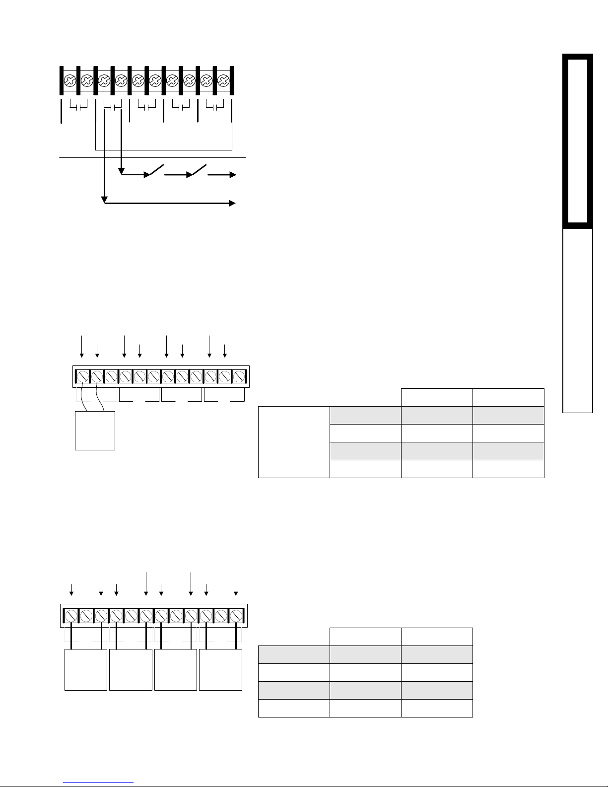
• The System Prove feature is provided to check system component
operation.
• A typical use of this feature is to check for flow before firing any
boiler stages. When there is a call for heat, the System Output
activates the system pump starter. When the pump establishes flow,
a flow switch closes together the SYSTEM PROVE input. Only then
can the Harmony activate boilers and modulate them as required to
hold the temperature set point.
• If the SYSTEM PROVE input is open on a call, the Harmony will
enable only the System Output. All Stage outputs will be off when
the SYSTEM PROVE input is open.
• A factory installed jumper provides the System Prove signal. Do not
remove the jumper unless it will be replaced by a System Prove
signal.
• The System Prove signal must be a dry contact only. No voltage can
be placed across the SYSTEM PROVE - A9, A10 terminals.
• Bring the two wires from the dry contact to the terminals marked
SYSTEM PROVE - A9,A10.
IMPORTANT: DonotremovethefactoryinstalledSystemProve
jumperunless it isreplaced by aSystemProve signal. Ifthe
SYSTEMPROVEinputisnotclosed,theHarmonywillNOT
activatestages.
WIRING THE BOILER ACTIVE INPUTS
• A closure across the BOILER ACTIVE terminals informs the Har-
mony that a boiler is running normally. If the BOILERACTIVE
terminals open, the Harmony registers that the Stage has encoun-
tered a safety limit and can not be restarted without a manual reset.
The Harmony will not reactivate or modulate a Stage which is not
Active.
• The Boiler Active signal is not a safety, but use of these inputs will
significantly improve the Harmony's set point control performance in
the event of a Stage encountering a safety limit.
• A pair of BOILER ACTIVE terminals is provided for each stage.
• The Boiler Active signal must be a dry contact closure from the
boiler controlled by that Stage's output. For example, the Boiler
Active signal wired into terminals STAGEA (Terminals B1 and B2)
must come from the unit whose operating limits are connected to
terminals OPERATING LIMIT OUTPUTS A(Terminals 5and 6).
• The BOILER ACTIVE terminals are dry contacts only. No voltage
can be placed across the them.
• Wire the BoilerActive signals to their respective STAGE terminals:
- STAGE A to BoilerActive Input terminals B1&B2
-STAGE B to BoilerActive Input terminals B3&B4
- STAGE C to BoilerActive Input terminals B5&B6
- STAGE D to BoilerActive Input terminals B7&B8
Dry Contact
System Prove
Signal
TEMP
SHUTDOWN
NETWORK
SYSTEM
PROVE
T
+
S
INPUTS
A1
A2
A3
A4
A5
A6
A7
A8
A9
A10
WARNING: The SYSTEM PROVE
input can not be used as a safety
limit. All equipment must have its
own certified limit and safety con-
trols as required by local codes.
STAGE
A
STAGE
B
STAGE
C
STAGE
D
Dry Contact
Active Signal
INPUTS
B1
B2
B3
B4
B5
B6
B7
B8
BOILER
ACTVE
WARNING: The BOILER ACTIVE IN-
PUTS can not be used as a safety
limits. All equipment must have its
own certified limit and safety con-
trols as required by local codes.
INSTINST
INSTINST
INSTALLAALLA
ALLAALLA
ALLATIONTION
TIONTION
TION INPUT WIRINGINPUT WIRING
INPUT WIRINGINPUT WIRING
INPUT WIRING

L 030 Application guide")


 User manual")


 null")
 null")


 Operation and maintenance instructions")