Loctite LOCTITE 97715 User manual

Operating Manual
Bedienungsanleitung
Finespray Applicator HVLP, Extensions
Feinsprühpistole HVLP, Verlängerungen
97715/97725

2
Content
English
1 Please observe the following................................................................. 3
1.1 Emphasized Sections ............................................................................... 3
1.2 Items Supplied .......................................................................................... 3
1.3 Field of Application (Intended Use)........................................................... 3
1.4 For Your Safety......................................................................................... 4
2 Description.............................................................................................. 6
3 Technical Data......................................................................................... 7
4 Setup and Operation............................................................................... 7
4.1 Setup ........................................................................................................ 7
4.2 Operation.................................................................................................. 8
4.3 Shutdown.................................................................................................. 8
4.4 Return to Operation .................................................................................. 8
5 Care and Maintenance............................................................................ 9
5.1 Care.......................................................................................................... 9
5.2 Changing Nozzle....................................................................................... 9
5.3 Disassembling Valve-Needle .................................................................... 9
6 Troubleshooting.................................................................................... 10
7 Annex..................................................................................................... 11
7.1 Spare Parts Finespray Applicator 97715/97725...................................... 11
7.2 Spare Parts Extensions .......................................................................... 11
7.3 Accessories............................................................................................. 12
Deutsch.................................................................................................. 14

3
1 Please observe the following
1.1 Emphasized Sections
Warning!
Refers to safety regulations and requires safety measures that protect the operator
or other persons from injury or danger to life.
Caution!
Emphasizes what must be done or avoided so that the unit or other property is not
damaged.
As a result of technical development, the illustrations and descriptions in this
operating manual can deviate in detail from the actual unit delivered.
The numbers printed in bold in the text refer to the corresponding position numbers
in the illustration on page 6.
•The point emphasizes an instruction step.
1.2 Items Supplied
1 Finespray Applicator 97715 or 1 Finespray Applicator HVLP 97725
1 Duo Tube, assembled,
1Operating Manual or
1 Finespray Applicator with Extension
1 Duo Tube, assembled,
1 Operating Manual
1.3 Field of Application (Intended Use)
The Finespray Applicators 97715 and 97725 are high performance spray
applicators and precision tools. They are designed for finest applications of low
viscose Loctite Frekote®products. To the difference to the 97715, the 97725 is a
High Volume Low Pressure applicator. The HVLP applicator 97725 is working with
lower input and jet pressure and with higher air volume. The atomized spray (jet) is
considerable finer and the overspray is lower.
The applicator 97715 has a 90° flat fan, 97725 a 60° flat fan air cap.
It is not suitable for spraying aggressive fluids, like acids, alkaline solutions,
cleaning agents (chlorinated hydrocarbons) or chemicals.
Always keep clean and observe minimum instructions to maintain a long useful life
of the applicator.
Depending on viscosity of fluid the following nozzle bores are available:
∅0.3 and ∅0.8 mm (only one size of air cap is required).
– The standard version of the Finespray applicator 97715 has a nozzle bore of
0.5 mm and flat spray pattern air cap with approx. 90° spray angle.
– The standard version of the Finespray applicator HVLP 97725 has a nozzle bore
of 0.5 mm and flat spray pattern air cap with approx. 60° spray angle.
If round spray is required, just replace air cap by a round spray air cap.
Flat spray air cap can be positioned for horizontal, vertical or any in between
position of jet.
For special air caps with other spray angles please contact your LOCTITE
representative.

4
1 Please observe the following
1.4 For Your Safety
For safe and successful operation of the unit, read these instructions completely.
The manufacturer cannot be held responsible for damage or injury of any kind
because of misuse or improper application or because of failure to observe safety
instructions or warnings.
Be sure to retain this manual for future reference.
Request the technical data sheet and the safety data sheet (acc. to the EC Directive
91/155/EC) for the LOCTITE Frekote®-product used at
Henkel Loctite Deutschland GmbH
www.loctite.com for US and Canada version of data sheets
+49 89 92 68 11 67 for English version of data sheets;
089-92 68 11 22 for German version of data sheets.
FOLLOW UNCONDITIONALLY THE INSTRUCTIONS OF THESE DATA SHEETS!
Unconditionally Instructions in Handling
1 If ventilation is insufficient, wear
suitable respiratory equipment!
2 Wear impermeable and chemical
resistant protective clothing and
apron!
3 Wear tight-fitting safety goggles!
4 Wear protection gloves!
5 Do not smoke!
Read and understand operator's manual before using this machine. Failure to follow
operating instructions could result in injury or damage to equipment.
If chemical products are not properly handled, damage to health can result!
Observe general safety regulations for the handling of chemicals!
Observe manufacturer’s instructions!
Do not use any solvents, cleaning liquids or coating materials containing 1,1,1
Trichlormethane or Methylen Chloride i.e. agents of the group of chlorinated
hydrocarbons. These chemicals may react with aluminium, anodised or zinced
parts. The chemical reaction may be explosive.
Danger caused by combustible and noxious spraying material. Safety instructions
on fluid can and material data of fluid manufacturer must definitely be observed.
12
35
4

5
1 Please observe the following
Never point the spray applicator against persons.
Spraying procedures cause noise depending on the used pressure.
If necessary, wearing of ear protection is recommended.
Keep unprotected persons away.
Avoid spilling or spraying in enclosed areas.
Use only in well-ventilated areas.
Provide adequate ventilation, also at floor level (vapors are heavier than air).
Provide processing equipment with adequate local exhaust ventilation.
Protect from heat and direct sunlight.
Do not spray on naked flames or any incandescent material.
– Keep away from sources of ignition.
Irritating to eyes, respiratory system and skin.
In case of contact with eyes, rinse immediately with plenty of water and seek
medical advice. Consult the relevant Safety Data Sheet for the product you are
using.

6
2 Description
The spray applicators 97715/97725 have been thoroughly tested before leaving
Loctite. No more adjustments are necessary prior to setting up spray operation.
1 Protection Ring
2 Air Cap at 97715 (90° flat fan) and 97725 (HVLP 60° flat fan).
3 Nozzle, standard is a 0.5 mm nozzle made of stainless steel.
4 Spray applicator body with trigger lever, pressurized air and agent
connections.
5 Needle Gasket (PTFE).
6 Stuffing Box
7 Needle, stainless steel.
8 Needle Nuts, M2.
9 O Ring 4.7 * 1.42 mm.
10 Valve Gasket
11 Valve Spring
12 Needle Spring
13 Valve Lock
14 Locking Screw
15 Needle Regulator with Counter Nut
16 Pressurized Air Fitting “AIR” for tube, blue, OD 6 mm, ID 4 mm.
17 Agent Fitting “M” for tube, clear, OD 6 mm, ID 4 mm.
1234
5678910 1112 1314
M
M
AIR
15
1617

7
3 Technical Data
Quality: If the required quality
is not achieved, install a
LOCTITE separator.
Filtered 10 µm, oil-free, non-condensing.
Accessory Order No. 97714
Max. Air Pressure 6 bar (87 PSI)
Max. Agent Pressure 1.5 bar (29 PSI),
see operating manual pressure pot.
Air Consumption App. 90 l/min at 3 bar (43 PSI) and 0.5 mm
nozzle
Weight 0.240 kg
Length Duo Tube ~ 3 m (~10 ft)
4 Setup and Operation
Pay attention to the safety instructions in section 1.4 “For your Safety”.
4.1 Setup
If fluid output requires to be regulated individually, apply needle regulator with
counter nut 15 for quantity of fluid flow. To spray with a spray applicator a definite
volume of atomizing air and a definite pressure of materials is needed. Activating
the trigger will open the needle and the material flows out of from the nozzle. The air
pressure atomizes the material and forms it to a jet.
The needle function is: Opening by trigger and closing by spring force.
•Connect duo tube to pressure pot or other means of feeding fluid and to main air
supply.
Clear tube: for agents, connection M 17.
Blue tube: for air pressure, connection AIR 16.
•Set air pressure to required spray droplet size by the regulator for pressurized air
at the pressure pot, see operating manual pressure pot.
•Set agent pressure to required material outlet and spray droplet size by the
regulator for agents at the pressure pot, see operating manual pressure pot.

8
4 Set Up and Operation
4.2 Operation
Fluid output can be regulated individually. Apply needle regulator with counter
nut 15 for quantity of fluid flow.
Turning needle regulator right: less fluid flow.
Turning needle regulator left: more fluid flow.
•Pull trigger at the valve body 4. Spray operation starts.
You will notice that you receive so called “pre-air” prior to opening fluid flow when
pulling the trigger. When releasing trigger you still have “purging-air” after needle
has closed, nozzle and fluid flow Has stopped. This prevents that the fluid forms
drops instead of the desired atomization.
4.3 Shutdown
•Hold up the finespray applicator.
•Depressurize the pressure pot.
The mold release agent flows back into the pressure pot.
4.4 Return to Operation
•Pressurize the pressure pot.
•Pull trigger at the valve body 4. Spray operation starts.
The feedline will be filled.
9
5 Care and Maintenance
5.1 Care
Pay attention to the safety instructions in section 1.4 “For your Safety”:
Before servicing the spray applicator
– Disconnect it from the material supply and
– Release air pressure.
Otherwise ejected elements can cause danger.
To clean the applicator, spray solvent until pure solvent leaves nozzle. Do not
submerge entire applicator in solvent. At longer working interruptions it is advisable
to clean air cap and nozzle by putting these parts only into solvent. If necessary,
use soft brush. To clean small drill holes, use our special nozzle cleaning needles
(Sealing and Repair Kit 97730). Moving parts and threads should always be
greased slightly.
5.2 Changing Nozzle
A nozzle set includes needle 7, nozzle 3and air cap 2. If nozzle size is to be
changed, always change all three parts. Change the complete set also if only one of
the parts is defect.
* •Remove screw 14.
•Pull out valve spring 11.
•Pull out needle/valve cartridge.
•Unscrew the protection ring 1, remove air cap 2.
•Unscrew nozzle 3.
•Re-assemble in reverse order.
5.3 Disassembling Valve-Needle
•Remove screw 14.
•Pull out valve spring 11.
•Pull out needle/valve cartridge.
•Unscrew valve lock 13.
•Pull out needle spring 12.
•Pull out needle 7.
•Re-assemble in reserve order.
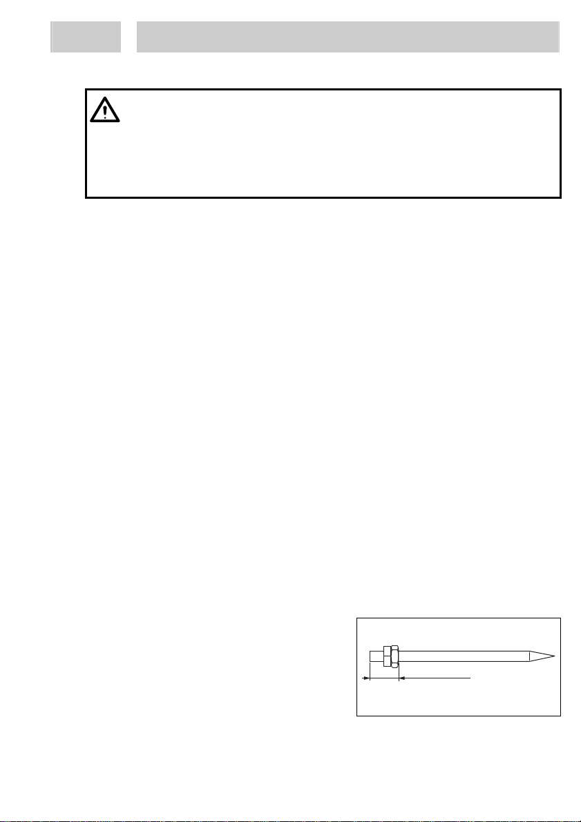
Needle nuts 8must be counter-screwed in such a position where “pre-“ and
“purging-air” work.
The correct position of needle nuts 8
on needle or extension needle is
8.8 – 9.0 mm from the end of the
needle and both nuts are countered
against each other firmly.
That applies also if extensions are
built-in additionally.
8.8 - 9.0 mm
.346" - .354"

10
6 Troubleshooting
Type of malfunction Possible causes Correction
Drops form on the trigger – The needle gasket 5is
worn respectively loose
and must slightly be
retightened.
•For that purpose
remove needle/valve
cartridge, see
section 4.3. Then
unscrew screw at the
valve body 4and take
out needle driver
(squared bolt). Using a
small screw driver turn
stuffing box 6gently
clockwise and try if
needle is sliding
smoothly again within
the tightened gasket.
Drops form on the nozzle – Either needle or nozzle
is worn.
– Needle is not closed
properly e.g. because
of particle residues
within nozzle.
•Replace needle or
nozzle.
•Clean the needle/valve
cartridge with solvent,
see section 5.
There is an uneven and
not steady spray jet – Dirt residue within air
cap.
– Nozzle is not correctly
screwed in.
•Clean air cap with
solvent.
•Make sure that nozzle
is screwed in tight.
Air blowing constantly
although trigger is
released.
– O-ring 9and/or
washer 10 worn.
– Needle nuts are not
counter-screwed in
correct position, see
section 5.3.
•Change O-ring and/or
washer.
Drops form on the
extension at the applicator
and/or the spray head.
– O-rings are worn. •Change O-rings, see
section 7.2.

11
7 Annex
7.1 Spare Parts Finespray Applicator 97715/97725
For the table below see illustration on page 6.
Pos. No. Description Loctite Order No.
97715
1, 2, 3 Nozzle Change Set 0.5 mm Nozzle, 90°
Air Cap, Protection Ring 8991507
97725
1, 2, 3 Nozzle Change Set HVLP 0.5 mm
Nozzle, 60° Air Cap, Protection Ring 8991517
For both
– Sealing and Repair Kit for 97715/97725
consists of 97730
7.2 Spare Parts Extensions
Pos. No. Description
1 O ring 3*1 mm, Viton
2 O ring 10.82*1.78 mm, Viton
1
2

12
7 Annex
7.3 Accessories
Description Loctite Order No.
97715
Finespray Applicator 0.5 mm nozzle, 90° spray head,
90° flat fan, with Extension length of 200 mm. 97726
Finespray Applicator 0.5 mm nozzle, 90° spray head,
90° flat fan, with Extension length of 400 mm. 97727
Finespray Applicator 0.5 mm nozzle, 90° spray head,
90° flat fan, with Extension length of 600 mm. 97728
Finespray Applicator 0.5 mm nozzle, 45° spray head,
90° flat fan, with Extension length of 600 mm. 97729
Nozzle Change Set 0.3 mm nozzle, 90° air cap, and
protection ring. 8991516
Nozzle Change Set 0.5 mm nozzle, 90° air cap, and
protection ring. 8991517
Nozzle Change Set 0.8 mm nozzle, 90° air cap, and
protection ring. (Not for the use with extensions). 8991518
97725
Finespray Applicator 0.5 mm nozzle, 90° spray head,
60° flat fan, with Extension length of 200 mm. 97716
Finespray Applicator 0.5 mm nozzle, 90° spray head,
60° flat fan, with Extension length of 400 mm. 97717
Finespray Applicator 0.5 mm nozzle, 90° spray head,
60° flat fan, with Extension length of 600 mm. 97719
Finespray Applicator 0.5 mm nozzle, 45° spray head,
60° flat fan, with Extension length of 600 mm. 97720
For the use with extensions:
Nozzle Change Set 0.3 mm nozzle, 60° air cap, and
protection ring. 8991521
Nozzle Change Set 0.5 mm nozzle, 60° air cap, and
protection ring. 8991522
Spray Guns with
90° Extensions
Spray Guns with
45° Extensions

13
7 Annex
Description Loctite Order No.
For the use only with applicator 97725:
Nozzle Change Set HVLP 0.3 mm nozzle, 60° air cap,
and protection ring. 8991506
Nozzle Change Set HVLP 0.5 mm nozzle, 60° air cap,
and protection ring. 8991507
Nozzle Change Set HVLP 0.8 mm nozzle, 60° air cap,
and protection ring. 8991508
For both
Finespray Applicator 0.5 mm nozzle, 15° ring fan, with
Extension length of 600 mm 97721
Separator with sinter filter and drain valve 97714
There are extensions in graduated lengths of 100 mm, maximum 600 mm, on
request.
Nozzle change sets in sizes of 1.0 mm 1.2 mm and 1.5 mm with different air caps of
90° flat fan; 45° flat fan and 15° ring spray are available on request.
The sizes of the air caps of 90° flat fan, 45° flat fan and 15° ring spray applies
also to the nozzle change sets 8991506, 8991507 and 8991508 and are available
on request.

14
Inhaltsverzeichnis
Deutsch
1 Bitte beachten Sie................................................................................. 15
1.1 Hervorhebungen ..................................................................................... 15
1.2 Lieferumfang........................................................................................... 15
1.3 Einsatzbereich (Bestimmungsgemäße Verwendung) ............................. 15
1.4 Zu Ihrer Sicherheit .................................................................................. 16
2 Gerätebeschreibung............................................................................. 18
3 Technische Daten ................................................................................. 19
4 Einstellung und Inbetriebnahme ......................................................... 19
4.1 Einstellung .............................................................................................. 19
4.2 Inbetriebnahme....................................................................................... 20
4.3 Außerbetriebnahme ................................................................................ 20
4.4 Erneute Inbetriebnahme ......................................................................... 20
5 Pflege und Wartung.............................................................................. 21
5.1 Pflege...................................................................................................... 21
5.2 Wechseln der Düse................................................................................. 21
5.3 Demontieren der Ventilnadel................................................................... 21
6 Beseitigen von Störungen.................................................................... 22
7 Anhang................................................................................................... 23
7.1 Ersatzteile Feinsprühpistole 97715/97725 .............................................. 23
7.2 Ersatzteile Verlängerungen..................................................................... 23
7.3 Zubehör .................................................................................................. 24

15
1 Bitte beachten Sie
1.1 Hervorhebungen
Gefahr!
Verweist auf Sicherheitsvorschriften und fordert Vorsichtsmaßnahmen, die den
Betreiber des Gerätes oder andere Personen vor Verletzungs- oder Lebensgefahr
schützen.
Achtung!
Hebt hervor, was getan oder unterlassen werden muss, um das Gerät oder andere
Sachwerte nicht zu beschädigen.
Bedingt durch die technische Entwicklung können die Abbildungen und
Beschreibungen in dieser Bedienungsanleitung vom tatsächlich ausgelieferten
Gerät in Details abweichen.
Die fett gedruckten Zahlen im Text beziehen sich auf die entsprechende
Positionsnummer in der Abbildung auf Seite 18.
•Der Punkt hebt einen Handlungsschritt hervor.
1.2 Lieferumfang
1 Feinsprühpistole 97715 oder 1 Feinsprühpistole HVLP 97725
1 Duo-Schlauch, montiert,
1 Bedienungsanleitung oder
1 Feinsprühpistole mit Verlängerung
1 Duo-Schlauch, montiert,
1 Bedienungsanleitung
1.3 Einsatzbereich (Bestimmungsgemäße Verwendung)
Die Feinsprühpistolen 97715 und 97725 sind Hochleistungs-Sprühgeräte und
Präzisionswerkzeuge. Sie werden für die Feinstdosierung von niedrigviskosen
Loctite®Frekote®Produkten eingesetzt. Im Unterschied zum Gerät 97715 ist das
Modell 97725 eine HVLP-Spritzpistole (HVLP = High Volume Low Pressure, großes
Volumen bei niedrigem Druck). Die HVLP-Sprühpistole 97725 arbeitet mit einem
niedrigeren Eingangs- und Düseninnendruck und größerem Luftvolumen. Der
Spritzstrahl ist erheblich feiner, und es wird weniger Sprühnebel erzeugt.
Modell 97715 hat eine 90°-Flachstrahl-Luftkappe, 97725 eine 60°-Flachstrahl-
Luftkappe.
Die Pistole eignet sich nicht zum Versprühen von aggressiven Medien wie Säuren,
alkalischen Lösungen, Reinigern (chlorierte Kohlenwasserstoffen) oder
Chemikalien.
Gerät immer sauber halten und die wichtigsten Hinweise beachten, um lange
Lebensdauer der Pistole zu gewährleisten.

16
1 Bitte beachten Sie
Je nach Viskosität des flüssigen Mediums stehen die folgenden Düsendurchmesser
zur Verfügung:
∅0,3 und ∅0,8 mm (Luftkappe wird nur in einer Größe benötigt).
– Die Standardausführung der Feinsprühpistole 97715 hat einen
Düsendurchmesser von 0,5 mm und eine Flachstrahl-Luftkappe mit ca. 90°
Sprühwinkel.
– Die Standardausführung der Feinsprühpistole HVLP 97725 hat einen
Düsendurchmesser von 0,5 mm und eine Flachstrahl-Luftkappe mit ca. 60°
Sprühwinkel.
Wenn ein Rundstrahl erzielt werden soll, einfach die Luftkappe durch eine
Rundstrahl-Luftkappe ersetzen.
Die Flachstrahl-Luftkappe kann für einen Sprühstrahl in horizontaler, vertikaler oder
in irgendeiner dazwischen liegenden Position eingestellt werden.
Wenn Sie spezielle Luftkappen mit anderen Sprühwinkeln benötigen, wenden Sie
sich bitte an Ihre Henkel Loctite Vertretung.
1.4 Zu Ihrer Sicherheit
Für den gefahrlosen und erfolgreichen Einsatz des Gerätes diese Anleitung
vollständig lesen. Der Hersteller kann nicht für Schäden verantwortlich gemacht
werden, die infolge der Nutzung abweichend vom bestimmungsgemäßen Gebrauch
oder der Nichtbeachtung von Sicherheitshinweisen oder Warnungen, verursacht
werden.
Bewahren Sie diese Anleitung nach Durchsicht griffbereit auf.
Technisches Datenblatt und Sicherheitsdatenblatt (gem. EU Richtlinie 91/155/EU)
für das eingesetzte LOCTITE®Frekote® -Produkt anfordern bei
Henkel Loctite Deutschland GmbH
www.loctite.com für die nordamerikanische Version des Datenblattes;
+49 89 92 68 11 67 für die englische Version des Datenblattes;
089-92 68 11 22 für die deutsche Version des Datenblattes.
ANWEISUNGEN IN DIESEN DATENBLÄTTERN UNBEDINGT BEFOLGEN!
Unbedingt zu befolgende Verarbeitungshinweise
1 Bei unzureichender Belüftung
Atemschutz tragen!
2 Undurchlässige und
lösemittelbeständige
Schutzkleidung und Schürze
tragen!
3 Dichtschließende Schutzbrille
tragen!
4 Schutzhandschuhe tragen!
5 Nicht rauchen!
12
35
4

17
1 Bitte beachten Sie
Vorliegende Bedienungsanleitung vor Benutzung des Gerätes sorgfältig lesen.
Nichtbeachtung der Anweisungen in der Bedienungsanleitung könnte zu
Verletzungen oder Schäden am Gerät führen.
Wenn chemische Produkte nicht ordnungsgemäß gehandhabt werden, kann dies zu
Gesundheitsschäden führen!
Allgemeine Sicherheitsvorschriften für den Umgang mit Chemikalien beachten!
Anweisungen des Herstellers beachten!
Keine Lösungsmittel, Reinigungsflüssigkeiten oder Beschichtungsmaterialien
verwenden, die 1,1,1 Trichlorethan oder Methylenchlorid, d.h. Stoffe aus der
Gruppe der chlorierten Kohlenwasserstoffe, enthalten. Diese chemischen Stoffe
können mit Aluminium-, eloxierten oder verzinkten Teilen reagieren. Die chemische
Reaktion kann explosiv verlaufen.
Gefahr beim Versprühen von brennbaren und gesundheitsschädlichen Stoffen.
Sicherheitshinweise auf dem Materialgebinde und im Datenblatt des
Materialherstellers unbedingt beachten.
Sprühpistole niemals auf Personen richten.
Beim Sprühen können abhängig vom eingestellten Druck Geräusche auftreten.
Ggf. wird das Tragen von Gehörschutz empfohlen.
Ungeschützte Personen fernhalten.
Verschütten oder Versprühen in geschlossenen Räumen vermeiden.
Nur in gut gelüfteten Bereichen verwenden.
Für gute Raumbelüftung auch im Bodenbereich sorgen (Dämpfe sind schwerer
als Luft).
Für geeignete Absaugung an den Verarbeitungsmaschinen sorgen.
Vor Hitze und direkter Sonnenbestrahlung schützen.
Nicht gegen Flammen oder auf glühende Körper sprühen.
Von Zündquellen fernhalten.
Reizt die Augen, die Atmungsorgane und die Haut.
Bei Berührung mit den Augen sofort gründlich mit Wasser abspülen und Arzt
konsultieren, siehe Sicherheitsdatenblatt des eingesetzten Produktes.

18
2 Gerätebeschreibung
Die Feinsprühpistolen 97715 und 97725 wurden von Loctite vor Verlassen des
Werkes gründlich getestet. Weitere Einstellungen sind vor Beginn der
Sprüharbeiten nicht erforderlich.
1 Überwurfring
2 Luftkappe bei 97715 (90° Flachstrahl) und 97725 HVLP (60° Flachstrahl).
3 Düse, Standardgröße 0,5 mm in Edelstahl.
4 Pistolenkörper mit Abzugshebel, Luft- und Materialanschlüssen.
5 Nadeldichtung (PTFE).
6 Stopfbuchse
7 Nadel, Edelstahl.
8 Nadelmuttern, M2.
9 O-Ring 4,7 * 1,42 mm.
10 Ventildichtung
11 Ventilfeder
12 Nadelfeder
13 Ventilkegelstück
14 Anschlagschraube
15 Nadel-Regler mit Kontermutter
16 Druckluftanschluss “AIR” für Schlauch, blau, AD 6 mm, ID 4 mm.
17 Materialanschluss “M” für Schlauch, klar, AD 6 mm, ID 4 mm.
1234
5678910 1112 1314
M
M
AIR
15
1617

19
3 Technische Daten
Qualität: Wenn die
erforderliche Qualität nicht
erreicht wird, ist ein LOCTITE-
Abscheider zu installieren
Gefiltert 10 µm, ölfrei, nicht kondensierend
Zubehör - Artikelnr. 97714
Max. Luftdruck 6 bar
Max. Materialdruck 1,5 bar,
siehe Bedienungsanleitung des Druckbehälters
Luftverbrauch Ca. 90 l/min bei 3 bar und 0,5 mm Düse
Gewicht 0,240 kg
Länge, Duo-Schlauch ~ 3 m
4 Einstellung und Inbetriebnahme
Sicherheitshinweise in Abschnitt 1.4 "Für Ihre Sicherheit" beachten.
4.1 Einstellung
Falls die Materialmenge individuell eingestellt werden muss, den Nadel-Regler mit
Kontermutter 15 zur Mengenregulierung verwenden. Zum Versprühen mit einer
Sprühpistole ist ein definiertes Volumen an Zerstäubungsluft und ein definierter
Materialdruck erforderlich. Durch Betätigung des Abzugs wird die Nadel geöffnet,
und das Material tritt an der Düse aus. Der Luftdruck zerstäubt das Material und
formt es zu einem Strahl.
Die Nadelfunktion ist wie folgt: Öffnen durch Betätigung des Abzugs, Schließen
durch Federdruck.
•Duo-Schlauch an Druckbehälter oder andere Materialversorgung und an
Druckluftversorgung anschließen.
Klarer Schlauch: für Material, Anschluss M 17.
Blauer Schlauch: für Druckluft, Anschluss AIR 16.
•Druckluft mit Hilfe des Reglers am Druckbehälter auf die erforderliche
Tröpfchengröße einstellen, siehe Bedienungsanleitung für den Druckbehälter.
•Materialdruck mit Hilfe des Materialreglers am Druckbehälter auf die erforderliche
Materialmenge und Tröpfchengröße einstellen, siehe Bedienungsanleitung für
den Druckbehälter.

20
4 Einstellung und Inbetriebnahme
4.2 Inbetriebnahme
Die Materialmenge kann individuell eingestellt werden. Zur Mengenregulierung den
Nadel-Regler mit Kontermutter 15 verwenden.
Nadel-Regler nach rechts drehen: Materialfluss wird verringert.
Nadel-Regler nach links drehen: Materialfluss wird vergrößert.
•Abzugshebel am Pistolenkörper 4betätigen. Der Sprühvorgang beginnt.
Sie werden bemerken, dass Sie beim Betätigen des Abzugs zuerst die sogenannte
"Vorluft" bekommen, dann erst fließt das Spritzmedium. Beim Entlasten des Hebels
folgt noch die Entlüftung, während die Nadel schon die Düse geschlossen hat und
der Materialfluss unterbrochen ist. Dadurch wird verhindert, dass die Flüssigkeit
Tropfen bildet, anstatt die gewünschte Zerstäubung zu erzeugen.
4.3 Außerbetriebnahme
•Feinsprühpistole nach oben halten.
•Druckbehälter entlüften.
Das Spritzmedium fließt in den Druckbehälter zurück.
4.4 Erneute Inbetriebnahme
•Druckbehälter belüften.
•Abzugshebel am Pistolenkörper 4betätigen. Der Sprühvorgang beginnt.
Produktschlauch wird gefüllt.
This manual suits for next models
1
Table of contents
Languages:
Other Loctite Paint Sprayer manuals


