LoLo LKT-45G User manual

PART NUMBER 156679 Rev. B (08/13)
THIS MANUAL MUST BE RETAINED FOR FUTURE REFERENCE.
READ, UNDERSTAND AND FOLLOW THE INSTRUCTIONS AND
WARNINGS CONTAINED IN THIS MANUAL.
FOR YOUR SAFETY
Do not store or use gasoline or other ammable vapors
and liquids in the vicinity of this or any other appliance.
POST IN A PROMINENT LOCATION
Instructions to be followed in the event user smells gas.
This information shall be obtained by consulting your
local gas supplier. As a minimum, turn o the gas and
call your gas company and your authorized service agent.
Evacuate all personnel from the area.
WARNING
Improper installation, adjustment, alteration, service or
maintenance can cause property damage, injury or
death. Read the installation, operating and maintenance
instructions thoroughly before installing or servicing this
equipment.
NOTIFY CARRIER OF DAMAGE AT ONCE
It is the responsibility of the consignee to inspect the container upon receipt and
to determine the possibility of any damage, including concealed damage. LoLo
Commercial Foodservice Equipment suggests that if you are suspicious of dam-
age to make a notation on the delivery receipt. It will be the responsibility of the
consignee to le a claim with the carrier. We recommend that you do so at once.
Manufacturer’s Service/Questions 877-246-5656
Information contained in this document is known to be current and accurate at the time of
printing/creation. LoLo Commercial Foodservice Equipment recommends referencing our product
line website, www.getLoLo.com, for current product information and specifications.
This manual provides information for:
OPERATOR MANUAL
IMPORTANT INFORMATION, KEEP FOR OPERATOR
MODEL: LKT-45G
Steam Jacketed Kettle

2 OM-LKT-45G
IMPORTANT - READ FIRST - IMPORTANT
IMPORTANT
: BE SURE OPERATORS READ, UNDERSTAND AND FOLLOW THE OPERATING INSTRUCTIONS,
CAUTIONS, AND SAFETY INSTRUCTIONS IN THIS MANUAL.
WARNING: THIS UNIT IS INTENDED FOR USE IN THE COMMERCIAL HEATING, COOKING AND HOLDING OF
WATER AND FOOD PRODUCTS, PER THE INSTRUCTIONS CONTAINED IN THIS MANUAL. ANY OTHER
USE COULD RESULT IN SERIOUS PERSONAL INJURY OR DAMAGE TO EQUIPMENT AND WILL
VOID WARRANTY.
WARNING: KETTLE MUST BE INSTALLED BY PERSONNEL QUALIFIED TO WORK WITH ELECTRICITY. IMPROPER
INSTALLATION CAN RESULT IN INJURY TO PERSONNEL AND/OR DAMAGE TO EQUIPMENT.
WARNING: ELECTRICALLY GROUND THE UNIT AT THE TERMINAL PROVIDED. FAILURE TO GROUND UNIT
COULD RESULT IN ELECTROCUTION AND DEATH.
CAUTION: DO NOT CONNECT ANY PIPING TO THE POP SAFETY VALVE. THE VALVE MUST BE FREE TO VENT
STEAM AS NEEDED. THE ELBOW ATTACHED TO THE SAFETY VALVE SHOULD POINT TO THE FLOOR.
IMPROPER INSTALLATION WILL VOID WARRANTY.
CAUTION: AVOID ALL DIRECT CONTACT WITH HOT EQUIPMENT SURFACES. DIRECT SKIN CONTACT COULD
RESULT IN SEVERE BURNS.
CAUTION: AVOID ALL DIRECT CONTACT WITH HOT FOOD OR WATER IN THE KETTLE. DIRECT CONTACT
COULD RESULT IN SEVERE BURNS.
CAUTION: DO NOT OVER FILL THE KETTLE WHEN COOKING, HOLDING OR CLEANING. KEEP LIQUIDS A
MINIMUM OF 2-3” (5-8 CM) BELOW THE KETTLE BODY RIM TO ALLOW CLEARANCE FOR STIRRING,
BOILING AND SAFE PRODUCT TRANSFER.
CAUTION: TAKE SPECIAL CARE TO AVOID CONTACT WITH HOT KETTLE BODY OR HOT PRODUCT WHEN
ADDING INGREDIENTS, STIRRING OR TRANSFERRING PRODUCT TO ANOTHER CONTAINER.
CAUTION: WHEN TILTING KETTLE FOR PRODUCT TRANSFER:
1) USE CONTAINER DEEP ENOUGH TO CONTAIN AND MINIMIZE SPLASHING.
2) PLACE CONTAINER ON STABLE, FLAT SURFACE, AS CLOSE TO KETTLE AS POSSIBLE.
3) DO NOT OVER FILL CONTAINER. AVOID DIRECT SKIN CONTACT WITH HOT CONTAINER AND
ITS CONTENTS.
CAUTION: KEEP FLOORS IN FRONT OF KETTLE WORK AREA CLEAN AND DRY. IF SPILLS OCCUR, CLEAN
IMMEDIATELY, TO AVOID SLIPS OR FALLS.
WARNING: FAILURE TO CHECK PRESSURE RELIEF VALVE OPERATION PERIODICALLY COULD RESULT IN
PERSONAL INJURY AND/OR DAMAGE TO EQUIPMENT.
CAUTION: WHEN TESTING, AVOID ANY EXPOSURE TO THE STEAM BLOWING OUT OF THE PRESSURE RELIEF
VALVE. DIRECT CONTACT COULD RESULT IN SEVERE BURNS.
WARNING: BEFORE REPLACING ANY PARTS, DISCONNECT THE UNIT FROM THE ELECTRIC POWER SUPPLY
AND CLOSE THE MAIN GAS VALVE. ALLOW FIVE MINUTES FOR UNBURNED GAS TO VENT.
WARNING: KEEP WATER AND SOLUTIONS OUT OF CONTROLS AND ELECTRICAL EQUIPMENT. NEVER USE A
HIGH PRESSURE HOSE TO CLEAN KETTLE SURFACES.
CAUTION: MOST CLEANERS ARE HARMFUL TO THE SKIN, EYES, MUCOUS MEMBRANES AND CLOTHING.
PRECAUTIONS SHOULD BE TAKEN. WEAR RUBBER GLOVES, GOGGLES OR FACE SHIELD AND
PROTECTIVE CLOTHING. CAREFULLY READ THE WARNINGS AND FOLLOW THE DIRECTIONS ON
THE LABEL OF THE CLEANER TO BE USED.

OM-LKT-45G 3
CAUTION: USE OF ANY REPLACEMENT PARTS OTHER THAN THOSE SUPPLIED BY LOLO COMMERCIAL
FOODSERVICE EQUIPMENT OR THEIR AUTHORIZED DISTRIBUTORS CAN CAUSE OPERATOR
INJURY AND DAMAGE TO THE EQUIPMENT, AND WILL VOID ALL WARRANTIES.
IMPORTANT
: SERVICE PERFORMED BY OTHER THAN FACTORY AUTHORIZED PERSONNEL WILL VOID
WARRANTIES.
IMPORTANT - READ FIRST - IMPORTANT
IMPORTANT FOR FUTURE REFERENCE
Please record this information and retain this manual for the life of the equipment. For Warranty Service
and/or parts, this information is required.
SAFETY PRECAUTIONS
Before installing and operating this equipment be sure everyone involved in its
operation are fully trained and are aware of all precautions. Accidents and problems
can result from a failure to follow fundamental procedures and precautions.
The following words and symbols, found in this manual, alert you to potential hazards
to the operator, service personnel or the equipment. The words are defined as follows:
DANGER: This symbol warns of an imminent hazard which will result in serious
injury or death.
WARNING: This symbol refers to a potential hazard or unsafe practice, which could
result in serious injury or death.
CAUTION: This symbol refers to a potential hazard or unsafe practice, which could
result in minor or moderate injury, or product or property damage.
NOTICE: This symbol refers to information that needs special attention or must be
fully understood even though not dangerous.
TO AVOID PROPERTY DAMAGE, PERSONAL INJURY OR DEATH,
SHUT OFF GAS BEFORE SERVICING THE UNIT.
TO AVOID PROPERTY DAMAGE, PERSONAL INJURY OR DEATH,
CHECK ALL JOINTS IN THE GAS SUPPLY LINE FOR LEAKS PRIOR
TO LIGHTING. USE SOAP AND WATER SOLUTION (BUBBLES). DO
NOT USE AN OPEN FLAME.
A. CHECK ALL JOINTS IN FRONT OF (BEFORE) THE GAS VALVE
BEFORE LIGHTING UNIT.
B. CHECK ALL JOINTS BEYOND THE GAS VALVE AFTER THE
UNIT IS LIT.
TO AVOID PROPERTY DAMAGE, PERSONAL INJURY OR DEATH,
ALL GAS JOINTS DISTURBED DURING SERVICING MUST BE
CHECKED FOR LEAKS. CHECK WITH A SOAP AND WATER
SOLUTION (BUBBLES). DO NOT USE AN OPEN FLAME.
This product is intended for commercial use only. Not for household use.
Local codes regarding installation vary greatly from one area to another.
The National Fire Protection Association, Inc., states in its NFPA96 latest edition that
local codes are “Authority Having Jurisdiction” when it comes to requirements for
installation of equipment. Therefore, installation should comply with all local codes.
Model Number Serial Number Date Purchased

4 OM-LKT-45G
Important Warnings & Safety Precautions ........................................... 2-3
References.............................................................................................. 4
Equipment Description........................................................................... 5
Inspect for Shipping Damage .................................................................. 6
Uncrating ................................................................................................ 6
Installation Instructions ....................................................................... 7-8
Initial Start-Up........................................................................................ 9
Operation – General Kettle Use ...................................................... 10-12
Cleaning .......................................................................................... 13-14
Maintenance .................................................................................... 14-16
Troubleshooting Guide .................................................................... 17-18
Parts Lists & Diagrams .................................................................... 19-24
Electrical Schematic ............................................................................. 25
NATIONAL FIRE PROTECTION ASSOCIATION
60 Batterymarch Park
Quincy, Massachusetts 02269
NFPA/70
The National Electrical Code
NFPA/54
The National Fuel Gas Code
NSF INTERNATIONAL
789 N. Dixboro Rd.
Ann Arbor, Michigan 48113-0140
INTERTEK (ETL)
1950 Evergreen Blvd, Suite 100
Duluth, GA 30096
AMERICAN NATIONAL STANDARDS INST., INC.
1430 Broadway
New York, New York 10018
Z223.1-1984 - National Fuel Gas Code
Z21.30 - Installation Gas Appliances & Piping
Table of Contents
References

OM-LKT-45G 5
Congratulations on your purchase of LoLo commercial cooking
equipment. LoLo takes pride in the design and quality of our products.
When used as intended and with proper care and maintenance, you will
experience years of reliable operation from this equipment. To ensure
best results, it is important that you read and follow the instructions in
this manual carefully.
The LoLo LKT-45G is a floor-mounted, tilting steam-jacketed kettle with a
thermostatically controlled, self-contained, gas-heated steam supply and
appropriate controls, mounted on a sturdy stand. The self-contained steam source is
heated by natural gas or propane. Burner ignition is automatic and electronic.
The kettle body is constructed of stainless steel, welded into one solid piece and
sheathed in stainless steel with an insulating air gap. The kettle is furnished with a
wide rim and a butterfly shaped pouring lip. The steam jacket is ASME shop inspected
and registered with the national board for working pressures up to 25 PSI.
The kettle is tilted with a hand crank to pour out its contents. Stainless steel panels
enclose the controls. Four stainless steel tubular legs support the unit. Bullet or
(optional) flanged feet on each of the legs can be adjusted to level the kettle.
The kettle is charged at the factory with chemically pure water which contains rust
inhibitors. The steam source provides a temperature range of 150º to approximately
267ºF (65 to 131ºC). Unit controls include a thermostat, pressure gauge, safety valve,
pressure limit control, low water cut-off, power switch and gas regulator valve. The
gas supply shuts off automatically when the kettle is tilted.
The unit must be specified for use with natural or propane gas. Service connections
for gas and electricity are required. Standard electric power supply is 120/1/60.
Optional equipment includes:
• Flanged feet
• Kettle brush kit
• Lift-off cover with built-in strainer
KEY UNIT DIMENSIONS
Dimension US/Metric Performance Characteristics
Unit Width 45.2” 1148 mm Max. PSI 25
Rim Height 43.7” 1110 mm Temp. Range 150 to 265° F
Unit Depth 42.1” 1069 mm Rim Capacity 45 gal. 170 l
Ship. Weight 725 lbs 329 kg Working Cap. 36 gal. 136 l
POWER REQUIREMENTS
Electric Service Gas Service (via ½” NPT Fitting )
Voltage 120 TYPE NATURAL PROPANE
Phase 1 Firing Rate 96,000 BTU/hr 96,000 BTU/hr
Hz 60 Min. Pressure 4.5” W.C. 4.5” W.C.
Amp Load 5 Max. Pressure 11” W.C. 11” W.C.
Equipment Description

6 OM-LKT-45G
Inspect for Shipping Damage
All containers should be examined for damage before and during unloading. The
freight carrier has assumed responsibility for its safe transit and delivery. If the
equipment is received damaged, either apparent or concealed, a claim must be made
with the delivering carrier.
1. Apparent damage or loss must be noted on the freight bill at the time of
delivery. It must then be signed by the carrier representative (driver). If this is
not done, the carrier may reject the claim. The carrier can supply the necessary
claim forms.
2. Concealed damage or loss if not apparent until after the equipment is uncrated,
can also be claimed. However, a request for inspection must be made to the
carrier within 15 days. The carrier should arrange an inspection. Be certain to
retain all contents and packaging material.
USE CAUTION WHEN UNCRATING LOLO
EQUIPMENT. METAL AND PLASTIC BANDING
IS UNDER TENSION AND CAN SNAP BACK
WHEN CUT. WOOD PALLETS OR SKIDS CAN
CONTAIN SPLINTERS AND NAILS. SHIPPING
CARTONS CAN CONTAIN LARGE STAPLES.
WEAR GLOVES AND PROTECTIVE EYEWEAR
WHEN OPENING, MOVING AND DISPOSING
OF SHIPPING CONTAINERS.
Uncrating
1. Cut strapping or banding that closes the top of the cardboard shipping carton
and secures it to the wood pallet.
2. Lift carton straight up and off the kettle. Obtain help, if needed.
3. Remove any Styrofoam blocking or wood bracing that protects unit from ship-
ping damage.
4. Cut strapping or banding that secures kettle to the wood pallet or skid.
5. This kettle weighs over 700 pounds (320 kg). Use material handling equipment
(forklift, pallet jacket, etc.) to lift the kettle off and clear of wood pallet.
IMPORTANT: Use caution to avoid damage to kettle jacket sheathing, jacket fill
assembly or burner assembly parts underneath the kettle, during the lift and
movement. Lift the kettle using the horizontal cross-braces on the trunnion
support legs.
6. Pull off any grey/white plastic from stainless steel surfaces. This adhesive-
backed plastic protects surfaces for scratches during fabrication and shipping.
7. Dispose of cardboard carton, Styrofoam and wood pallet/skid by recycling.
THIS UNIT IS VERY HEAVY. INSTALLER SHOULD
OBTAIN HELP OR USE MATERIALS HANDLING
EQUIPMENT AS NEEDED TO LIFT THIS WEIGHT
SAFELY.

OM-LKT-45G 7
GENERAL INSTALLATION – CODE REQUIREMENTS
Install the gas appliance in a well ventilated area. Adequate air must be supplied
to replenish the air used for combustion. Ventilation must employ a vent hood and
exhaust fan with no direct connection between the vent duct and the kettle flue.
Installation must conform with local codes and/or with the National Fuel Gas Code,
ANSI Z223.1/NFPA-54 (latest edition) or the Natural Gas and Propane Installation
Code CSA B149.1 as applicable. NOTE: Local codes may require that the kettle be
electrically interlocked to shut off the gas supply and prevent the operation of the unit
if the exhaust fan is not operation or if the fire suppression system is activated. Failure
to follow these instructions can cause bodily injury and/or property damage.
SITE SELECTION & REQUIREMENTS
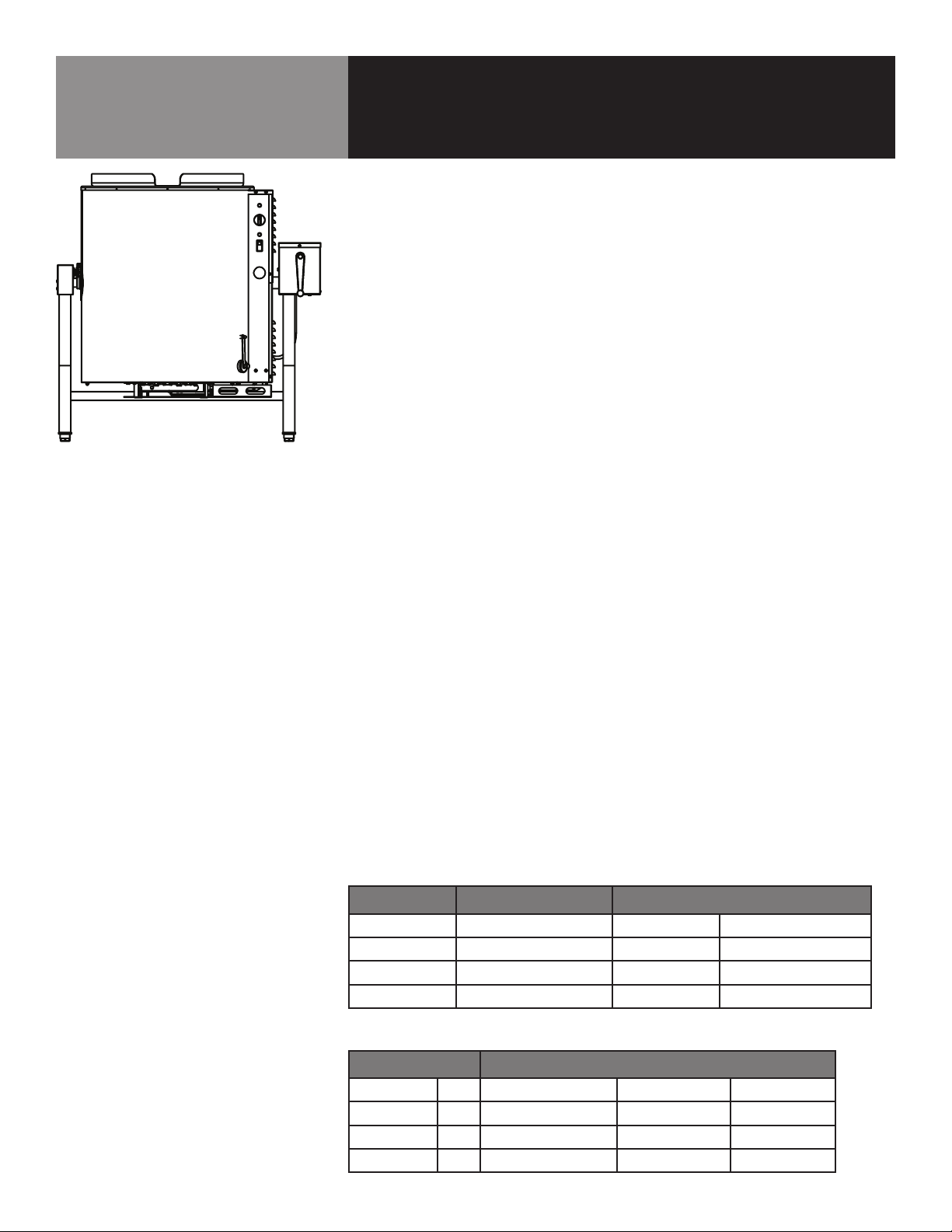
The LoLo gas-heated floor-model tilting steam jacketed kettle must be:
1. Installed in a commercial kitchen with ready access to natural or propane gas,
plus 120 volt, single phase 60 cycle electric power;
2. Positioned under a Type I commercial ventilation hood capable of full capture of
gas combustion byproducts, heat, grease and water vapor produced during the
operation and use (cooking) of the kettle;
3. Provided with a level, sturdy, stable floor capable of supporting the weight of the
kettle (725 lbs/283 kg) plus up to 36 gallons/136 liters of product, which can
weigh over 300 pounds/140 kg.
4. Provided with enough space to ensure easy cleaning and minimum clearances
from non-combustible surfaces of:
• 2” (51 mm) on both sides
• 6” (152 mm) in rear from gas flue
KETTLE POSITIONING & COMPONENT ASSEMBLY
1. Position & Level the Kettle:
• Obtain sufficient help or use material handling equipment to lift the kettle
and position it on a floor area that meets the load support criteria described
above. TIP: If possible, locate the kettle where a floor sink or drain is
available and positioned directly under the kettle pouring lip. (See LoLo
LKT-45G Specification Sheet 159750 for pour path dimensions.)
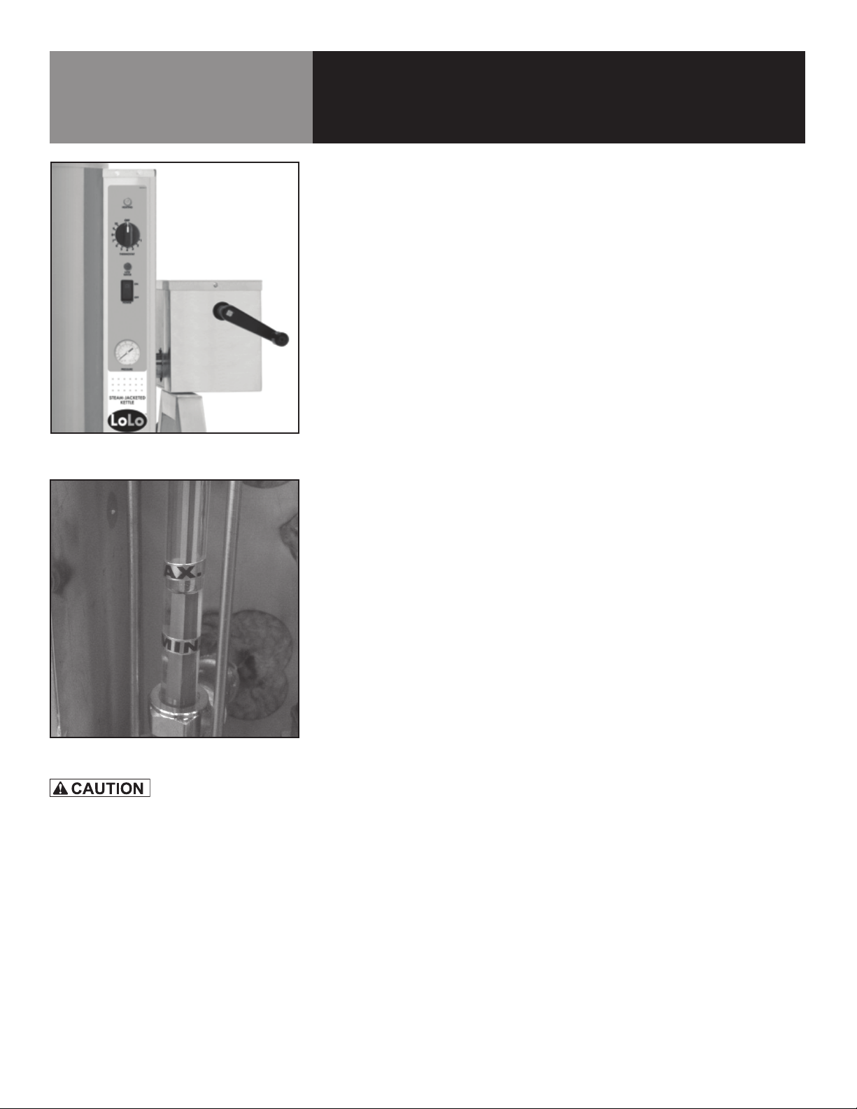
• Verify that the kettle body is in the full-upright position. The crank tilt will
stop when it is vertical. Use a spirit level to check the level of the kettle
from left-to-right and front-to-back. Lay the level on the top rim to check
level.
• If the kettle is not level, rotate one or two of the three height-adjustable
Installation Instructions
INSTALLER MUST VERIFY THAT THE
INSTALLATION COMPLIES WITH THE
APPLICABLE LOCAL CODES AND
REGULATIONS. THE UNIT MUST BE
INSTALLED BY A LICENSED PLUMBER OR
GAS FITTER WHEN INSTALLED WITHIN THE
COMMONWEALTH OF MASSACHUSETTS.
INSTALLATION OF THE KETTLE MUST BE DONE
BY A LICENSED PLUMBER OR AUTHORIZED
REPRESENTATIVE QUALIFIED TO WORK WITH
GAS. IMPROPER INSTALLATION CAN RESULT
IN INJURY TO PERSONNEL AN/OR DAMAGE TO
EQUIPMENT.
THE AREA DIRECTLY AROUND THE APPLIANCE
MUST BE CLEARED OF ALL COMBUSTIBLE
MATERIAL. FAILURE TO FOLLOW THESE
INSTRUCTIONS CAN CAUSE BODILY INJURY
AND/OR PROPERTY DAMAGE.
INSTALLATION OF THE KETTLE MUST BE DONE
BY A CERTIFIED ELECTRICIAN OR AUTHORIZED
REPRESENTATIVE QUALIFIED TO WORK WITH
ELECTRICITY. IMPROPER INSTALLATION CAN
RESULT IN INJURY TO PERSONNEL AN/OR
DAMAGE TO EQUIPMENT.
DO NOT CONNECT ANY PIPING TO THE POP
SAFETY VALVE. THE VALVE MUST BE FREE
TO VENT STEAM AS NEEDED. IMPROPER
INSTALLATION WILL VOID THE WARRANTY!

8 OM-LKT-45G
feet on the kettle as needed and recheck level.
2. For OPTIONAL Flanged Feet:
• Obtain sufficient help or use material handling equipment to lift one side of
the kettle.
• Use a heavy screwdriver and hammer (or mallet) to tap the adjustable
bullet feet out of the frame support legs. They are a tight press fit.
• Position the optional flanged foot into the frame support leg and use the
hammer or mallet to seat the flanged foot. Don’t bend the floor flange
when seating the foot.
NOTE: Flanged feet are height adjustable and can be leveled by following
the Kettle Leveling Instructions on page 7. After the Kettle is positioned as
desired and leveled, the flanged feet can be secured with floor anchors,
per local codes and best practice.
MAKE ELECTRIC POWER CONNECTION
1. Provide 120 VAC, 60 Hz, 1 Ph, 3 Amp electrical service for standard unit. Use 1/2
inch waterproof conduit and waterproof connections. A cutout is provided in the
back of the control panel enclosure, just above the gas pipe nipple.
IMPORTANT: Observe local codes and/or The National Electrical Code in
accordance with ANSI/NFPA-70 latest edition. In Canada, provide electrical
service in accordance with the Canadian Electrical Code CSA C22.1 Part 1 and/
or local codes.
2. AN ELECTRICAL GROUND IS REQUIRED. The electrical schematic is located on
the inside of the service panel and on page 25 of this manual.
MAKE GAS CONNECTION
1. The internal gas lines of the unit were cleaned and closed off with a gas cock
before the unit was shipped from the factory. IMPORTANT: Free external gas
lines of lint, dirt, metal chips, sealant, grease, oil, and other contaminants before
you connect the lines to the kettle.
2. Connect the gas cock of the kettle to the gas service main with 1/2 inch IPS line
or approved equivalent.
IMPORTANT: Installation must conform with local codes or with the American
National Standard Z223, latest edition, National Fuel Gas Code. In Canada,
installation must conform to CAN/CGA B149 Installation Codes for Gas Appliance
and Equipment and/or local codes. Do NOT obstruct the flue or vent duct after
installation.
3. After the kettle has been connected to the gas supply, all gas line joints must be
checked for leaks. DO NOT USE A FLAME TO CHECK FOR LEAKS. A thick soap
solution or other suitable leak detector should be employed.
Installation Instructions
PRESSURE TEST WARNING
1. During pressure testing of the gas supply
piping system at pressure exceeding 0.5 PSIG,
the kettle and its individual shutoff valve must
be disconnected from the gas supply piping
system.
2. During pressure testing of the gas supply
piping system at pressures equal to or less
than 0.5 PSIG (3.45 kPa), the kettle must be
isolated from the gas supply piping system by
closing its individual manual shutoff valve.
ELECTRICALLY GROUND THE UNIT AT THE
TERMINAL PROVIDED. FAILURE TO GROUND
THE UNIT COULD RESULT IN ELECTROCUTION
AND DEATH.
DO NOT CONNECT ANY PIPING TO THE POP
SAFETY VALVE. THE VALVE MUST BE FREE
TO VENT STEAM AS NEEDED. IMPROPER
INSTALLATION WILL VOID THE WARRANTY!
THE ELBOW ATTACHED TO THE SAFETY
VALVE MUST POINT TO THE FLOOR.

OM-LKT-45G 9
Initial Start-Up
IMPORTANT
BE SURE ALL OPERATORS READ, UNDERSTAND
AND FOLLOW THE OPERATING INSTRUCTIONS,
CAUTIONS, AND SAFETY INSTRUCTIONS
CONTAINED IN THIS MANUAL.
AVOID ALL DIRECT CONTACT WITH HOT
SURFACES. DIRECT SKIN CONTACT COULD
RESULT IN SEVERE BURNS.
AVOID ALL DIRECT CONTACT WITH HOT
FOOD OR WATER IN THE KETTLE. DIRECT
CONTACT COULD RESULT IN SEVERE BURNS.
Now that the kettle has been installed, it should be tested to ensure that it is operating
correctly.
1. Remove any literature and packing materials from inside of the unit.
2. Confirm that the tilting mechanism is operating properly by tilting the kettle
through its full range. Then return the kettle to the upright position.
3. Turn on the electrical service to the unit.
4. Pour 1-2 quarts of water into the kettle.
5. Following “To Start Kettle” instructions in the “Operation” section (Page 10),
begin heating the water at the highest thermostat setting. The HEATING indicator
light should come on, and heating should continue until the water boils.
If the unit functions as described, it is ready for use. If it does not function as
described, contact your LoLo Authorized Service Agency.

10 OM-LKT-45G
Operation - General Kettle Use
OPERATOR CONTROLS
1. Manual gas valve. Controls the supply of gas from the main line to the kettle.
2. Power on/off switch. This switch turns the control circuit power on or off.
3. Thermostat dial. This turns the thermostat on or off, ignites the main burner to
create steam and sets the kettle operating temperature.
4. Hand wheel (crank). Used to tilt the kettle body.
5. Indicator lights, to alert operator of unit conditions:
a. Power indicator (green), shows that electric power is turned on.
b. HEATING indicator (amber), indicates that main gas is on to produce
steam in the kettle jacket.
c. LOW WATER indicator (red), warns that jacket water level is low.
TO START KETTLE
1. CHECK THE WATER LEVEL IN THE JACKET EVERY DAY. The level should be at the
middle of the sight glass, between MAX and MIN lines. (See Photo 10-2 at left). If
the level is low, see “Jacket Filling” in the “Maintenance” section of this manual.
2. While the kettle is cold, check the pressure gauge. If the gauge does not show
-20 to -30 inches of vacuum (that is, a reading below 0), see “Jacket Vacuum”
in the “Maintenance” section of this manual.
3. If closed, open main supply gas valve (handle in line with the pipe).
4. Turn the POWER switch to ON. For 90 seconds or until it succeeds,
the electronic ignition control will attempt to light the pilot. IMPORTANT: DO NOT
attempt to light any burner with a flame.
5. Once the pilot is lit, turn the thermostat dial to the desired setting.
6. If the pilot does not light, turn power OFF and wait five minutes. At
that time, follow the instructions for starting once again.
7. If the unit repeatedly fails to light, contact a LoLo Authorized Service
Agency for assistance.
TO TILT KETTLE
1. To tilt the kettle body forward, turn the hand wheel clockwise. The body will stay
in that position when you stop cranking.
2. To return the kettle body to its upright position, turn the hand wheel counter-
clockwise.
AVOID ALL DIRECT CONTACT WITH HOT
SURFACES. DIRECT SKIN CONTACT COULD
RESULT IN SEVERE BURNS.
AVOID ALL DIRECT CONTACT WITH HOT FOOD
OR WATER IN THE KETTLE. DIRECT CONTACT
COULD RESULT IN SEVERE BURNS.
TAKE SPECIAL CARE TO AVOID CONTACT
WITH HOT KETTLE BODY OR HOT PRODUCT,
WHEN ADDING INGREDIENTS, STIRRING
OR TRANSFERRING PRODUCT TO ANOTHER
CONTAINER.
Photo 10-1
(Shown with old style hand crank.)
Photo 10-2

OM-LKT-45G 11
TO SHUT OFF KETTLE
1. Turn the thermostat dial to OFF.
2. Turn the POWER switch OFF.
3. For a prolonged shut-down:
a. Follow steps 1 and 2 above AND:
b. Turn the manual gas valve OFF (handle at right angle to gas line).
c. Shut off unit’s electrical power at wall outlet or breaker.
TO RELIGHT KETTLE
1. Close main gas supply valve.
2. Set POWER switch to OFF.
3. Set thermostat to OFF.
4. Wait five minutes then proceed as directed under “To Start Kettle,” on page 10.
TIPS FOR EASIER PRODUCT TRANSFER
1. Always transfer food into clean containers designed to hold hot liquids. Deeper
containers will reduce the chance of spills, splashing and overflows.
2. Position the container directly under the kettle pouring lip and as close as
possible to that lip to avoid splashing.
3. Turn the hand wheel slowly and smoothly to control the pour. IMPORTANT: Stand
to the right of the pouring lip and safely out of the kettle pour path.
4. Use caution and wear hand and arm protection to avoid burns from splashing hot
liquids and contact with hot pans and containers.
5. If you want to restrict the flow of food solids during transfer, you will need an
OPTIONAL lift-off cover with integrated strainer. NOTE: If an optional cover was
not included with your kettle order, you can order one from your authorized LoLo
Foodservice Equipment Distributor.
Operation - General Kettle Use
CAUTION CAUTION
DO NOT ATTEMPT TO LIGHT ANY BURNER WITH
A FLAME.
HEATING AN EMPTY KETTLE MAY CAUSE THE
RELEASE OF STEAM FROM THE SAFETY VALVE.
KEEP FLOORS IN FRONT OF THE KETTLE WORK
AREA CLEAN AND DRY. IF SPILLS OCCUR,
CLEAN AT ONCE TO AVOID SLIPS OR FALLS.
DO NOT OVERFILL THE KETTLE WHEN COOKING,
HOLDING OR CLEANING. KEEP LIQUIDS AT
LEAST 2-3” (5-8 cm) BELOW THE KETTLE RIM
TO ALLOW CLEARANCE FOR STIRRING,
BOILING PRODUCT AND SAFE TRANSFER.
ALWAYS USE CAUTION WHEN TRANSFERRING
HOT FOODS OR WATER FROM THE KETTLE.
WEAR PROTECTIVE MITTS AND CLOTHING TO
AVOID CONTACT WITH HOT SURFACES AND
HOT LIQUIDS. HOT LIQUIDS AND HOT KETTLE
SURFACES CAN CAUSE SERIOUS BURNS ON
CONTACT WITH EXPOSED SKIN.

12 OM-LKT-45G
Operation - General Kettle Use
USE OF OPTIONAL LIFT-OFF COVER
A stainless steel lift-off cover is available as an extra-cost option. This kettle cover can:
• Reduce cook times or the time to bring water or other liquids to a boil;
• Reduce heat and humidity loss into the kitchen;
• Reduce impact on air conditioning;
• Control product moisture loss during cooking.
To position/place cover:
1. Make sure kettle body is in full upright position.
2. Firmly grasp BOTH handles and place cover on top of the kettle rim. Slide cover
forward to engage cover locking clips. When the kettle is hot, wear protective
mitts and avoid contact with all hot kettle surfaces.
To remove cover:
1. Wearing protective mitts, grasp BOTH cover handles, slide cover back to clear
locking clips and lift the rear edge of the cover to vent any steam or water vapor
that may be trapped under the cover.
2. Tilt the cover edge higher to allow any condensate or liquids to drain back into
the kettle.
3. Place the cover topside/outside-down on a clean, uncluttered surface, away from
the kettle and other employees. It may still be HOT.
4. If the bottom/product side of the cover is compromised or contaminated in any
way, clean and sanitize it before returning it to service on the kettle.
5. Clean both sides of cover between each use.
USE OF OPTIONAL COVER FOR STRAINING
The optional lift-off cover for the LKT-45G tilting kettle is designed with an integrated
perforated strainer positioned at the front. This strainer can be used to pour off water,
grease, stock or other liquids, while retaining food solids within the kettle. To use the
cover-strainer feature:
1. IMPORTANT: Verify that both (left & right) cover locking clips are engaged, securing
cover to kettle rim.
2. Position a suitable container in front of the kettle and in line with the pour path
of this tilting kettle. (See LKT-45G Specification Sheet 159750 for approximate
pouring path dimensions.)
3. Smoothly tilt the kettle body using the hand wheel. IMPORTANT: Stand to the right
side of the kettle while tilting, staining and pouring off hot liquids.
4. Adjust position of container as needed to capture liquids.
AVOID ALL DIRECT CONTACT WITH HOT
SURFACES. DIRECT SKIN CONTACT COULD
RESULT IN SEVERE BURNS.
AVOID ALL DIRECT CONTACT WITH HOT FOOD
OR WATER IN THE KETTLE. DIRECT CONTACT
COULD RESULT IN SEVERE BURNS.
TAKE SPECIAL CARE TO AVOID CONTACT
WITH HOT KETTLE BODY OR HOT PRODUCT,
WHEN ADDING INGREDIENTS, STIRRING
OR TRANSFERRING PRODUCT TO ANOTHER
CONTAINER.
DO NOT OVERFILL THE KETTLE WHEN COOKING,
HOLDING OR CLEANING. KEEP LIQUIDS AT
LEAST 2-3” (5-8 cm) BELOW THE KETTLE BODY
RIM TO ALLOW CLEARANCE FOR STIRRING,
BOILING PRODUCT AND SAFE TRANSFER.
USE CAUTION WHEN LIFTING, POSITIONING
OR REMOVING THE LIFT-OFF COVER. AVOID
CONTACT WITH ALL HOT SURFACES AND
STEAM THAT MAY BE RELEASED WHEN THE
COVER IS OPENED-REMOVED, HOT LIQUIDS
OR HOT CONDENSATE THAT MAY ROLL OFF
THE COVER WHEN IT IS REMOVED. BARE SKIN
CONTACT WITH HOT SURFACES, STEAM, FOOD
OR CONDENSATE CAN CAUSE SERIOUS BURNS.
CAUTION CAUTION

OM-LKT-45G 13
Cleaning
KEEP WATER AND SOLUTIONS OUT OF
CONTROLS AND ELECTRICAL EQUIPMENT.
DO NOT USE A HIGH PRESSURE HOSE TO
CLEAN THE CONTROL CONSOLE, ELECTRICAL
CONNECTIONS, ETC.
NEVER LEAVE A CHLORINE SANITIZER IN
CONTACT WITH STAINLESS STEEL SURFACES
FOR LONGER THAN 30 MINUTES. LONGER
CONTACT CAN CAUSE CORROSION.
NOTE: Do not mix parts of different draw-off
assemblies during washing. The parts are not
always interchangeable.
MOST CLEANERS ARE HARMFUL TO THE SKIN,
EYES, MUCOUS MEMBRANES AND CLOTHING.
PRECAUTIONS SHOULD BE TAKEN TO WEAR
RUBBER GLOVES, GOGGLES OR FACE SHIELD
AND PROTECTIVE CLOTHING. CAREFULLY
READ THE WARNINGS AND FOLLOW LABEL
DIRECTIONS.
SUGGESTED CLEANING SUPPLIES
1. A high quality detergent and sanitizer, or a combination cleaning-
sanitizing agent.
2. Kettle brushes in good condition.
3. Spray Degreaser (PN 156704) or equivalent.
4. De-limer/De-scaler (PN 156707) or equivalent.
5. A high quality stainless steel cleaner.
PRECAUTIONS
Before any cleaning operation, shut off the kettle by turning the power switch and
thermostat dial to “OFF”; and shut off electric power to the unit at a remote switch,
such as the circuit breaker.
CLEANING PROCEDURES
1. Clean food contact surfaces as soon as possible after use, preferably while the
kettle is still warm. If the unit is in continuous use, clean and sanitize inside and
outside at least once every 12 hours.
2. Scrape and flush out large amounts of food residue. Be careful not to scratch the
kettle with metal implements. Close the draw-off.
3. Prepare a solution of the detergent/cleaning compound as instructed by the sup-
plier. Clean the unit thoroughly. A cloth moistened with cleaning solution can be
used to clean controls, their enclosures, electrical conduit, etc.
4. Rinse the kettle thoroughly with hot water, then drain completely.
5. As part of the daily cleaning program, clean soiled external surfaces. Remember
to check the sides of the unit and control housing.
6. To remove burned-on foods, use a brush, sponge, cloth, plastic or rubber scraper,
or plastic wool, along with the cleaning solution. To reduce effort required, let the
detergent solution sit in the kettle for a few minutes and soak into the residue.
IMPORTANT: Do NOT use abrasive materials or metal tools that might scratch
the surface. Scratches make the surface harder to clean and provide places for
bacteria to grow. Do not use steel wool, which will leave particles in the surface
and cause eventual corrosion and pitting.
7. The outside of the unit can be cleaned with a warm water (100°F or less) spray.
Do not use a high pressure spray. The outside of the unit may be polished with
a stainless steel cleaner such as “Zepper” from Zep Manufacturing Co.
8. When the equipment needs to be sanitized, use a sanitizing solution equivalent
to one that supplies 200 parts per million chlorine. Obtain advice on the best
sanitizing agent from your supplier of sanitizing products. Following the suppli-
ers instructions, apply the sanitizing agent after the unit has been cleaned and
drained. Rinse off the sanitizer thoroughly.
NOTE: It is recommended that the unit be sanitized just before use.
OM-TD
11
Don’t scrape with tools, steel wool or other
abrasives.
Use brushes, sponges or cloth to clean your
kettles
e) Allow hot water to fully drain from
product before moving the basket away
from the kettle. Do not rest the kettle
basket on the kettle rim or pouring lip. If
the basket is too heavy for one
individual to lift and safely move, get
help from another person. Remove
product immediately from the basket into
another container, being sure to avoid
contact with hot product and hot basket
or. . .
f) Place basket with food on stable, at
surface, setting it inside a solid steamer
or bake pan, to catch any remaining hot
water which might drain from product.
Cleaning
1. Suggested Tools:
a. A good cleaner.
b. Kettle brushes in good condition.
c. A good sanitizer.
d. Film remover.
CAUTION
MOST CLEANERS ARE HARMFUL TO THE
SKIN, EYES, MUCOUS MEMBRANES, AND
CLOTHING. PRECAUTIONS SHOULD BE
TAKEN. WEAR RUBBER GLOVES,
GOGGLES OR FACE SHIELD, AND
PROTECTIVE CLOTHING. READ THE
WARNINGS AND FOLLOW THE
DIRECTIONS ON THE LABEL OF THE
CLEANER CAREFULLY.
2. Procedure
a. Clean food-contact surfaces as soon as
possible after use. If the unit is in
continuous use, thoroughly clean and
sanitize the interior and exterior at least
once every 12 hours.
WARNING
AVOID ANY DIRECT CONTACT WITH HOT
SURFACES. DIRECT SKIN CONTACT
COULD RESULT IN SEVERE BURNS.
b. Scrape and ush out food residues. Be
careful not to scratch the kettle with
metal implements.
c. Prepare a hot solution of the detergent/
cleaning compound as instructed by the
supplier.
d. Clean the unit thoroughly, inside and
outside.
e. Rinse the kettle thoroughly with hot
water, then drain completely.
11
OM-TD
11
WEAR EYE
PROTECTION
WEAR EYE
PROTECTION
Photo 15-1
Use a brush, sponge, cloth, plastic or
rubber scraper, or plastic wool to clean.
Photo 15-2
Don’t use metal implements
or steel wool when cleaning.
OM-TD
11
Don’t scrape with tools, steel wool or other
abrasives.
Use brushes, sponges or cloth to clean your
kettles
e) Allow hot water to fully drain from
product before moving the basket away
from the kettle. Do not rest the kettle
basket on the kettle rim or pouring lip. If
the basket is too heavy for one
individual to lift and safely move, get
help from another person. Remove
product immediately from the basket into
another container, being sure to avoid
contact with hot product and hot basket
or. . .
f) Place basket with food on stable, at
surface, setting it inside a solid steamer
or bake pan, to catch any remaining hot
water which might drain from product.
Cleaning
1. Suggested Tools:
a. A good cleaner.
b. Kettle brushes in good condition.
c. A good sanitizer.
d. Film remover.
CAUTION
MOST CLEANERS ARE HARMFUL TO THE
SKIN, EYES, MUCOUS MEMBRANES, AND
CLOTHING. PRECAUTIONS SHOULD BE
TAKEN. WEAR RUBBER GLOVES,
GOGGLES OR FACE SHIELD, AND
PROTECTIVE CLOTHING. READ THE
WARNINGS AND FOLLOW THE
DIRECTIONS ON THE LABEL OF THE
CLEANER CAREFULLY.
2. Procedure
a. Clean food-contact surfaces as soon as
possible after use. If the unit is in
continuous use, thoroughly clean and
sanitize the interior and exterior at least
once every 12 hours.
WARNING
AVOID ANY DIRECT CONTACT WITH HOT
SURFACES. DIRECT SKIN CONTACT
COULD RESULT IN SEVERE BURNS.
b. Scrape and ush out food residues. Be
careful not to scratch the kettle with
metal implements.
c. Prepare a hot solution of the detergent/
cleaning compound as instructed by the
supplier.
d. Clean the unit thoroughly, inside and
outside.
e. Rinse the kettle thoroughly with hot
water, then drain completely.
11
OM-TD
11
WEAR EYE
PROTECTION
WEAR EYE
PROTECTION

14 OM-LKT-45G
Cleaning
9. If there is difficulty removing mineral deposits or a film left by hard water or food
residues, use a de-liming agent such as LoLo De-limer De-Scaler (Part Number
156707), Lime- Away from ECOLAB or an equivalent, following manufacturer
directions. Rinse and drain the unit thoroughly before use.
10. If cleaning problems persist, contact your cleaning product supplier for assistance.
The supplier has a trained technical staff with laboratory facilities to serve you.
CAUTION
Maintenance
NOTE: Contact a LoLo Authorized Service Representative when repairs are required.
Periodic inspection and regular maintenance will minimize equipment down time and
increase the efficiency of operation. The following should be checked:
1. General Maintenance
a. Keep the primary burner gas jet air inlets free of dust and lint.
b. The pilot flame should be blue. It should envelop about 1/2 inch (12 mm) of
the flame sensor tip.
c. Keep electrical wiring and connections in good condition.
2. Jacket Vacuum - Removing Air From Jacket (By Operator)
Every day, while the kettle is cold, check the pressure/vacuum gauge. A
positive reading or a negative reading between zero and 20” of vacuum on the
pressure/vacuum gauge indicates excess air in the jacket. Air in the jacket
slows kettle heating and can prevent the kettle from reaching operating
temperature. To remove air:
a. Start the kettle. (See the Operation section).
b. IMPORTANT: Make sure the elbow on the outlet of the pressure relief valve is
turned so that escaping steam is directed down toward the floor. Be sure and
follow the instructions on the attached pressure relief valve tag.
c. When the pressure/vacuum gauge reaches a positive (above zero) pressure
reading of 5 PSI, release trapped air by lifting the pressure relief valve ring for
about one second. Repeat this step, then let the valve ring snap closed, so
the valve will seat properly and not leak.
3. Test Pressure Relief Valve (By Operator)
At least twice a month, test the pressure relief valve. Test the valve with the
kettle operating at 5 PSI (.35 bar), by pulling the test ring for at least five
seconds. Then release the ring and permit the valve to snap shut. If the ring
does not activate, if there is no discharge or if the valve leaks, stop using the
kettle immediately and contact an Authorized Service Representative.
AVOID ANY EXPOSURE TO THE STEAM BLOWING
OUT OF THE PRESSURE RELIEF VALVE. SEVERE
BURNS CAN RESULT ON EXPOSED SKIN.
FAILURE TO CHECK PRESSURE RELIEF VALVE
OPERATION PERIODICALLY COULD RESULT
IN PERSONAL INJURY AND/OR DAMAGE TO
EQUIPMENT.
Photo 14-1
The pressure gauge should show a
vacuum of -20 to -30 inches when
the kettle is cold.

OM-LKT-45G 15
Maintenance
4. Jacket Filling
The jacket was charged at the factory with the proper amount of treated
water. You may need to restore this water because it was lost as steam during
venting. Every day, before you turn on the unit, make sure the water level is
approximately in the center of the water level sight glass (See Photo 10-2 on
page 10).
a. If you are replacing water lost as steam, use distilled water. Do not use
tap water. If you are replacing treated water that was drained from the
jacket, contact LoLo Service Support at 877-246-5656.
b. Allow the kettle to cool completely. Remove the pipe plug from the jacket
fill assembly.
c. Open the gate valve and pour in the distilled. TIP: Using a funnel will help
you in this process. Hold the pressure relief valve open while you pour, to
let air escape from the jacket.
NOTE: The low water light (red indicator lamp) comes on when the level
drops below the minimum line on the sight glass. Refill with distilled water
until the level returns to between the MIN and MAX marks on the water
sight glass.
d. Close the gate valve and replace the pipe plug.
e. Air that gets into the jacket during the filling operation must be removed,
because it will make heating less efficient. Follow the procedure in
Jacket Vacuum - Removing Air From Jacket to restore a negative pressure
(vacuum) reading.
IMPORTANT: If most or all of the jacket water is lost due to a leak, contact
LoLo at 877-246-5656 or your LoLo authorized service provider. The
source of the leak will need to be determined and repaired; and the kettle
jacket refilled with chemically treated water.
5. Lubricate Tilt Mechanism
The gear housing has fittings for lubrication of moving parts. The gears do
not run in oil, so periodic lubrication with grease is necessary. Frequency of
lubrication depends on operating conditions, but it should be done at least
once every six months.
a. Use a #2 grade LGI lithium grease to add grease through Zerk fittings on
gear housing until it flows out of the bearings around the trunnion shaft.
b. Place liberal amounts of grease on the gear to cover the arc that is in
contact with the worm gear.
c. Keep the inside of the control console clean and dry.
Photo 15-1
Make sure that the open end of
the elbow on the pressure relief valve
is directed downward.
KEEP GREASE AWAY FROM ELECTRICAL
PARTS LOCATED NEAR THE GEARS.
TO AVOID INJURY, READ AND FOLLOW
ALL PRECAUTIONS STATED ON THE
LABEL OF THE WATER TREATMENT
COMPOUND.
Photo 15-2
Add grease through Zerk fittings.
Photo 15-3
Liberally grease the large gear segment
where it contacts the worm gear.

16 OM-LKT-45G
Maintenance
6. Component Replacement
When component replacement involves breaking a gas pipe connection, check
the new connection with soap solution or an appropriate leak detector. DO NOT
USE A FLAME TO TEST FOR LEAKS.
Internal wiring is marked as shown on the circuit schematic drawings (inside
control housing and in this manual). Be sure that new components are wired in
the same manner as old components.
The electric schematic shows that the safety components are wired in series. In
most cases, a faulty component may be isolated with a jumper wire to verify that
the component is faulty. If this determination is made, contact a LoLo Authorized
Service Agency for assistance.
BEFORE REPLACING ANY PARTS, DISCONNECT
THE UNIT FROM THE ELECTRIC POWER SUPPLY
AND CLOSE THE MAIN GAS VALVE. ALLOW FIVE
MINUTES FOR UNBURNED GAS TO VENT.
USE OF ANY REPLACEMENT PARTS OTHER
THAN THOSE SUPPLIED BY LOLO COMMERCIAL
FOODSERVICE EQUIPMENT OR THEIR AUTHORIZED
DISTRIBUTORS CAN CAUSE INJURY TO THE
OPERATOR AND DAMAGE TO THE EQUIPMENT AND
WILL VOID ALL WARRANTIES.
IMPORTANT
SERVICE PERFORMED BY OTHER THAN FACTORY-
AUTHORIZED PERSONNEL WILL VOID ALL
WARRANTIES.

OM-LKT-45G 17
Troubleshooting Guide
Your LoLo kettle is designed to operate smoothly and efficiently if properly maintained. However, the following is a list of checks to
make in the event of a problem. Wiring diagrams are furnished inside the service panel. CAUTION: USE OF ANY REPLACEMENT
PARTS OTHER THAN THOSE SUPPLIED BY LOLO COMMERCIAL FOODSERVICE EQUIPMENT OR THEIR AUTHORIZED DISTRIBU-
TORS CAN CAUSE INJURY TO THE OPERATOR AND DAMAGE TO THE EQUIPMENT AND WILL VOID ALL WARRANTIES.
SYMPTOM WHO WHAT TO CHECK OR DO
Kettle is dicult to tilt. User a. Gears for foreign materials and lubrications.
Authorized
Service Rep Only
b. Gears for proper alignment.
c. Worm gears or broken gears.
Kettle continues heating after
it reaches desired tempera-
ture.
User a. Thermostat dial setting.
Authorized
Service Rep Only
b. Thermostat calibration.
c. Thermostat operation. The thermostat should click when the
dial is rotated to settings above and below the temperature of
the kettle.
Kettle stops heating before it
reaches the desired tempera-
ture.
User a. Thermostat dial setting.
Authorized
Service Rep Only
b. Thermostat calibration.
c. Thermostat operation. The thermostat should click when the
dial is rotated to settings above and below the temperature of
the kettle.
Safety Valve pops open. User a. For air in the jacket. See “Jacket Vacuum” in the Maintenance
section.
b. Thermostat dial setting.
c. Is there water or product in the kettle?
Authorized
Service Rep Only
d. For defective thermostat. The thermostat should click when the
dial is rotated to settings above and below the temperature of
the kettle. If defective replace.
e. For defective safety valve. If the valve pops at pressures below
24 PSI, replace.
Burners will not light. User a. That the main gas supply valve is open. (Handle should be in
line with gas pipe).
b. Gas supply to the building.
c. Kettle body is not tilted.
Authorized
Service Rep Only
d. Thermostat operation. The thermostat should click when the dial
is rotated to settings above and below the temperature of the
kettle.
Ignition system does not pro-
duce a spark.
Authorized
Service Rep Only
a. Thermostat; Close the contacts if they are open.
b. AC voltage between terminals on secondary side of transformer.
If it is not 24 Volts, replace the transformer.
c. That the high voltage cable is rmly attached and in good condi-
tion. If cracked or brittle, replace.
d. Pilot electric ceramic for crack or break.
e. Pilot spark gap. Regap as needed.

18 OM-LKT-45G
Troubleshooting Guide
SYMPTOM WHO WHAT TO CHECK OR DO
Spark is present but the pilot
will not light.
Authorized
Service Rep Only
a. That the pilot valve is securely connected to terminals.
b. For 24 VAC at terminals PV and PV/MV. If 24VAC is not present,
replace the ignition control module.
c. That gas pressure is at least 3.5” W.C. (8.7818).
d. For gas at the pilot. If it is not owing:
(1) Check the pilot gas line for kinks and obstructions.
(2) Clean orice, if necessary.
(3) Check magnetic operator for pilot valve on gas valve. Repair
or replace as necessary.
e. That the pilot spark gap is located in the pilot gas stream. If not,
adjust or replace the pilot burner.
f. For drafts in kitchen. Shield the pilot burner, if necessary.
Pilot lights, but main burner
will not come on and spark
does not stay on.
Authorized
Service Rep Only
a. For 24 VAC between terminals PV and PV/MV. If 24VAC is not
present, replace the ignition control module.
b. That gas pressure is at least 3.5” W.C. (8.7818).
c. Electrical connections for main valve to terminals, to assure that
they are securely attached. Check magnetic operator for pilot
valve on the gas valve. Repair or replace as necessary.
Pilot lights, but main burner
will not come on and the
spark stays on.
Authorized
Service Rep Only
a. Check for bad burner ground. If necessary, repair with high
temperature wire.
b. Pilot burner ceramic insulator for cracks.
c. That cable is not grounded out. If it is, correct the ground-out
condition or replace cable.
d. For proper gas pressure.
e. Clean pilot assembly, or replace if necessary.
f. Tighten all mechanical and electrical connections.
g. If the pilot ame is weak, increase pilot orice size.
h. Replace ignition control module.
Main burner comes on but
will not stay on.
Authorized
Service Rep Only
a. Check burner ground for bad wire or connection. Replace if
necessary with high temperature wire.
b. Check for low gas supply pressure. If necessary, replace ignition
control module.

OM-LKT-45G 19
Parts List & Diagram
Kettle Body Assembly
Item
no. Description Part
number
1 KETTLE SHELL ASSY 156527
2
KETTLE BODY ASSY,
TILTING 25 PSIG, 304
INTERIOR
156099
3PIPING WATER FILL
ASSEMBLY 097007
4SIGHT GLASS
ASSEMBLY 139832B
5 COLLAR 1/2” PIPE 009143
6NIPPLE 1/2” NPT X
CLOSE (QTY 2) 008877
7BUSHING REDUCING,
HEXAGON 1/2” X 3/8” 007442
8 THERMOSTAT 009730
9ELECTRODE, WATER
LEVEL 074665
10 COUPLING FULL 1/2”
NPT (QTY 2) 005684
11 NIPPLE 1/4” NPT X
SHOULDER 127330
12 TEE 1/4” NPT #XHVY 008539
13 COUPLING 1/4 NPT 070625
14 PRESSURE SWITCH 108559
15 PRESSURE GAUGE 156047
16 ELBOW 90 DEG
STREET 1/2” NPT 010108
17 VALVE SAFETY, 25 PSI 141362
18 PLATE/CHAIN ASM 156552
19 BOX INSULATION
BACK 156609
20 SIDE SEAL PLATE
(QTY 2) 156608
21 WELDMENT, FRONT
WALL 156614
22 SCREW, TRS HEAD
10-32 X 3/8 (QTY 6) 004173
23 COLLAR TDO 2” ID X
22 GA 084264
24 FITTING
COMPRESSION (QTY 2) 064565
25 PRESSURE GAUGE
COPPER TUBING 156667
26 ARM COVER VENT 002377
27 NUT, DOME 1/4 - 20 090567
28 STUD WELD 1/4-20
X 1” 003617
29 SPACER 012733
30 COVER - VALVE
HOUSING 080793
31 SIGHT GLASS
INSULATION 156668
32 KNOB BLACK W/#10-
32 004112
ITEM NO.
QTY.
PART NO.
DESCRIPTION
1 1 156527
TILTING 45 GAL GAS KETTLE SHELL ASSY
2 1 156099
KETTLE BODY ASSY, TILTING 25 PSIG, 304 INTERIOR, LKT-45G
3 1 097007
PIPING WATER FILL ASSEMBLY
4 1
139832B
SIGHT GLASS ASSEMBLY LKT-45E
5 1 009143
COLLAR, 1/2" PIPE, AH, EE KETTLES
6 2 008877
NIPPLE 1/2" NPT X CLOSE
7 1 007442
BUSHING REDUCING, HEXAGON 1/2" X 3/8"
8 1 009730
THERMOSTAT
9 1 074665
ELECTRODE, WATER LEVEL
10 2 005684
COUPLING FULL 1/2" NPT
11 1 127330
NIPPLE 1/4" NPT X SHOULDER
12 1 008539
TEE 1/4" NPT #XHVY
13 1 070625
COUPLING 1/4 NPT
14 1 108559
PRESSURE SWITCH.
15 1 156047
PRESSURE GAUGE
16 1 010108
ELBOW 90 DEG STREET, 1/2" NPT
17 1 141362
VALVE SAFETY, 25 PSI
18 1 156552
PLATE/CHAIN ASM
19 1 156609
BOX INSULATION BACK
20 2 156608
SIDE SEAL PLATE
21 1 156614
WELDMENT, FRONT WALL, KETTLE TILTING
22 6 004173
SCREW, TRS HEAD 10-32 X 3/8
23 1 084264
COLLAR TDO 2"ID X 22GA
24 2 064565
FITTING COMPRESSION
25 1 156667
PRESSURE GAGE COPPER TUBING
26 1 002377
ARM COVER VENT
27 1 090567
NUT, DOME 1/4-20
28 1 003617
STUD WELD, 1/4-20 X 1"
29 1 012733
SPACER
30 1 080793
COVER -VALVE HOUSING
31 1 156668
SIGHT GLASS INSULATION
32 1 004112
KNOB BLACK W/#10-32
15
13
24
25
24
12
14
27
26
323031
8
7
9
10
4
11
KETTLE BODY RIGHT SIDE VIEW

20 OM-LKT-45G
BOM Table
156121
ITEM NO. PART NUMBER Description QTY
1 137880 GEAR CARRIER ASSEMBLY, 2" BORE 1
2 156717 SHAFT, HANDWHEEL, LOLO 1
3 128001 GEAR, WORM, 12DP 1
4 MS49861 GEAR SECTOR ASSEMBLY 1
5 012031 KEY, GIB HEAD, 1/4" X 1-1/4" 1
6 012614 PIN ROLL 1/4" DIA X 1-1/4" LONG 1
7 005618 WASHER, LOCK 3/8 2
8 000453 BUSHING, SNAP 3/4 IN ID 1
9 006027 SCREW, HEX HD CAP 3/8-16 X 2.50 2
10 074210 GREASE .02 OZ
11 073282 LOCTITE #242 ANTI-VIBRATION .02 OZ
2
1
3
4
5
6
8
9
NOTE:
ITEMS # 10 AND # 11 ARE NOT SHOWN
7
Parts List & Diagram
Tilting Mechanism
Item
no. Description Part
number
1GEAR CARRIER
ASSEMBLY, 2” BORE 137880
2 SHAFT, HANDWHEEL 156717
3 GEAR, WORM, 12DP 128001
4GEAR SECTOR
ASSEMBLY MS49861
5KEY, GIB HEAD, 1/4”
X 1-1/4” 012031
6PIN ROLL, 1/4” DIA X
1-1/4” LONG 012614
7WASHER, LOCK 3/8
(QTY 2) 005618
8BUSHING, SNAP 3/4
IN ID 000453
9SCREW HEX HD CAP
3/8-16 X 2.5 (QTY 2) 074665
Table of contents
Other LoLo Kettle manuals
Popular Kettle manuals by other brands

Blodgett
Blodgett CB42D-10-6K Specifications

Aroma Professional
Aroma Professional AWK-170D instruction manual

Kenwood
Kenwood SKM110 Series instructions

Royal Catering
Royal Catering RCST-9401 user manual

Clatronic
Clatronic WK 2544 Instruction manual & guarantee

Morphy Richards
Morphy Richards Aspects manual