4 Safety Instructions Scope of delivery 5
EN EN
General safety directions for the operator/user
– If hot or cold equipment parts pose a danger
then they must be protected by the operator/user
against contact with people. Protective covers
for energized parts (e.g. terminal clamps) must
not be removed when the equipment is running.
All government and local regulations must be
observed at all times. Any danger to persons
from electrical energy must be excluded by using
good installation practices and working to local
regulations. (For example VDE in Germany).
Safety directions for maintenance, inspection
and assembly work – It is the user’s responsibility
to make sure that all maintenance, inspection
and assembly work is performed exclusively by
authorized and qualied experts suciently
informed through careful perusal of the Operating
Instructions. The accident prevention regulations
must be observed. All work on the equipment
should be done when it is not operational and
ideally electrically isolated. Immediately upon
completion of the work, all safety and protective
equipment must be restored and activated.
Unauthorized changes and manufacturing
of spare parts – Any conversion or changes of
the equipment may only be undertaken after
consulting the manufacturer. Original spare parts
and accessories authorized by the manufacturer
guarantee operational safety. Using non-
authorized parts may void any liability on the part
of the manufacturer.
Unauthorized operation – The operational safety
of the equipment delivered is only guaranteed
if the equipment is used in accordance with the
directions contained in this manual. Limits stated
in the data sheets may not be exceeded under any
circumstances.
Cited standards and other documentations –
DIN 4844 Part 1 Safety marking; Safety symbols
W 8, Supplement 13; DIN 4844 Part 1 Safety
marking; Safety symbols W 9, Supplement 14.
RETAIN THESE INSTRUCTIONS
FOR FUTURE USE!
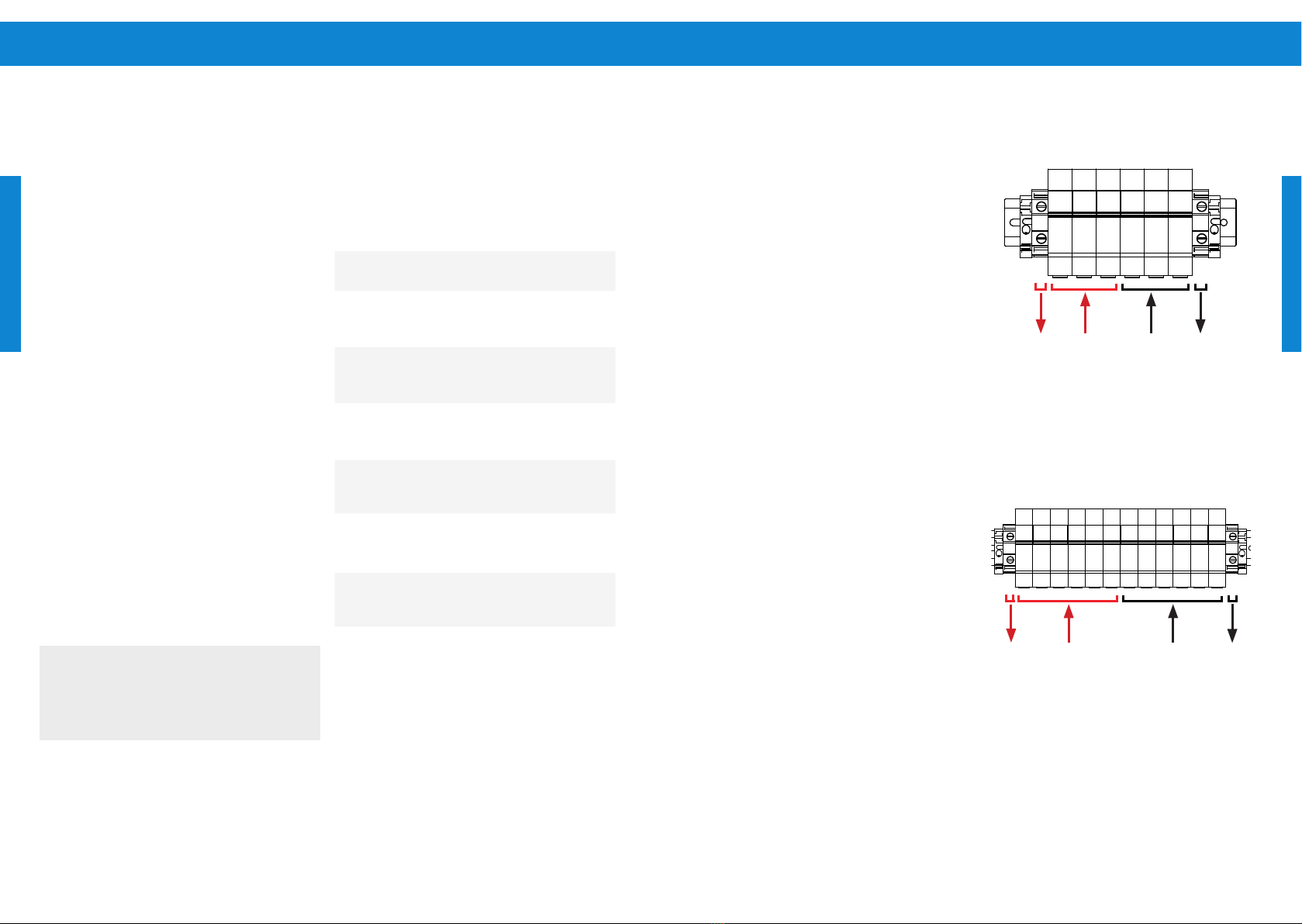
6 Scope of delivery
Depending on the reference, the scope of delivery
will be as specied below:
Table 1: Delivery list for PV Disconnect of max. 1
String:
Item Description Quantity
1PV Disconnect 400-50-1-S 1 unit
2Manual 1 unit
Table 2: Delivery list for PV Disconnect of max. 3
Strings:
Item Description Quantity
1PV Disconnect 400-50-3-S 1 unit
2Manual 1 unit
Table 3: Delivery list for PV Disconnect of max. 6
Strings:
Item Description Quantity
1PV Disconnect 400-50-6-S 1 unit
2Manual 1 unit
5 Safety Instructions
Safe operation of this product depends on its
correct transportation, installation, operation and
maintenance. Failure to follow these instructions can
be dangerous and/or void the warranty.
READ AND
FOLLOW ALL
INSTRUCTIONS!
Explanation of Warning Symbols
l WARNING – Disregard might lead to
injury or damage to the installation.
a CAUTION – Recommended to avoid
dysfunction or premature ageing of the
equipment etc.
When installing and using this electrical equipment,
basic safety precautions should always be followed,
including the following:
l WARNING – To reduce the risk of
injury, do not permit children to use this
product.
l WARNING – To reduce the risk of
electric shock, replace damaged cords
and cabling immediately.
l WARNING – It must be assured that
all grounding connections are properly
made and that the resistances meet local
codes or requirements.
The manual contains basic instructions which
must be observed during installation, operation
and maintenance. The manual should be
carefully read before installation and start-up
by the person in charge of the installation. The
manual should also be read by all other technical
personnel/ operators and should be available at
the installation site at all times.
Personnel qualication and training – All
personnel for the operation, maintenance,
inspection and installation must be fully qualied
to perform that type of job. Responsibility,
competence and the supervision of such
personnel must be strictly regulated by the user.
Should the available personnel be lacking the
necessary qualication, they must be trained and
instructed accordingly. If necessary, the operator
may require the manufacturer/supplier to
provide such training. Furthermore the operator/
user must make sure that the personnel fully
understand the contents of the manual.
Dangers of ignoring the safety symbols –
Ignoring the safety directions and symbols
may pose a danger to humans as well as to the
environment and the equipment itself. Non-
observance may void any warranties. Non-
observance of safety directions and symbols
may for example entail the following: Failure of
important functions of the equipment/plant;
failure of prescribed methods for maintenance
and repair; endangerment of persons through
electrical, mechanical and chemical eects;
danger to the environment because of leakage
of hazardous material; danger of damage to
equipment and buildings.
Safety-oriented operation – The safety directions
contained in the manual, existing national
regulations for the prevention of accidents as well
as internal guidelines and safety-regulations for
the operator and user must be observed at all
times.