Lotus CF4-78ET User manual

Translation of the original instructions
Installation and operating instructions
PROFESSIONAL COOKER WITH
ELECTRIC OVEN
CF4-78ET CFQ4-78ET CFC4-78ET CF6-712ETV CFQ6-712ETV CF6-712ET
CFQ6-712ET CFV4-78ET CFVQ4-78ET CFVC4-78ET CFV6-712ETV
CFVQ6-712ETV
Model LIBR.ISTR.CF70E
Code 563005403
Review 1
Edition date 14/01/2019
Language English
LOTUS S.p.A.
Via Calmaor, 46
31020 San Vendemiano
+39 0438 778020
+39 0438 778277

Contents
Translation of the original instructions
2
Contents
1 INTRODUCTION......................................................................................................................... 3
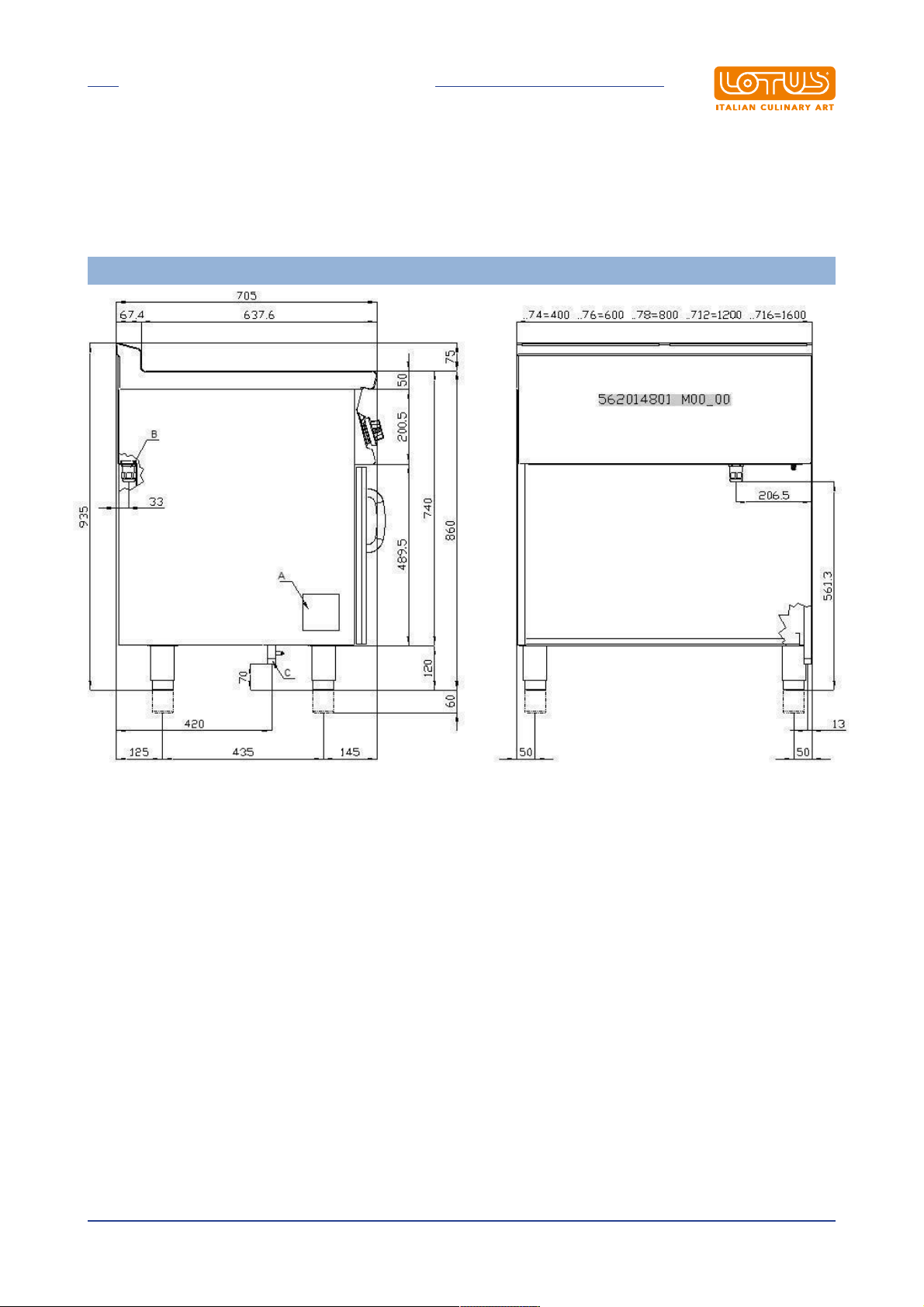
1.1 Installation drawing...................................................................................................................... 3
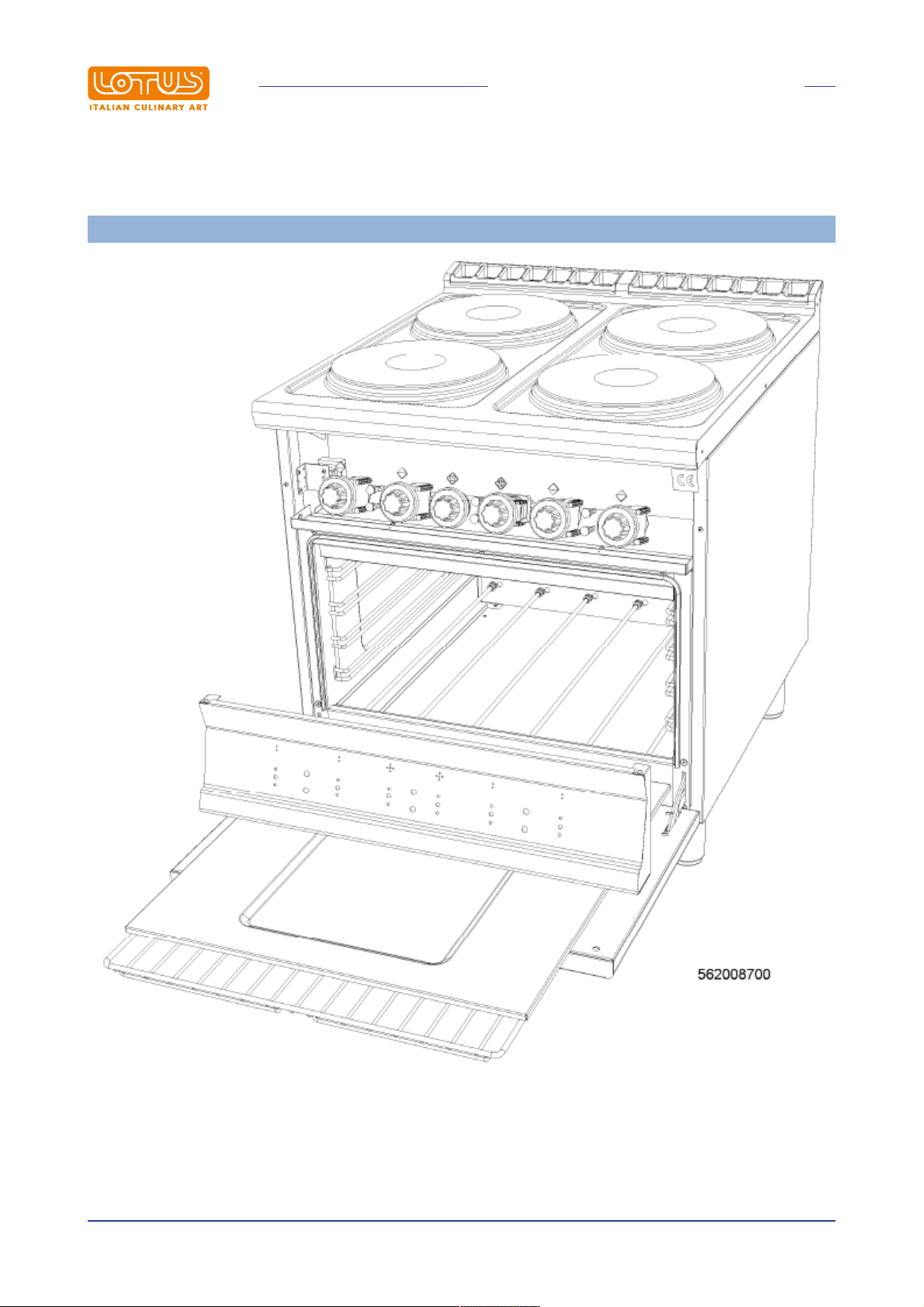
1.2 Components................................................................................................................................. 4
1.3 Example installation of the appliance........................................................................................... 12
2 GENERAL INFORMATION......................................................................................................... 13
2.1 Declaration of compliance............................................................................................................ 13
2.2 User information, RAEE Directive on waste electrical and electronic equipment ........................ 14
2.3 Technical data table..................................................................................................................... 14
3 INSTALLATION........................................................................................................................... 15
3.1 Delivery checks ............................................................................................................................ 15
3.2 Removing the packaging ............................................................................................................. 15
3.3 Mechanical installation ................................................................................................................. 15
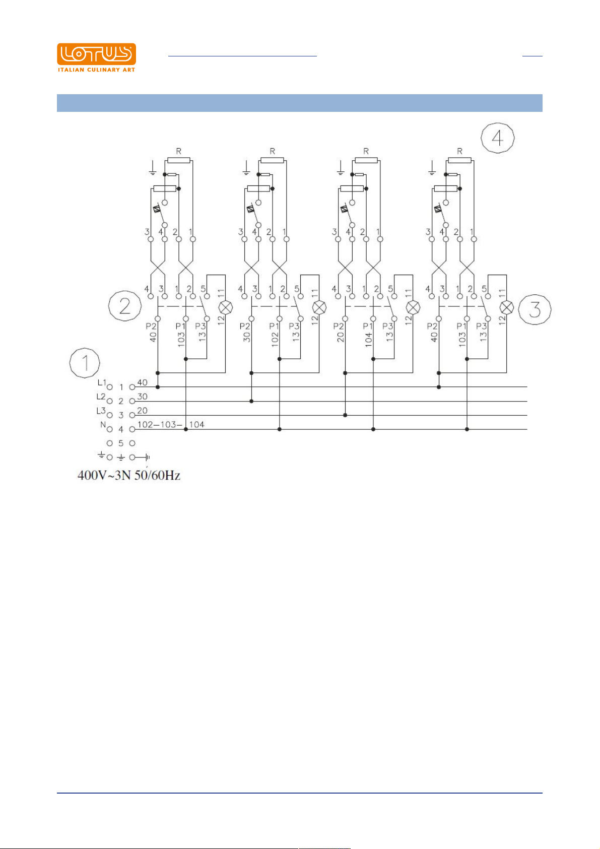
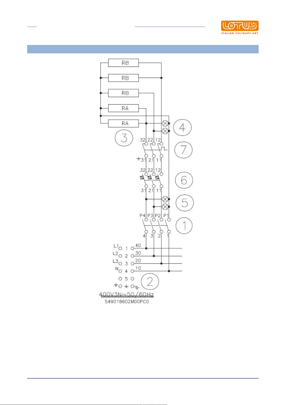
3.4 Electrical/gas connections ........................................................................................................... 15
4 INSTRUCTIONS FOR USE......................................................................................................... 17
4.1 General information ..................................................................................................................... 17
4.2 Lighting and adjusting the open rings.......................................................................................... 17
4.3 Glass-ceramic cooker hob........................................................................................................... 18
4.4 Turning on and adjusting the static oven ..................................................................................... 19
4.5 Turning on and adjusting the fan oven ......................................................................................... 20
4.6 Cooking table for the fan oven ..................................................................................................... 21
5 MAINTENANCE.......................................................................................................................... 23
5.1 Routine......................................................................................................................................... 23
5.2 Spare parts .................................................................................................................................. 24
6 CLEANING.................................................................................................................................. 25
6.1 Routine cleaning.......................................................................................................................... 25
6.2 Cleaning the glass ....................................................................................................................... 25
6.3 Maintenance suggestions............................................................................................................ 26
6.4 How to achieve a brilliant result in three simple steps:................................................................ 27
6.5 How to your SCHOTT CERAN® hob bright and shining for a long time...................................... 28

INTRODUCTION
Translation of the original instructions
3
1 INTRODUCTION
1.1 Installation drawing
FIG. 1 CF..-7..E
A Data Plate
B Electrical connection

INTRODUCTION
Translation of the original instructions
4
1.2 Components
FIG. B

INTRODUCTION
Translation of the original instructions
5
FIG. D
1 Square electrical plates
2 Round electrical plates
Radiant heating elements for glass-ceramic appliances

INTRODUCTION
Translation of the original instructions
6
WIRING DIAGRAM CF...4-78ET , CF...Q4-78ET
1 Power supply terminal board
2 Switch
3 White indicator light
4 Electrical plate

INTRODUCTION
Translation of the original instructions
7
WIRING DIAGRAM CF…6-712ETV, CFQ...6-712ETV , CF6-712ET , CFQ6-712ET
1 Power supply terminal board
2 Switch
3 White indicator light
4 Electrical plate

INTRODUCTION
Translation of the original instructions
8
WIRING DIAGRAM CF…C4-78ET
1 Power supply terminal board
2 Plate
3 Power regulator
5 Residual heat indicator light

INTRODUCTION
Translation of the original instructions
9
WIRING DIAGRAM OVEN GN 2/1
1 Switch
2 Power supply terminal board
3 Heating element
4 White indicator light
5 Green indicator light
6 Thermostat
7 Safety thermostat

INTRODUCTION
Translation of the original instructions
10
WIRING DIAGRAM OVEN GN 3/1
1 Switch
2 Power supply terminal board
3 Heating element
4 White indicator light
5 Green indicator light
6 Thermostat
7 Safety thermostat

INTRODUCTION
Translation of the original instructions
11
VENTILATED ELECTRICAL OVEN
1 Switch
2 Condenser
3 Power supply terminal board
4 Switching terminal board
5 Motor
6 Heating element
7 White indicator light
8 Green indicator light
9 Safety thermostat
10 Thermostat

INTRODUCTION
Translation of the original instructions
12
1.3 Example installation of the appliance

GENERAL INFORMATION
Translation of the original instructions
13
2 GENERAL INFORMATION
2.1 Declaration of compliance
The manufacturer declares that the appliances comply with the requirements of the regulation GAR
2016/426 for the gas part and directive 2014/30/EU,2014/35/EU for the electrical part. Installation must be
performed in compliance with current regulations, especially with regard to ventilation of the premises and
the exhaust gas evacuation system.
·Read the warnings in this manual carefully. They provide important information about safe installation,
use and maintenance.
·The instruction manual must be kept for the entire duration of the equipment and made available to users
for every possible consultation. The manual should be consulted for any information concerning
installation, use and maintenance of the appliance.
·After removing the packaging, check the integrity of the equipment.
·All packaging materials (plastic bags, polystyrene, staples, etc.) must be disposed of in compliance with
current regulations.
·Before connecting the appliance, make sure that the information on the data plate matches the electricity
and gas mains where the appliance is installed. The manufacturer accepts no liability if the
equipment is not connected in accordance with current regulations.
·Always keep all parts of the equipment clean to avoid the risk of oxidation/rust and/or aggression by
chemical agents.
·The equipment must only be used by personnel trained for the purpose.
·The installation must be implemented by professionally qualified personnel in accordance with
the manufacturer's instructions and current reference standards.
·The electrical safety of this equipment is only ensured when it is correctly connected to an effective
ground/earth system as required by current electrical safety standards. The manufacturer cannot be held
liable for any damage caused if the system is not connected to ground/earth.
·Before carrying out any cleaning or maintenance tasks on the equipment, unplug it from the electricity
mains. In the event of faults or malfunctions, always deactivate the appliance.
·Repair work of any kind must only be performed by qualified personnel.
·This appliance must only be used for its expressly intended purpose for cooking or heating food. Any
other use is considered improper.
·The appliance is intended for professional use and must be used by trained personnel.
·The installation and possible transformation to another power supply voltage (if envisaged), or
transformation for operation with another type of gas, must be implemented exclusively by qualified and
authorised professional personnel.
·Before using the appliance, carefully clean all surfaces intended to come into contact with food.
·The manufacturer declines any and all liability for any direct or indirect damage resulting from improper
use of the equipment. The manufacturer declines any and all liability for damage caused by incorrect
installation, tampering, poor maintenance and unskilled use. Moreover, the manufacturer declines any
liability for possible inaccuracies that may be contained in this booklet attributable to errors in
transcription or printing and equally reserves the right to make any changes to the product it deems
useful and/or necessary without compromising its essential characteristics.
·The manufacturer cannot be held liable for any damage caused by failure to comply with these
basic standards and all other use and maintenance standards contained in this booklet.

GENERAL INFORMATION
Translation of the original instructions
14
2.2 User information, RAEE Directive on waste electrical and
electronic equipment
With regard to the regulatory framework of reference of the European Community, we remind the user of the
following:
·Used AAE (Electrical and Electronic Equipment) products must be collected separately
·The user can carry out this collection in the RAEE collection systems and return the equipment to the
distributor when purchasing a new one
·Plus being RoHS compatible, (in accordance with Directive 2011/65/EU on the restriction of the use of
certain hazardous substances in electrical and electronic equipment) the potential effects on the
environment and human health may be due to the misuse of the same equipment or parts of it
·The symbol next to the rating plate indicates the obligation of separate collection
·The penalties provided for in the event of improper disposal of RAEE (Waste Electrical and Electronic
Equipment) are those provided for by the national transpositions of European Directives 2012/19/EU
2.3 Technical data table
Technical data table PCCF S70E
MODEL DIMENSION
SPOWER SUPPLY MAXIMUM INPUT
(A)
MAXIMUM
POWER
(kW)
Emissivity Silicon POWER
SUPPLY CABLE
CF4-78ET 80x70x90h 400V~3N 50/60 Hz 27,8 15,4 / 5 x 4 mm²
CFQ4-78ET 80x70x90h 400V~3N 50/60 Hz 27,8 15,4 / 5 x 4 mm²
CFC4-78ET 80x70x90h 400V~3N 50/60 Hz 27 15 / 5 x 4 mm²
CF6-712ETV 120x70x90h 400V~3N 50/60 Hz 33 20,6 / 5 x 6 mm²
CFQ6-712ETV 120x70x90h 400V~3N 50/60 Hz 33 20,6 / 5 x 6 mm²
CF6-712ET 120x70x90h 400V~3N 50/60 Hz 33 22,5 / 5 x 6 mm²
CFQ6-712ET 120x70x90h 400V~3N 50/60 Hz 33 22,5 / 5 x 6 mm²
CFV4-78ET 80x70x90h 400V~3N 50/60 Hz 30,14 15,7 <70 5 x 4 mm²
CFVQ4-78ET 80x70x90h 400V~3N 50/60 Hz 30,14 15,7 <70 5 x 4 mm²
CFVC4-78ET 80x70x90h 400V~3N 50/60 Hz 29,28 15,3 <70 5 x 4 mm²
CFV6-712ETV 120x70x90h 400V~3N 50/60 Hz 30,67 20,9 <70 5 x 4 mm²
CFVQ6-712ETV 120x70x90h 400V~3N 50/60 Hz 30,67 20,9 <70 5 x 4 mm²

INSTALLATION
Translation of the original instructions
15
3 INSTALLATION
3.1 Delivery checks
On delivery, it is important to check the following:
·External conditions of the packaging
·The general status of the equipment
·The conformity of the model with the information in the technical data plate and the instruction manual
·The conformity of the equipment and components to the order form
3.2 Removing the packaging
While removing the packaging, take care not to damage the appliance. Remove the protective film from the
stainless steel and eliminate any traces of glue. Do not smoke. Perform this operation away from sources of
heat and wear protective gloves. Do not disperse packaging material in the environment, keep it out of the
reach of children and dispose in compliance with current legislation.
3.3 Mechanical installation
Place the appliance on a flat base. Adjust and stabilise the appliance by acting on the support feet. Make
sure that the surrounding walls and/or equipment are capable of withstanding the heat emitted by this
appliance. Connect the water supply (if necessary).
Caution
Do not install the appliance near equipment/machines used in cold processes. If the appliance
has to be installed close to cold process equipment, it is advisable to install non-combustible
thermal insulating material and/or neutral elements between them.
3.4 Electrical/gas connections
Before being offered for sale on the market, the appliance was subjected to gas and electrical testing (as
required). The appliance is supplied without a power cable. The installation technician must connect the
equipment in compliance with current safety regulations on the basis of the power of the appliance.
Note
The ID plate is located in the compartment inside the door for appliances with compartments, or on
the left side for appliances with an oven or a top. A second plate with the model and serial number is
located inside the dashboard and a third is included with the certificate of conformity. The serial
number can also be tracked from the sales document (after 2008). The plate has all the data needed
for correct electrical installation. The installation and possible conversion to another power supply
voltage (if envisaged) must be implemented exclusively by professionally qualified and authorized
personnel. Before using the appliance, carefully clean all surfaces intended to come into contact with
food.

INSTALLATION
Translation of the original instructions
16
Warning
Installation operations, any conversion to other types of gas and start-up must only be
performed by qualified personnel, in accordance with current regulations.
Gas systems, electrical connections and premises where the appliances are installed must comply with
current regulations in the country of installation; in particular, the appliance must be installed in a room with
good ventilation, if possible under a suction hood to ensure complete evacuation of the exhaust gases
formed during combustion. The air required for combustion is 2 m3/h per kW of installed power. The
appliance can be installed alone or in series with other appliances in our production range. A minimum
distance of 10 cm between appliances must be respected to prevent contact with any walls made of
flammable material; furthermore, appropriate measures should also be adopted to ensure the thermal
insulation of flammable parts, such as the installation of heat shields; take special care to ensure that
appliances are installed in an appropriate and safe manner. The support feet can be adjustable in height and
any unevenness can therefore be eliminated.
ELECTRICAL CONNECTION
Caution
In accordance with international provisions, when connecting the appliance an automatic
device must be installed up-line of it so that the device can be fully disconnected from the
mains; this device must have a contact aperture of at least 3 mm.
The connection terminal is located behind the rear wall. Proceed as follows to install the power supply cable:
·Remove the rear panel.
·Pass the new connection cable through the cable gland, connect the leads to the corresponding terminal
on the terminal block and fasten them securely.
·Lock the cable with the cable gland and refit the panel. The earth/ground lead must be longer than the
others so that if the cable gland breaks it is disconnected after the power cables.
Note
Make sure that the mains voltage complies with the data on the appliance's ID plate and that there is
good conductivity to earth/ground. Pay attention when inserting leads to ensure they do not obstruct
the normal course of work and routine appliance cleaning operations. Also make sure that the power
cable is never pulled taut and is not placed in contact with sources of heat.
Note
The connection cable must have the following characteristics: it must be silicone type (to
withstand temperatures of 180 °C), and must have an appropriate cross-section for the power
of the appliance (see technical data table).
EQUIPOTENTIAL
The appliance must be connected to an equipotential system. The connecting screw is located on the rear of
the appliance and is marked by the yellow symbol above it.
Warning
The manufacturer is not liable for and does not indemnify damages caused by incorrect
inadequate installations that do not comply with these instructions.

INSTRUCTIONS FOR USE
Translation of the original instructions
17
4 INSTRUCTIONS FOR USE
4.1 General information
This appliance must only be used for its expressly intended purpose for cooking or heating food. Any other
use is considered improper. The appliance is also intended for industrial use and must only be used by
personnel trained for use and aware of the risks that the hot element entails.
Warning
The appliance operates at high temperatures, so the following is necessary:
·Pay attention to the areas surrounding the hot surface during routine normal operation
(danger of scalding);
·RISK OF BURNS Do not touch hot surfaces floor with your hands or other parts of the body
to avoid burns caused by high temperatures;
·After switching off the appliance, wait for a sufficient time for it to cool before carrying out
any cleaning or maintenance operation.
4.2 Lighting and adjusting the open rings
On the front panel, a plate is indicated above the knob to which it corresponds, marked by the index
·Turn on the switch located upstream of the appliance. Turn the control knob that corresponds to the plate
from "O" to the desired heating level, between 1 and 6
·The indicator light turns on as soon as the appliance is powered
Note
To start up the plate, we recommend starting all plates and operating them at maximum power in
order to eliminate any moisture that might have remained in the insulation of the heating elements.
It is recommended to start the plate at the maximum level and, once the temperature is reached, turn
the control lever to the desired level. Turn the knob to "O" to switch off the plate.
Warning
Each plate has a temperature limiter that interrupts the current supply once a temperature of
450°C is reached
Caution

INSTRUCTIONS FOR USE
Translation of the original instructions
18
·Never operate the electrical plate without a pot
·The pot must have a smooth bottom with a diameter suitable for the plate (never smaller)
4.3 Glass-ceramic cooker hob
On the front panel, a plate is indicated above the knob to which it corresponds, marked by the index
·Turn on the switch located upstream of the appliance. Turn the control knob that corresponds to the plate
from "O" to the desired heating level, between 1 and 6
·The indicator light turns on as soon as the appliance is powered
·The plates are formed by a core and a ring; turning the knob as shown above turns on only the core of
the plate; turning the knob past position "6" also turns on the ring and the temperature can be adjusted
again between pos. "1" and "6"
Note
·Each plate is connected to a power regulator, which makes it possible to select from among 6
different temperatures. Higher temperatures are recommended at the start of cooking
·Each plate has a temperature limiter that is triggered when the temperature that was reached could
damage the glass
Warning
When the glass surface heats up, the luminous residual heat indicator turns on that
corresponds to the plate in use. This indicator remains on as long as the glass is hot, even if
the plate is off, to prevent the risk of burns

INSTRUCTIONS FOR USE
Translation of the original instructions
19
Note
·It is recommended to use flat based receptacles, as those with a concave or rounded base
increase the cooking time and energy use
·Do not use pots or any receptacle with an aluminium or tin covered base
·Do not use terracotta pots as they could break or crack and become unhygienic
·It is recommended to use stainless steel pans with a smooth, flat base with a diameter suitable for
the heating area
·If cast iron pans are used, make sure not to slide them on the glass to prevent scratches
·Make sure that the bottom of the pot is dry before placing it on the hob
·Prevent the glass from being struck by objects with edges or tips
·Never cover the glass with aluminium foil or similar items during use
·The glass must be washed with liquid degreasers, vinegar and lemon based acids, that are
suitable for cleaning ceramic and glass. It is recommended to perform cleaning when the glass is
not completely cold, as residual food, burnt grease or other items can be softened with a moist
cloth and removed while hot using a common scraper to prevent the glass surface from being
tainted. Do not use abrasive or corrosive detergents.
4.4 Turning on and adjusting the static oven
·Turn the control knob to the right and set the desired temperature
·Also turn the knob of the selector, setting one of the three positions
Top + bottom heating element
Bottom heating element
Top heating element

INSTRUCTIONS FOR USE
Translation of the original instructions
20
4.5 Turning on and adjusting the fan oven
The hot air put in circulation by the fan is distributed in the entire oven chamber, ensuring even cooking. The
uniform heating of the chamber makes it possible to cook different foods at the same time on different levels.
Turn the knob on the panel from “O” to the desired position between 50° and 300°C, the white and green
indicator lights will turn on
·The green indicator light indicates that the appliance is powered
·The white indicator light indicates that the heating element is functioning and when it turns off, this means
that the temperature has been reached. Turn the knob to “O” to switch off the appliance
MECHANICAL TIMER
The cookers have an acoustic timer that can signal a maximum time of 120 minutes. Turn the knob to the
right, position it to the preselected time, between 0 and 120 minutes (see figure); once the set time has
elapsed, the acoustic timer activates
Caution
When the oven is operating, the door must not remain open as it could overheat and damage
the knobs and the protective plates
This manual suits for next models
11
Table of contents
Other Lotus Oven manuals