PAGE 4 of 28
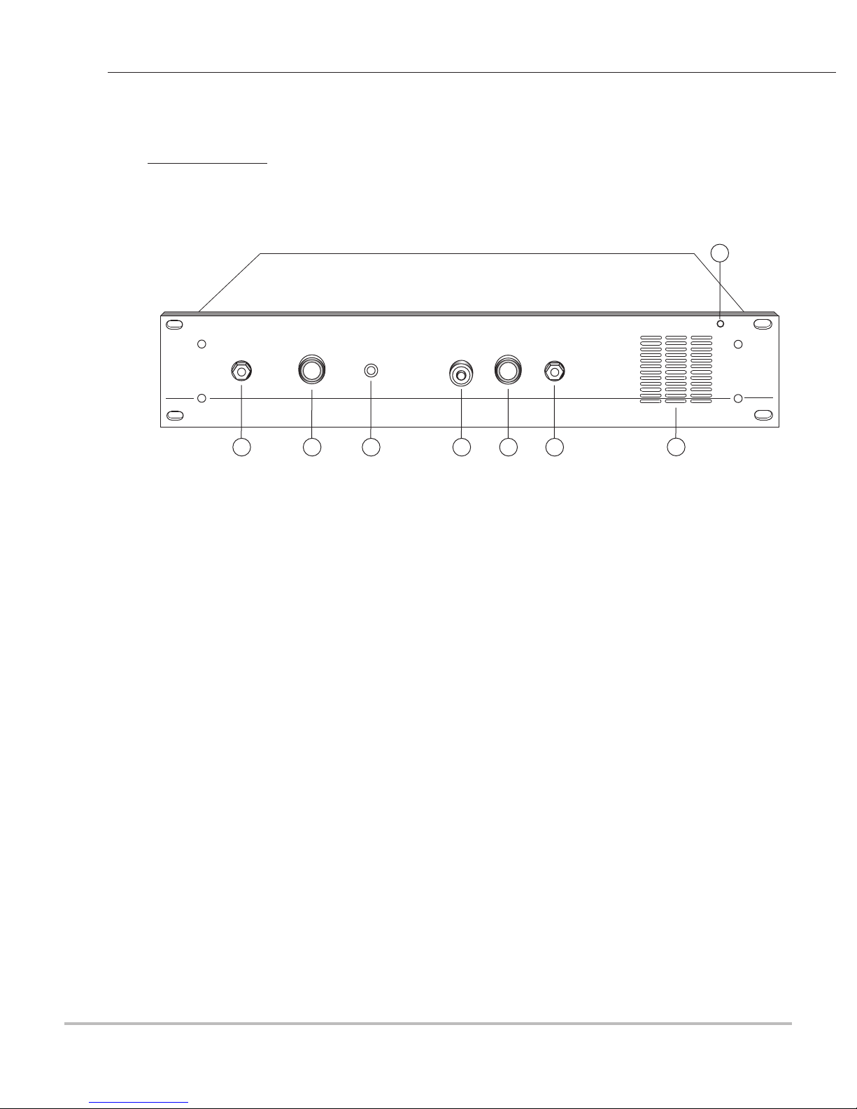
[16] Keyswitch Turns ON power to the unit. Also
Turns ON the Sonalert Buzzer [4].
Switch operations:
Position 1- Power OFF
Position 2- Power ON
Position 3-Power and Sonalert Buzzer ON
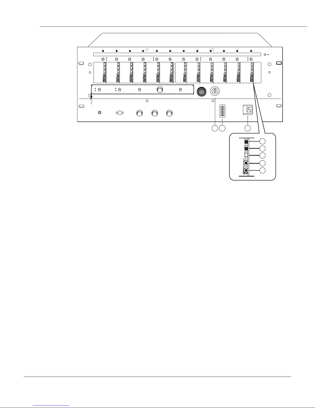
[17] Audio Level Indicator Shows the level of the audio of the zone in test, It contains 10 level
segments (7 green and 3 red) that illuminate and move up and down
the scale, depending upon the amount of signal it receives. Settings
should be made so that the level of the ambient sound on test does
not reach the red segments. The unit will go into alarm when the
audio reaches the last red segment.
[18] Alarm Delay Indicator Indicates the length of the alarm delay setting.
[19] Alarm Delay Setting Pushbutton Used to set the length of alarm delay. The switch can be pushed to
a maximum of 32 times. It must be pushed and released quickly.
The switch will go to the next step or more if not released
immediately.
[20] Night Sensitivity Setting Pushbutton Used to set the audio threshold sensitivity for nighttime. The
Day/Night Sensitivity Switch [9] must be in the UP position. The
switch can be pushed to a maximum of 32 times. Additional pushes
have no effect on the switch.
[21] Day Sensitivity Setting Pushbutton Used to set the audio threshold sensitivity for daytime. The
Day/Night Sensitivity Switch [9] must be in the Down position.
The switch can be pushed to a maximum of 32 times.
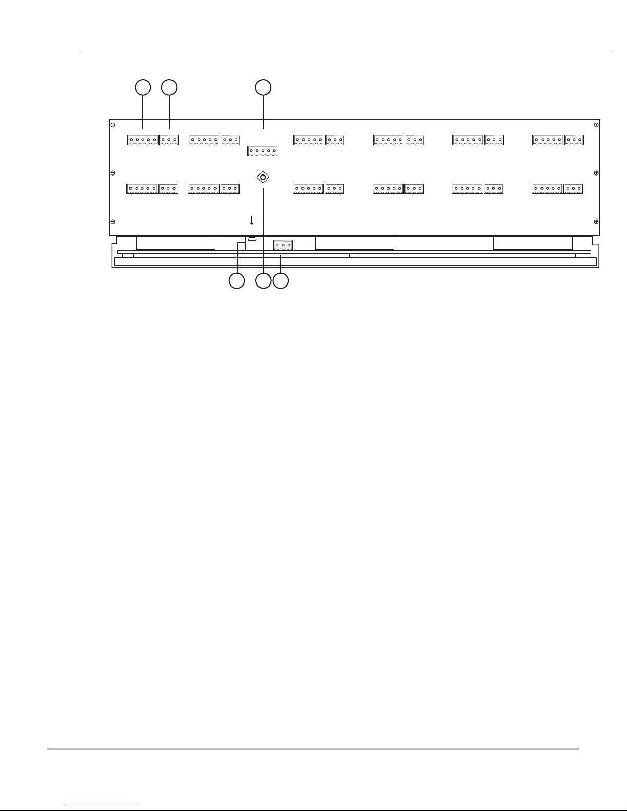
[22] Audio Alarm Output Jack Provides DC output corresponding to the audio alarm level after the
filter network. Used to set and test the level of audio as seen at the
Audio Level Indicator [17]. A test cable is provided to connect
between this jack and Audio Input Jack[6].
[23] Alarm Delay Output Jack Provides output to the Alarm Delay Input Jack[8]. Used to set the
time delay feature and for checking the time delay setting, which is
variable between 0.1-3.2 seconds.
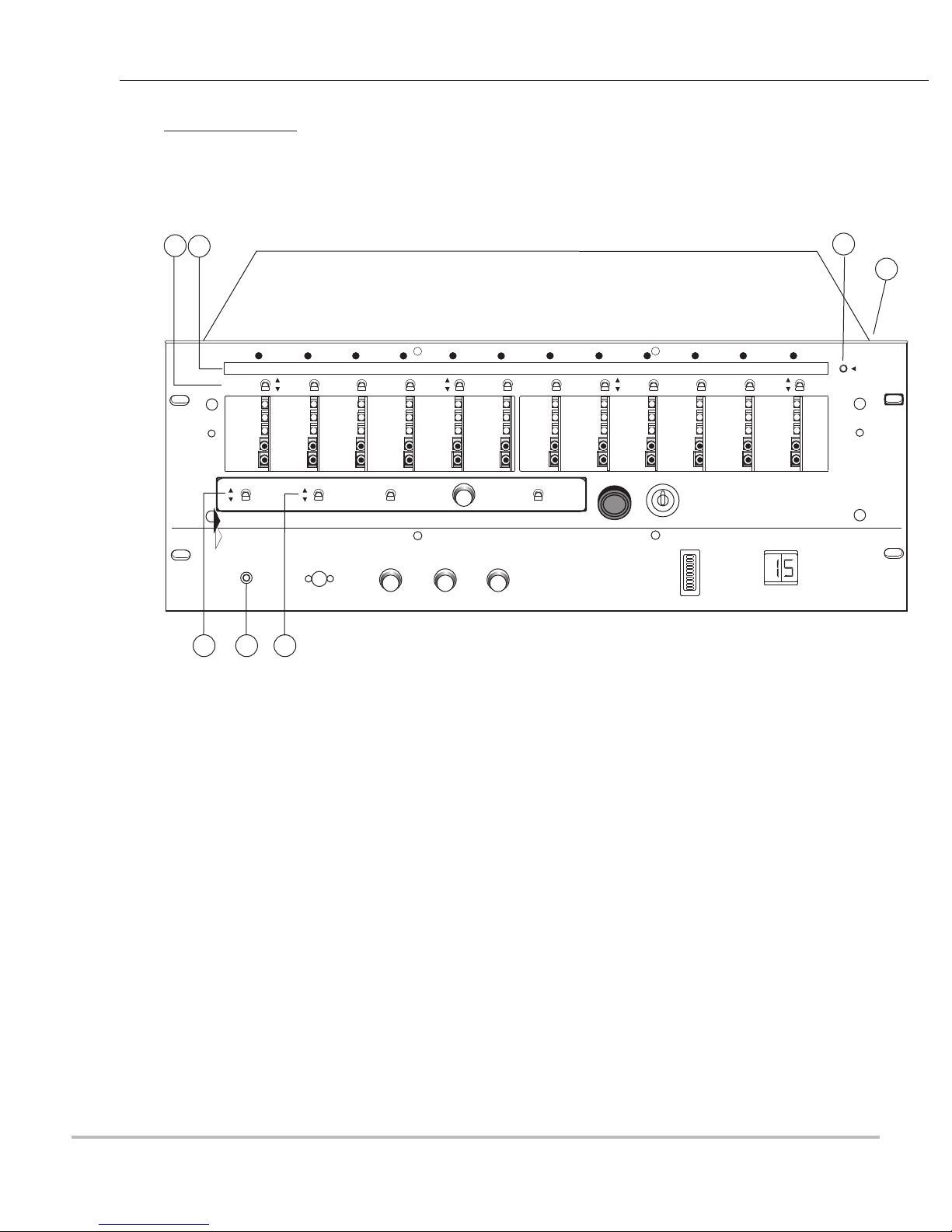
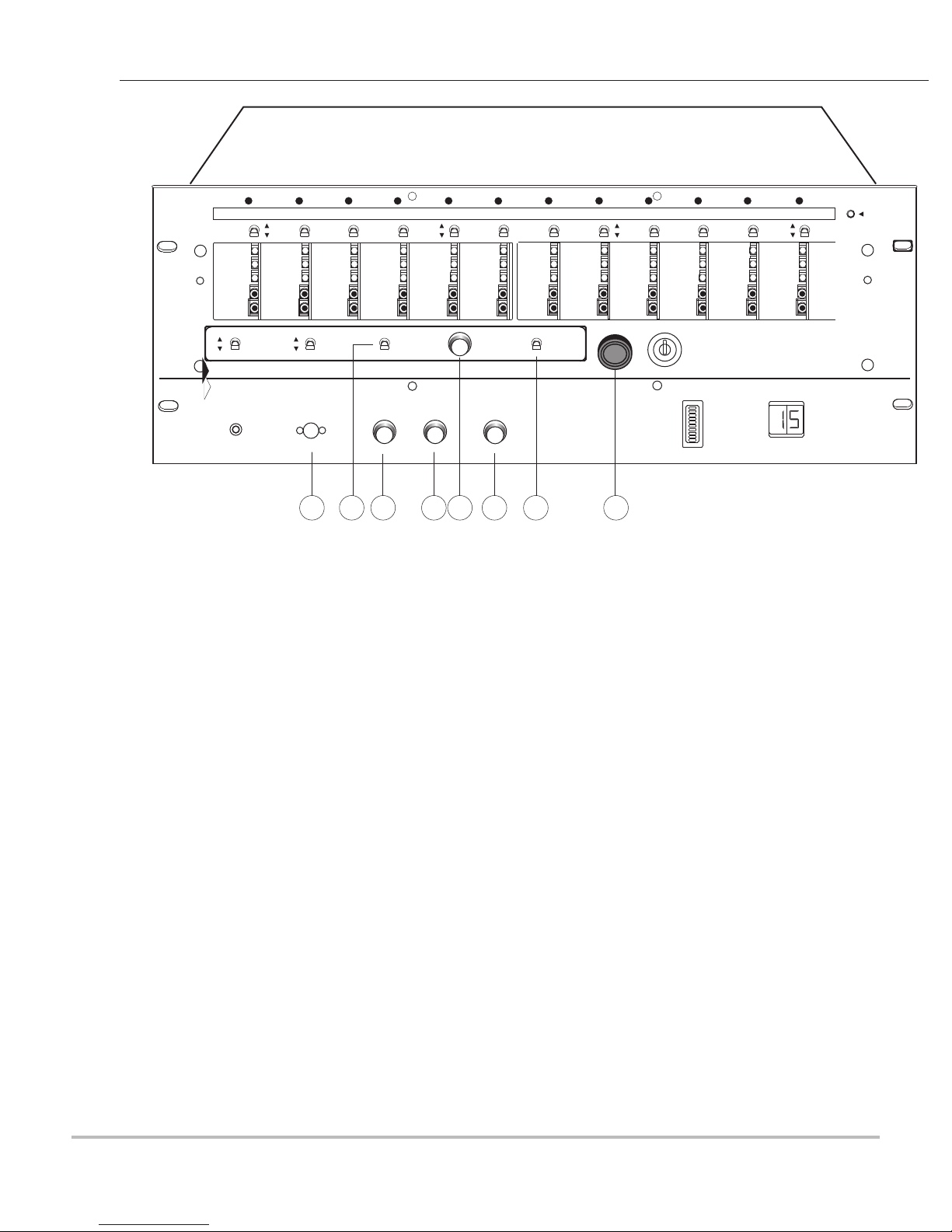
Fig. 1 DG-12 Front Panel LayoutII
16 17 18
19
20
21
22
23
POWER
SET-UP CONTROLS
MONITOR
TALKBACK
ZONES
E
LOUROE
LE CTR O N ICS
TIME
DELAY
THRESHOLD
SENSITIVITY SENSITIVITY RESET NON-ALARM
MONITOR
ALARM INPUT ALARM DELAY INPUT TIME RESETTRIGGER POWER
ALARM LEVEL ALARM DELAY
DG-12II
AUTO-RESET OFF
ON
LOUROE ELECTRONICS 6955 VALJEAN AVENUE, VAN NUYS, CA 91406 TEL (818) 994-6498 FAX 994-6458
(818)
INSTALLATION AND OPERATING INSTRUCTIONS
DG-12II 2/08
ON/AUDIO ALERT