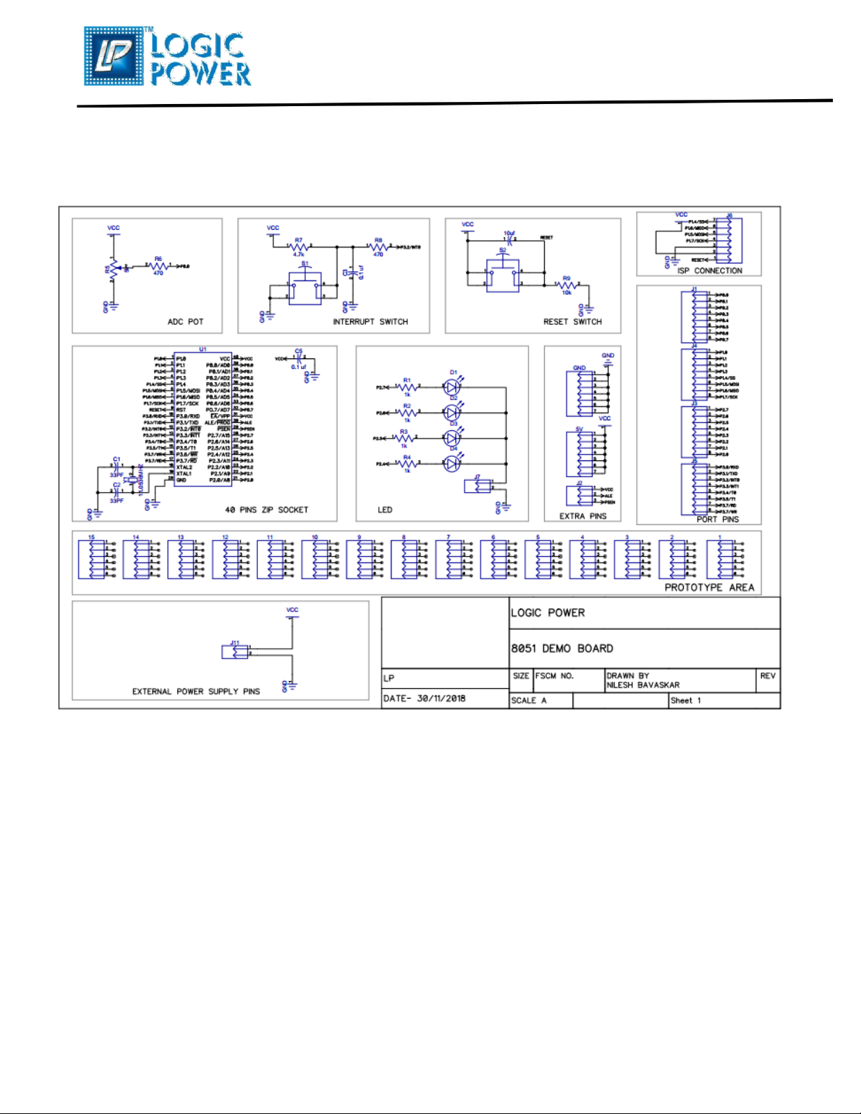
LP 8051 User manual

8051 DEMO BOARD
8051 DEMO BOARD
User’s Guide

8051 DEMO BOARD
Table of Contents
Chapter 1:
Introduction
1.1
Welcome ………………………………………………………………………………….
03
1.2
8051 Demo Board …………………………………………………………………..
04
1.3
Sample Devices ………………………………………………………………………
04
1.4
Why 8051 Demo Board?………………………………………………………...
05
Chapter 2:
Hardware Details
2.1
MCU ZIP Socket…………………………………………………………………….
06
2.2
Power Supply………………………………………………………………………….
06
2.3
Display LEDs…………………………………………………………………………..
07
2.4
Analog Input……………………………………………………………………………
07
2.5
Switch……………………………………………………………………………………..
07
2.6
Port Extension Pins…………………………………………………………………
07
2.7 Connector………………………………………………………………………………..
07
Chapter 3:
Board Layout and Schematic………………………………………………………… 08
Logic Power Contact Us……………………………………………………………..
10
Page 2of 10

8051 DEMO BOARD
Introduction
1.1 Welcome
Thank you for purchasing the 8051 Demo Board from Logic Power!!
The 8051 Demo Board is a simple board which demonstrates the
capabilities of the 40-Pin AT89C51/AT89S8252. Sample
programs are provided to demonstrate the unique features of the
supported devices.
The ADVANCE 40-Pin™ Demo Board comes with the following:
8051 Demo Board
Sample devices (AT89C51/AT89S8252)
CD-ROM, which contains:
Sample programs
8051 Demo Board User’s Guide
If you are missing any part of the kit, please contact your nearest
Logic Power office listed in the back of this user guide for help.
Page 3of 10

8051 DEMO BOARD
1.2 8051 Demo Board
The 40-Pin Demo board is specially designed for 8-bit 8051MC and MCS-51
microcontrollers. Board also support Atmel microcontroller pin compatibles with 8051.
Key Features:
• 40-Pin Zif Socket for easy inserting and removing the MCU
• ISP connection for connecting demo board with the PRESTO
• 5V DC external power supply for providing the external power to the demo board
• Four Red LEDs connected to PORT2, i.e. 2.7, 2.6, 2.5 & 2.4
•5KΩ POT connected to the R0.0 pin of PORT0 for analog inputs
(Only for inbuilt ADC ICs eg.AT89LP511RD2-ED2-ID2)
• Extra On-board power pins of 5V and GND for providing power to the external device
• PIN number 9 RST pin is used for hardware reset
• INT0 external interrupt switch
• 11.0592 MHz external crystal
• Extra female burg strips for PORT extensions
1.3 Sample Devices
The device type may change but will generally include AT89C51
and AT89S8252, 40-pin DIP device.
Page 4of 10

8051 DEMO BOARD
1.4 Why 8051 Demo Board?
8051 Demo Board is comes with 40-Pin Zip socket which
provides easy insertion and remove of MCU.
Board comes with AT89C51/AT89S8252 and Board also support
40-Pin microcontroller pin compatibles with
AT89C51/AT89S8252.
5kΩ pot for analog input from VDD to GND.
ISP connection for connecting demo board with the PRESTO.
Page 5of 10

8051 DEMO BOARD
Hardware Details
The 8051 Demo Board hardware is extremely simple and is intended to
illustrate the ease of use of 8bit AT89C51 and AT89S8252, 40-Pin PIC
MCUs. Board also support 40-Pin DIP microcontroller pin compatible
with AT89C51 / AT89S8252.
The features of the board hardware elements are as follows:
2.1 MCU ZIP Socket
It’s very hard to remove one microcontroller and solder another one
on PCB, when first one gets damaged or need to work with different
microcontroller. 8051 demo board provides 40-Pin Zip socket to
easily add or remove MCU, it provides Zero Insertion Force for
adding and removing the MCU.
2.2 Power Supply
•A +5V, 500 mA regulated DC power supply can be connected to the
pins provided at the top right of board.
•An internal power supply can also be provided by using PRESTO
(Please check particular Programmers User Guide to set an internal
power supply, also we recommend you to use an EXTERNAL Power
Supply for your demo board).
(To Purchase any programmer/debugger from Logic Power,
please email your requirement to the below email Id.:
sales@logicpower.in or Buy it from our website directly:
www.logicpower.in)
Page 6of 10

8051 DEMO BOARD
2.3 Display LEDs
Four LEDs are provided on board, connected to the PORT2, i.e. P2.7,
P2.6,P2.5 & P2.4 [Enabled through Jumper (J11)]. LED connected on
PORT2 is also used for an indication of Power ON, it turns ON, when
powered through an external source and while programming the
device.
2.4 Analog Input
8051 demo board is provided with 5kΩ, is connected to AN0 channel
of A/D module. POT can generate different analog voltage levels from
VDD to GND to provide analog input to A/D module.
2.5 SWITCH
Demo board has 2 switches.
RST switch: - to hard reset the processor.
INT0 switch:- for external interupt switch.
2.6 PORT EXTENSIONS
8051 Demo Board is provided with port extensions.
2.7 CONNECTOR
By way of the header connector, the KEIL PRESTO can be connected
for low-cost debugging.
Page 7of 10

8051 DEMO BOARD
Board Layout
The following figures show the parts layout (silkscreen) for 8051 Demo
Board.
Figure 3.1 8051 Demo Board Layout
Fig.: 3.1
Page 8of 10

8051 DEMO BOARD
Figure 3.2. 8051 Demo Board Schematic
Fig.: 3.2
Page 9of 10

8051 DEMO BOARD
Please contact us for any query related to our Product.
Pune Office
#8, Sujit Complex,
S.No.60/7/1A/2,Vadgaon Budruk, Near
Vadgaon Bridge, Sinhagad Road, Pune
411041. Maharashtra. India.
Cell. No.:+91-9422943523/8551021420/1
Bangalore Office
#101, Aishwarya Neela, 14th Cross,
Neeladri Nagar, Opp. Ajmera Infinity,
Electronics City, Phase I, Bangalore-
560100. Karnataka. India.
Cell. No.: +91-9972569282
Page 10 of 10
Table of contents