LS Industrial Systems GIPAM User manual

User Manual
GIPAM•GIMAC-II•GMPC-III
User Manual 2003 / (01) 2003.10 Printed in Korea STAFF
LG Industrial Trading (Shanghai) Co., Ltd China
Address: Room1705-1707, 17th Floor Xinda
Commerical Building No 318, Xian Xia Road Shanahai
Tel: 86-21-6252-4291 Fax: 86-21-6278-4372
e-mail: hgseo@lgis.com
Safety Instructions
For your safety, please read user’s manual thoroughly before operating.
Contact the nearest authorized service facility for examination, repair,
or adjustment.
Please contact qualified service technician when you need maintenance.
Do not disassemble or repair by yourself!
Any maintenance and inspection shall be performed by the personnel having
expertise concerned.
LG Industrial Systems Shanghai Office China
Address: Room1705-1707, 17th Floor Xinda Commerical Building
No 318, Xian Xia Road Shanahai, China
Tel: 86-21-6278-4370 Fax: 86-21-6278-4301
LG Industrial Systems Guangzhou Office China
Address: Room 303, 3F, Zheng Sheng Building, No 5-6, Tian He
Bei Road, Guangzhou, China
Tel: 86-20-8755-3410 Fax: 86-20-8755-3408
Room 303, 3F
sdhwang@lgis.com
2003-10
Specifications in this catalog are subject to change without notice due to
continuous product development and improvement.
User Manual (GIPAM•GIMAC-II•GMPC-III)

GIPAM USER MANUAL
(Digital Integrated Protection
& Monitoring Equipment)
GIPAM User Manual

2
GIPAM User Manual
1. Summary ………………………………………………………………………… 3
2. Characteristics …………………………………………………………………. 3
3. Main Features …………………………………………………………………… 4
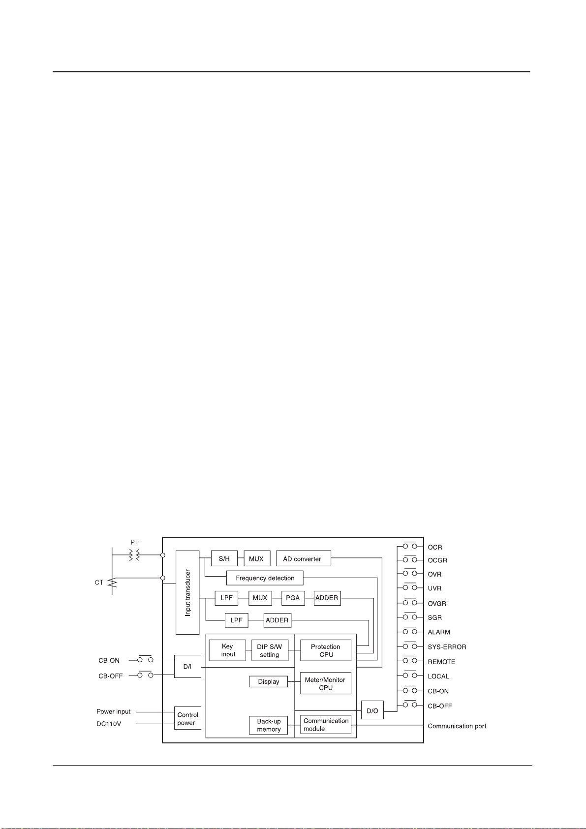
4. External view and System structure
4.1 External view and part name ……………………………………………………………… 5
4.2 System structure …………………………………………………………………………….. 5
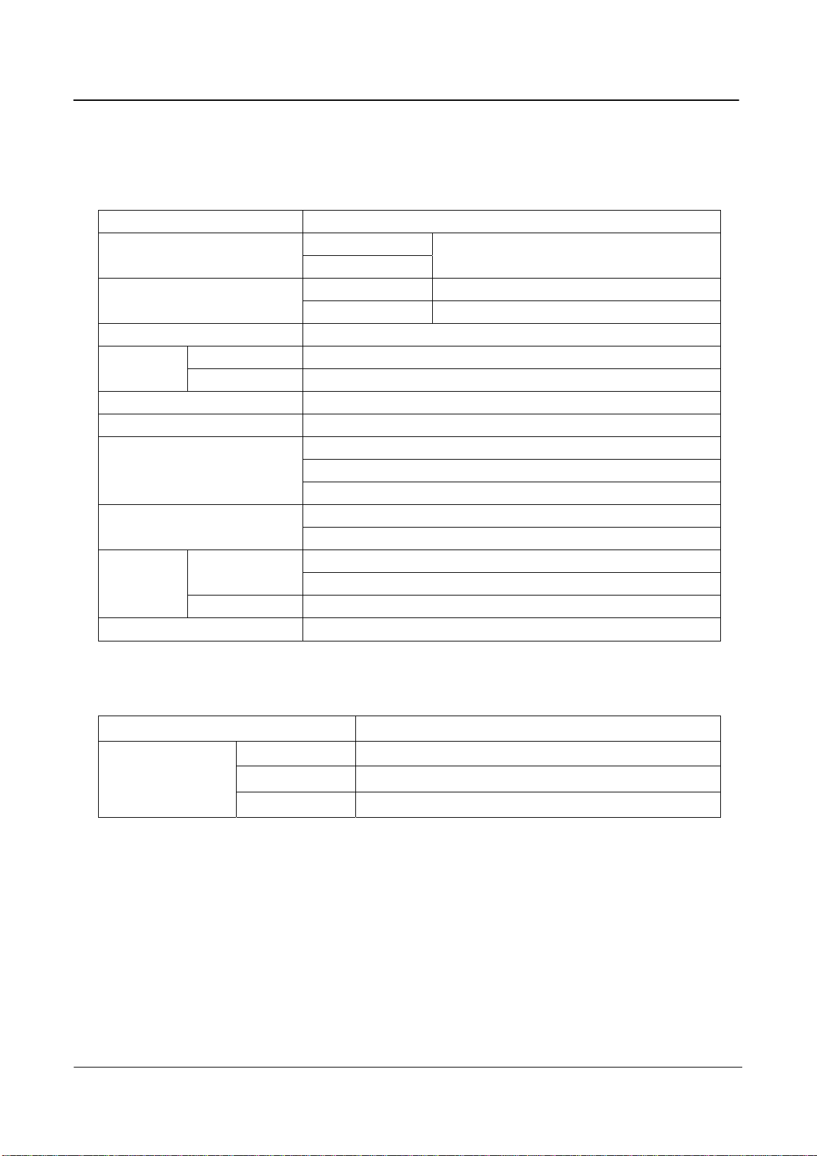
5. Capacities
5.1 Measuring Part ………………………………………………………………………………. 6
5.2 Protection Part ………………………………………………………………………………. 8
6. Operation
6.1 Measuring Part ……………………………………………………………………………….. 9
6.2 Protection Part ……………………………………………………………………………… 12
7. Installation and operation
7.1 Installation Method …………………………………………………………………………. 23
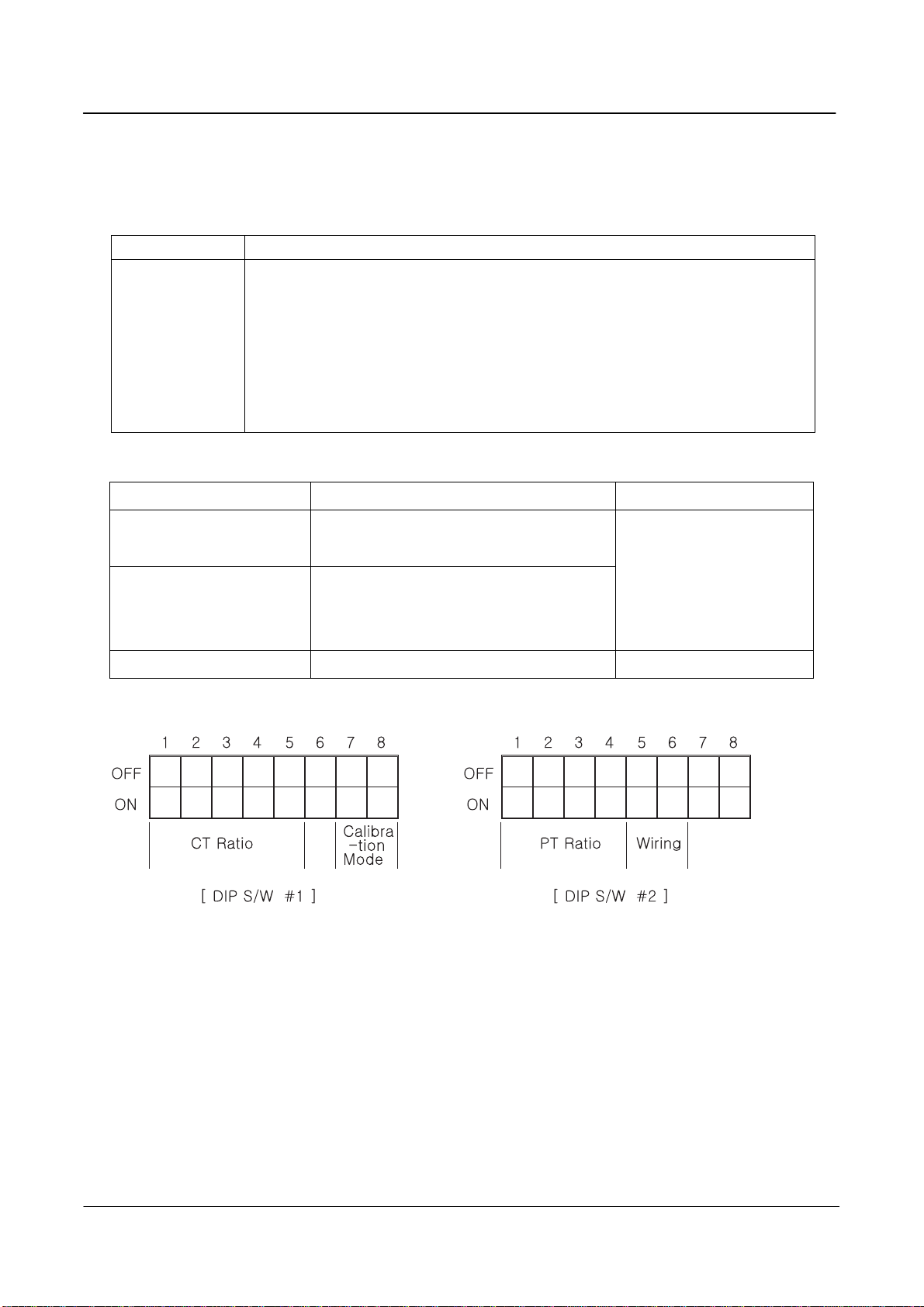
7.2 Setting method of DIP Switch ……………………………………………………………. 23
7.3 Setting communication address number ……………………………………………….. 25
7.4 Affirmation of setting ……………………………………………………………………… 25
7.5 Connection of input circuit ……………………………………………………………….. 25
7.6 External connection drawing …………………………………………………………….. 27
7.7 Cutting dimensions of fixing part ……………………………………………………….. 28
7.8 External view and dimensions …………………………………………………………… 29
8. Communication
8.1 Specification ………………………………………………………….……………………… 29
8.2 Sequence of Events Function ………………………………….…………………………. 30
8.3 Composition of communication system ………………………………………………… 30
9. Maintenance
9.1 A defect management during the test operation ………………………...…………… 31
9.2 Replacement …………………………………………………………………………………. 32
Appendix(Time Table) ………………………………………………………….. 33
CONTENTS

3
GIPAM User Manual
1 Summary
LG Digital Integrated Protection and Measurement device indicates and measures
electricity amount of various kinds such as 3 phases voltage, current, power electricity,
power factor, frequency, zero phase voltage and so on. It also has 6 kinds of
function for the protection relay (OCR, OCGR, OVR, UVR, OVGR, SGR). It can be
applied at 1W2P/3P, 3W3P/4P.
2 Characteristics
1) Compact and Simple
- GIPAM is an assortment of equipments for switchgear panel. It includes panel
meters, protection relays, operating and transffering switchs and lamps in one unit.
- Various types of characteristic curves are provided.
- It makes high reliance of protection by adopting . technology of digitail filter
applied 16bit μ-processor.
2) Self Diagnosis Function
GIPAM detects an error of CPU operation or circuit of signal input immediately and
it indicates caution and reason of error. It also has a data transmission function .
3) An outstanding flexibility
GIPAM corresponds suitably to a change of PT ratio, CT ratio and wirings through
setting DIP Switches.
4) Fault & Event Recording
● 255 Faults and Events can be recorded.( a 10ms aberration)
● It is available to analyze an error of system and a daily or monthly record.

4
GIPAM User Manual
3 Main Features
1) High accuracy measuring function
● 3 Phases Voltage/Current
● Power Active(Watt)/Reactive(Vars)
● Energy Active(Wh)/Reactive(Varh)
● Power Factor
● Frequency
● Zero Phase Voltage(Vo)
2) Multi Functional Relays
● OCR (Overcurrent relay)
● OCGR (Overcurrent ground relay)
● UVR (Under voltage relay)
● OVR (Over voltage relay)
● OVGR (Over voltage ground relay)
● SGR (Sensitive ground relay)
3) Indication Function
● Indicates the status of protection relay and circuit breaker on front LED.
● Displaying status via digital LCD and analog bar graph to offer better visual
effect to customer.
● Error message is indicated on front DOT Matrix LED when error occurs.
4) Communication Function
- All data and information can be transferred to a host computer up to 255 sets
of GIPAM with high speed (250kbps) through internal communication module.

5
GIPAM User Manual
4 External view and System structure
4-1 External view and part name
4-2 System structure

6
GIPAM User Manual
5 Spacification
5-1 Metering
1)Input specification
Contents Rating
Wiring Type 1P2W, 1P3W, 3P3W, 3P4W
Frequency 60Hz
Voltage AC10~132V/AC20~264V
Input
Range
Current 0.2~6A
2) Range of the metering result
Meter Menu Metering Value Displayed Range Accuracy(%) Remarks
Voltage(V) RMS Value LCD: AC10~154000(V)
Bargraph:0 to 120(%) ± 1.0%
Between Phases
Between phase and
Neutral
Current(A) RMS Value
LCD: AC0.2~6000(A)
Bargraph:0 to 120(%) ± 1.0%
Each phase
Zero Phase Voltage(Vo) RMS Value 0~190(V) ± 2.5%
Max. Value back up
Active, Watt Average Value LCD: 0~9999(MW)
Bargraph:0 to 120(%) ± 2.0% Power
Reactive,
Vars Average Value LCD: 0~9999(MVars)
Bargraph:0 to 120(%) ± 2.0%
Active, Wh Accumulated Value 0-999999(MWh) ± 2.0% Energy
Reactive, Varh Accumulated Value 0-999999(MVarh) ± 2.0%
Power Factor, PF Average Value Lead/Lag 0-100(%) ± 2.0%
Frequency(Hz) Average Value 45~65(Hz) ± 0.5%
3) Input/Output Contact
MENU Contents Type Rating
Input
CB-ON
CB-OFF DC110(V) Connected Voltage and Current to origin of signal:
DC110V, 5mA Max
OCR
OCGR
OVR
UVR
OVR
SGR
Alarm
System Error
CB-ON
CB-OFF
Zero Voltage
"a" Contact
Output
REM/LOC "C" Contact
Resitance Load: AC250V, 10A
DC 30V, 10A CosΦ=1.0
Induction Load: AC250V, 7.5A
DC 30V, 5A
CosΦ=0.4, L/R=7ms
Switching Capacity: 2.500VA, 300W

7
GIPAM User Manual
4) Displaying a status of Circuit Breaker and operation
LED Lamp Name Detail
CB-On (Red)
CB-Off (Green)
Local (Yellow)
Remote(Yellow)
Power (Red)
Comm (Red)
Func (Red)
LED lamp will be on when breaker is "on" position.
LED lamp will be on when breaker is "Off" position.
When operator select local control, LED lamp will be turned on.
When operator select remote control, LED lamp will be turned on.
LED lamp will be on during the system is operated.
LED lamp blinks when GIPAM is communicated with host.
When operator select special function mode, LED lamp will be turned on.
5) Setting a metering part
Setting object Detail Location
Metamorphosis Ratio CT Ratio: DIP Switch(#1) 5bit
PT Ratio: DIP Switch(#2) 4bit
CPU Reset
Calibration Mode
Connetion Method
Reset all data of CPU
Set up DIP Switch(#1) by 2bit
Set up DIP Switch(#2) by 2bit
Upper part of main board
Communication Address Set up specific address by 16 bit switch. Main Board
Note) Please do not operate no. 7 and no. 8 of DIP Switch #1.
→ LGIS set up in best condition when it is shipped from the factory. Please do not operate or
change the setting value. In case of reset unwillingly, please refer to appendix.

8
GIPAM User Manual
6) Other specification
Contents
a
il
Voltage
Input burden Current
Under 0.1 VA
Under 1 VA
Voltage DC110[V] (93.5~121V)]
Control Power Current Under 15[W]
Data Backup Over 10 years by adopting NV-RAM.
Operation -10~55℃
Tem
p
erature Storage -25~75℃
Humidity 80% RH(Non-condensing)
Insulated Resistance Over DC500V 10MΩ, Tested part is the same as impulse voltage.
Between electrical circuit ground: AC 2,000V/1min.
Between electrical circuit phase: AC 2,000V/1min.
Power Frequency withstand
Voltage Between electrical circuit terminal: AC 1,000V/1min.
5kV for 1.2×50μ
Lightning Impulse Voltage 3kV for 1.2×50μ
Rated amp.×2 for 3hours
Current Circuit Rated amp.×20 for 2 seconds
Overload
Withstand
Capacity Voltage Circuit Rated volts×1.15 for 3 hours
Applied Standard IEC 60255, KEMC 1120, JEC174C
5-2 Protection
1) INPUT
Contents Detail
Frequency 60Hz
Voltage PT: 110[V], GPT: 190[V]
Input Range
Current CT: 5[A], ZCT:1.5mA

9
GIPAM User Manual
6 Operating
6-1 Measuring Part
6-1-1 Calibration Mode
A calibration mode of metering consists of 2 modes. One is adjusting offset and gain
of A/D converter and the other is selecting the ratings of analog
input signal. (Please do not adjust a calibration mode temporarily. If there are
necessity of adjustment, refer to appendix.)
6-1-2 Measurement display
The measurement result is displayed by pushing the measurement selection key.
Easurement key displays
1) Current
Display panel shows current value of phase “R” at the initial status.
Each phase of current measurement value will be displayed continuously
with the “A” unit by repeating to push the touch switch “A”. (It is possible
to check the type of wiring when operator pushes the Function and F
key at the same time.)
Type of wiring Displayed phase Remark
1P2W
1P3W
3P3W, 3P4W
Measurement value of each phase
R → N → T
R → S → T
FUNC + V : PT Ratio
A : CT Ratio
F : Connection
W : Comm Address
Var : C/B Operatopn
Pf : Display All
Wh : C/B ON Time
Varh : Vo/Vomax

10
GIPAM User Manual
2) Voltage
Each phase of voltage measurement value will be displayed continuously with the “V”
unit by repeating to push the touch switch “V”.
Type of wiring Displayed phase Remark
1P2W
1P3W
3P3W
3P4W
Measurement value of each phase
RN → TN → RT
RS → ST → RT
RN → SN → TN →RS → ST → RT
3) Power
Active power is displayed with “W” unit by pushing touch switch “W” and reactive
power will be displayed with “Var” by pushing touch switch Var.
4) Energy
Active energy is displayed with “WH” unit by pushing touch switch “Wh” and reactive
energy will be displayed with unit “Varh” pushing touch switch Varh.
5) Power Factor
Power factor is displayed by pushing touch switch PF with “%” unit and also
displayed “LEAD” or “LAG”.
6) Frequency
Frequency is displayed by pushing touch switch F with “Hz” unit and it
displays the first decimal place.
6-1-3 Special Function
Pushing the FUNC Switch, it is transferred to special function mode and the switch
lamp is turned on. It shows special function mode continuously during the switch lamp
of FUNC Switch is on. If operator pushes the FUNC Switch again, it will return to
standard mode. If it is changed to special mode, measuring switch function will be
changed and it displays as followings:
1) FUNC+V: It displays PT ratio setting value of DIP Switch.
2) FUNC+A: It displays CT ratio setting value of DIP Switch.
3) FUNC+A: It displays wiring type

11
GIPAM User Manual
4) FUNC+W: It displays a settled own address at telecommunication part of main board.
5) FUNC+Var: It displays the number of operation time of the circuit breaker
which is connected to CB ON input contact.
6) FUNC+PF: It displays all the measured data by the following sequence in a
row(V → A → W → VAR → WH → VARH → F → PF, Voltage/Current: every
phases have been measured.)
7) FUNC+Wh: It displays the let through time(Hour unit) of the CB which is connected
to the CB ON input contact. When the time is over 9999hours, it displays the time
by the bargraph on the 10000 hours unit.
8) FUNC+VARH: It displays Vo with N1 and Vo max. with N2.
6-1-4. CB operation and local or remote control
1) LOCAL: It is the key for the local operation . If press this button, local output
contact will be on and it makes possible to operate C/B on or off by pressing the
keys on the front.
2) Remote: It is the key for the remote control . If press this button, remote output
contact will be on and it can be possible to operate C/B on or off by
telecommunication at host computer.
3) CB ON/OFF: If press the ON/OFF switch, output contact will be conducted during
from 0.5 to 0.6 seconds. It makes operate CB(ON/OFF Operation) when local
operation switch is selected.
6-1-5. Others
1) Clear switch
. The clear switch in the back plate reset the WH & VARH value to “0”
. The users should press the reset button when you first install the system.
2) CPU Reset button
. The CPU reset switch in the back plate clear all the data in the CPU. When you
found the operations of the equipment is unusual, you can press and restart.
3) COMM LED
During the communication with monitoring computer, it is go on and off.

12
GIPAM User Manual
6-1-6. Display for the system error
Error code will be displayed in case of it is out of order. Error code is displayed as
followings :
Error 0: PT ratio setting is wrong.
Error 1: CT ratio setting is wrong.
Error 2: Detect voltage error of analog circuit and input circuit.
Error 3: Detect internal telecommunication error.
Error 4: Detect CPU abnormal operation.
6-2 Protection part
6-2-1 Initialization setting
1) DIP switch setting
Set up a use frequency and an assigned function of relay.
2) Calibration of input amount of energy
Please do not adjust a calibration mode temporarily. If there are
necessity of adjustment, please refer to appendix.)
6-2-2. Operation
1) Display of operating status
- After power is on, DOT-matrix and LCD part will be turned on during
1 second. If displayed [Run…], it means normal operating status.
- It displays system error and fault of relay.
- Function of each key
◆ [SET/RUN] : Changing the normal mode to the setting mode or vise versa.
◆ [CHAR] : It is an effective key at setting mode and makes possible to move
among the setting menu of each really facts.
◆ [▼] : It is effective key at setting mode and it makes possible to decrease the
set data.
◆ [▲] : It is effective key at setting mode and it makes possible to increase the
set data.
◆ [ENT] : It is effective key at setting mode and it saves the corrected data.
◆ [RESET] : It is effective key at Normal mode When remove the
cause of system error and fault, it resets error indication.

13
GIPAM User Manual
2) Protection function setting
Dot Matrix LED displays [Run…] as normal state when control power is supplied to
GIPAM. Press [Set/Run] key to move to setting mode to set following protection
functions.
Note 1> D2, D4, D8 : Definite time delay (t = 2, 4, 8)
2> SI, VI, EI, LI : Standard Inverse, Very Inverse, Extremely Inverse and Long Inverse
time delay curves, respectively
3> XX, AL, TP : Operation mode setting
(XX : no operation, AL : alarm mode, TP : alarm & trip mode)
3) Display of fault status
◆ Fault LED is turned on in case of error detected each factor
of relay. It displays by blinking the value of operation or the factor of operation.
Fault LED of Relay LCD Display Remark
OCR operated Ir (value) Ir, Is, It(Over current occurs on phase R,S or T.)
(Value of Indicator) x 5(A) x CT Ratio →
Operated current of OCR.
OCGR operated I (value) (Value of Indicator) x 5(A) x CT Ratio →
Operated current of OCGR.

14
GIPAM User Manual
OVR operated Ov (value) (Value of Indicator x 110(V) x PT Ratio →
Operated voltage of OVR.
UVR operated Uv (value) (Value of Indicator) x 110(V) x PT Ratio →
Operated Voltage of UVR.
OVGR operated V (value) (Value of Indicator) x 190(V) x GPT Ratio
→ Operated Voltage of OCGR.
SGR operated SGR
◆ If press the [reset] key after removing the cause of fault, a relay will be on operation.
4) Measuring display of protection relay part
◆ If press the [CHAR] key during the [Run..] is displayed at operating mode,
measurement
value will be displayed with the Ir. If repeat to press the [CHAR] key, it displays
measurement value of each contents in a row as followings. But the fact value of
measurement calculated by formula as table.
(Ir → Is → It → I → Ov → Uv → V → Io → Run..)
5) Display of System error
◆ Error code is blinking and displaying when internal trouble occurs. Error codes are
same as followings:
ERR 1 : Detect the analog circuit error of voltage or input circuit.
ERR 2 : Detect damage of back-up data
ERR 3 : Detect obstruction of internal telecommunication(RS-232C)
Contents LCD Display The fact value
Current of Phase “R” Ir (value) Value of indication: 5(A), CT Ratio
Current of Phase “S” Is (value) Value of indication: 5(A), CT Ratio
Current of Phase “T” It (value) Value of indication: 5(A), CT Ratio
Current of Ground Fault I (value) Value of indication: 5(A), CT Ratio
Ov (value) Value of indication: 110(V), PT Ratio
Voltage Uv (value) Value of indication: 110(V), PT Ratio
Zero Phase Voltage V (value) Value of indication: 190(V), GPT Ratio
Zero Phase Current Io (value) Value of indication: 1.5(mA), ZCT Ratio

15
GIPAM User Manual

16
GIPAM User Manual

17
GIPAM User Manual

18
GIPAM User Manual

19
GIPAM User Manual
This manual suits for next models
2
Table of contents
Popular Relay manuals by other brands

Simplex
Simplex 4090-9118 installation instructions

Interlogix
Interlogix ACL800FL-RU2 installation manual

Pilz
Pilz PNOZ X2.1C operating manual

Allen-Bradley
Allen-Bradley Guard master Minotaur MSR312P Quick start guide - Troubleshooting

ABB
ABB CL-LSR Series Instruction leaflet

Siemens
Siemens 3UA50 instructions