LS MTRON KTFM-84S User manual

WARRANTY CONDITIONS
Warranty Coverage :
Warranty Provisions :
▶ Compensation is not paid for physical harm, deadlock, resulting damages or other losses.
Right To Make Design and Product Changes :
It is further understood and agreed that the defect should be immediately reported to the Selling
Dealer. The Selling Dealer will generally perform Warranty repairs or replacements and the
Purchaser shall deliver the LS Mtron Mower to the Dealer's place of business or repair.
The obligation of LS Mtron to the Purchaser under this Warranty is limited to the repair or
replacement of defective parts by an authorized LS Mtron dealer. Repair or replacement in
accordance with this Warranty shall constitute fulfillment of all liabilities of LS Mtron and the
Selling Dealer in respect to LS Mtron Mowers.
LS Mtron Tractor Division, herein referred to as LS Mtron, undertakes to replace or repair any part
of a LS Mower where damage has been proven to be caused by defects in material or
workmanship.
This Warranty is valid for a period of 1 year from the date of the original retail sale. Parts
replaced or repaired under the terms of this Warranty are guaranteed only until the original
warranty expires. Warranty only applies to the original purchaser.
▶ The purchaser shall at all times in the operation of any LS Mtron Product, use those brands
and grades of lubricating oils, lubricants or fuel and spare parts officially approved by LS Mtron.
▶ The LS Mtron Mowers shall have been used in accordance with the procedures specified in the
Operator's Manual. This Warranty does not extend to damage resulting from misapplication,
abuse, misuse, failure to preform maintenance, negligence, fire, accidents or changes or faulty
mounting carried out by the Purchaser. When making a Warranty exchange of parts, the
Purchaser shall compensate LS Mtron for the time that the parts have been used if they have
been exposed to extreme wear.
There are no warranties beyond those which expressly appear herein. Any implied warranty of
merchantability or fitness for a particular purpose is specifically exclude here from.
LS Mtron reserves the right to make changes in the design and other changes in its LS Mtron
Products at any time without incurring any obligation with respect to any product previously
ordered, sold or shipped.
▶ Temporary repairs or additional costs due to the work being performed after normal working
hours will not be compensated.
▶ The above warranty is in lieu of all other warranties on LS Mtron's behalf and neither party
assumes any other liability in connection with LS Mtron's Products.
▶ To obtain warranty service, the Purchaser must (1) report the product defect to an authorized
LS Mtron dealer and request repair within the applicable warranty term and (2) present evidence
of purchase.
▶ The Warranty shall be void if the LS Mtron Mower has been altered or repaired outside of a LS
Mtron dealership or travel of dealer personnel to customer location for Warranty repair. The
customer shall also pay any premium for overtime labor requested by the customer.
LS Mtron's liability under this warranty is subject to the observance by the Purchaser of the
following provisions:
- 1 -

PLEASE NOTE :
Make sure all potential operators of the this equipment review this manual and all safety
messages contained within
This safety symbol indicates important safety messages in this manual. When you see
this symbol, carefully read the message that follows and be alert to the possibility of
personal injury or death.
- 2 -

Table of Contents
▣ Safety Precautions 4
▣ Safety Decals 6
▣ Mower Specifcation 8
▣ Introduction 9
▣ Lubrication and Maintenance 10
▣ Blade Replacement 12
▣ Spare Parts 13
▣ Torque Tightening Chart 14
▣ Parts IIlustrations 15
General Information 15
Finish Mower Assembly 16
Gear Box Assembly 20
Blade Assembly 22
Wheel Assembly 23
Decals 24
▣ Mower Set-Up 25
- 3 -

SAFETY PRECAUTIONS
CHECKS BEFORE USE
▶
▶
ADDING OIL AND INJECTING GREASE
▶
▶
CHECKS BEFORE MOVE FORWARD & BACKWARD
▶Stay clear when the mower is running.
▶Never step on the machine while it is driving and during transport.
▶Move backward at slow speed. Inspect backward and under the mower.
TRANSPORT
▶
▶
▶
CLOTHES & PROTECTIVE EQUIPMENT
▶
▶
shoes.
▶
▶
▶
▶
Check the gearbox oil and grease state.
Belt tension : Maintain to be just tight enough to prevent slipping.
Most tractor and/or Mower equipment accidents can be avoided by following simple safety precautions.
The safety information given in this manual does not replace safety codes, insurance requirements, federal,
state, and local laws. Make sure your machine has the correct equipment required by your local laws and
regulations. Understand that your safety and the safety of other persons are measured by how you service
and operate this Mower.
Know the position and operations of all controls before you try to operate. Make sure you check all controls
in a safe area before starting.
Read this manual completely and thoroughly and make sure you understand all controls. All equipment has
a limit. Make sure you are aware of the stability and Mowing characteristics of this Mower before you begin
o
p
eration.
This safety alert symbol indicates important safety messages in this manual. When you see this
symbol, carefully read the message that follows and be alert to the possibility of personal injury
or death.
SAFETY PRECAUTIONS
LS Mtron grooming mower described in this manual have been designed to mow lawn only.
The operator must wear the suitable clothing and personal protective equipment at while working on the
mower or running it.
Use safety gloves & safety glasses or masks, to protect the operator's eyes and face. Wear safety
CHECKS BEFORE START-UP
Make sure that the mower and the tractor are certainly connected.
LS Mtron grooming mower is designed to be combined with 2HP~40HP tractors equipped with a
category-1 3point link system a 540-rpm clockwise PTO.
When adding the oil, please stop the tractor's engine.
Often injecting grease at BLADE ASSMBLY #1, #2, #3 part and WHEE ASSEMBLY part.
Without using proper hinge pins & related lynch pins.
Always disengage the PTO for transport. Avoid that the mover touches the tractor when raised and that
the tractor lower arms are stabilized and do not touch the inside of the tires.
Check that the PTO does not touch the front of the mower deck in the raised position.
Travel at a safe speed, especially on rough ground. Allow adequate room for vehicles to pass when
traveling on the road.
4

SAFETY PRECAUTIONS
▶
▶
▶
▶
▶
▶
▶
▶
▶
▶
▶
▶
▶
▶
SAFETY PRECAUTIONS
Before replacing the blades, turn the tractor engine off, pull the parking brake, disengage the power
take off, rise the mower using the tractor lift, and install supports to prevent accidental dropping of the
machine.
MOWING
Clear the mowing area of debris BEFORE mowing, especially objects that may be thrown and cause
harm. Dry lawn cuts easier, requires less power and is likely to bunch and plug the mower. If the lawn is
taller than about 8", consider mowing twice proper adjustments.
Do not operate the mower if all the safety requirements are not in place.
Lower mower and start the PTO. Lower to the ground and increase the PTO rpm.
Wear work clothes or other comfortable apparel. Avoid baggy clothes or clothes with long sleeves to
prevent being grabbed by turning or mowing components.
Move forward at slow speed. Inspect the work and consider marking mowing height adjustments by
moving the washers on top of the wheels.
Safety operation
-Do not place your hands, inside the machine when it is running.
-Do not use the mower to transport people or objects when it is running or during transport.
-When rising the mower, slow down PTO speed 20% of normal and only raise as much as is
needed to have the proper clearance. Increases the life of the PTO.
-Mower clogged. Remove material. If it is too wet, wait for grass or mud to dry.
-Do not remove safety cover & safety equipment. If you want to remove or clean it, turn the
tractor engine off first.
-Keep hands, feet and clothing away from attachment when mower is running.
-Do not use the mower to transport a load.
-When the mower is running and working, stay at a safe distance from mower.
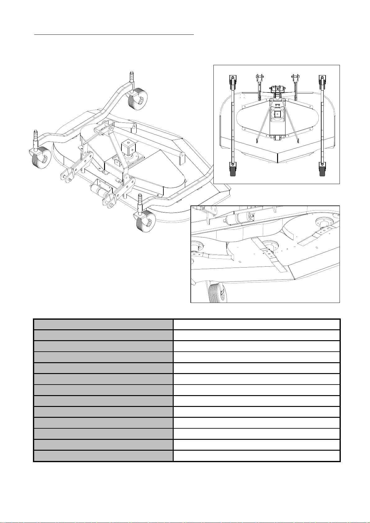
INSPECTION ITEMS
-Make sure that the tractor drawbar does not interfere with either hooking up the mower or running
the PTO.The tractor top link needs to be easily adjustable in length. Position the mower behind
tractor on a level surface. Make sure all lift
p
ins and related l
y
nch
p
ins are in
p
lace.
Do not clean, lubricate, repair or adjust any components when the engine is running or the equipment is
For height adjustment, stop the PTO completely, cut off the engine, remove the lynch pins in the wheel
Belt tension :
-Maintain to be just tight enough to prevent slipping.
-To adjust, turn bolt in front of the gearbox. Belts that too height will lead to premature failure and
may cause a safety hazard.
GENERAL NORMS.
Before starting, running or servicing the machine, do not drink alcoholic beverages, take drugs or any
other substances which ma
y
effect the o
p
erator or service
p
erson's abilit
y
.
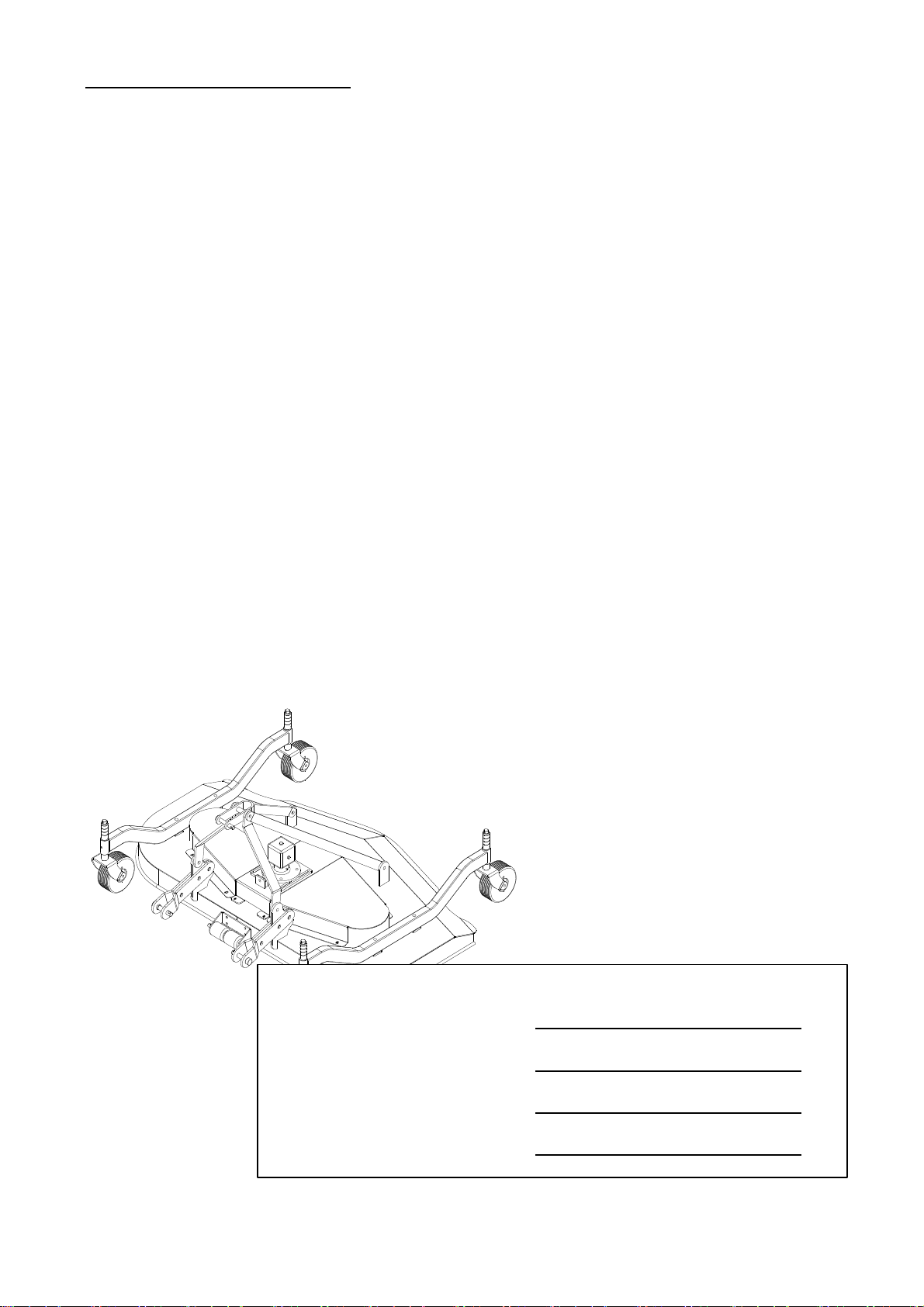
Hooking up to the tractor
-Nobody is standing between the tractor and the mower.
-Make sure that the engine is off, the power take off disengaged and the handbrake engaged when
carr
y
in
g
out when connectin
g
the mower to the tractor.
-Make sure that the tractor PTO shaft and the mower input shaft are connected.
Proper operating, service and adjustment is the key to machine performance and long life. Inspect
frequently for loose bolts, proper belt tension, blade sharpness , ect.
All hardware & guides in place and tight, especially that the blade bolts are tight.
5

SAFETY DECALS
Safety Decal Loacations
Care of Safety Decals.
▶ Keep safety decals clean and free of obstructing material.
▶ Clean safety decals with soap and water and dry with a soft cloth.
▶ Mount new safety decals by applying on a clean dry surface
and pressing air bubbles to outside edges.
▶ Replace damaged or missing safety decals with new decals
from your LS Mtron Dealer.
▶ If a component with a safety decal(s) affixed is replaced
with a new part, make sure new safety decal(s) are attached
in the same location(s) as the replaced components.
3101E-00111 3102E-00018
3102E-00022 3102E-00019
3102E-00006
3102E-00013 3102E-00020 3102E-00063
- 6 -

SAFETY DECALS
3104E-00010
3102E-00062
3102E-000613102E-00021
- 7 -

MOWER SPECIFICATION
Mower Model KTFM-84S
Cutting width 84"
Overall Width 86"
Discharge Rear discharge
Weight, Machine 728 Lbs
Max. PTO-hp Not to exceed 60 HP
Min. PTO-hp 25hp
Cutting Height 3/4" - 4 3/4"
Deck Material 3/8"
Blades Sizes 2 3/8" x 1/4" x 28 3/4"
Blade Overlap 1 3/16"
Blade RPM 2,160
Hitch Cat-1
- 8 -

INTRODUCTION
▶ Important
▶ Warranty Registration
▶ Serial Number and Location
The purpose of this manual is to assist you in maintaining and operating your Mower.
Read it carefully, it furnishes information and instructions that will help you achieve years of
dependable performance.
Some information may be general in nature due to unknown and varying conditions. However,
through experience and these instructions, you should be able to develop operating procedures
suitable to your particular situation.
"Right" and "Left" as used throughout this manual are determined by facing the direction the
machine will travel when in use.
The photos, illustrations and data used in this manual are current at the time of printing, but due
to possible in-line production changes, your machine may vary slightly in detail. The
manufacturer reserves the right to redesign the machine as may be necessary without
The serial number is im
p
ortant information about the machine and it ma
y
be necessar
y
to know it
before obtaining the correct replacement part. The serial number plate is located on the LH(left
hand) inside of front area of boom. The serial number should be recorded on the Delivery and
Registration form and also below for your reference.
The Delivery and Warranty Registration forms must be filled out and signed to validate your
warranty protection. The items on the form under "I hereby Acknowledge" should be read and
understood. The terms and conditions of the warranty on this machine are specified in the front
Illustrations used in this manual may not show all safety equipment that is recommended to
ensure safe operation of tractor and Mower. Refer to the Safety Precautions section of this
manual for information concerning safety. consult your dealer for further information.
FINISH MOWER SERIAL NUMBER
DATE PURCHASED
DEALER NAME
AND TELEPHONE NUMBERᆥ
Finish mower Serial Number Information
- 9 -

LUBRICATION AND MAINTENANCE
▶
※NOTE
Gear box Oil
• Grease all “GREASE" points daily(10 hours). Refer to Tractor Operator's Manual for lubricant
recommendations.
-After the first 50 working hours and, later, every 800 working hours, replace the oil in the gear box.
Use oil SAE EP 80W90
Check the tractor hydraulic system as outlined in the Tractor Operator's Manual.
• Do not operate the Mower if the fittings are leaking or if the hoses are damaged.
A sudden line burst could cause the mower to drop suddenly, causing damage to the tractor or
Mower or injury to personnel.
• Operate the Mower from the tractor seat only.
• Do net stand under a raised Mower.
Accidental movement of control lever or leak in hydraulic system could cause mower to drop,
causing severe injury.
WARNING
• When checking Gear box oil level, the mower should be on the ground horizontaly.
• Do not perform and service or maintenance Operations with mower raised off the ground.
CAUTION
Important
Lower the mower to the ground to performing any service or maintenance operations on the tractor.
- 10 -

LUBRICATION AND MAINTENANCE
Oil
Grease
Oil Lever gage
Oil Drain Hole
Grease
Grease
Grease
ITEM SERVICE SERVICE INTERVAL
Gear box Oil Level Check Daily/10 hours
Gear box Oil Lubricate Daily/10 hours
Pulley Ass'y Lubricate Daily/10 hours
Tire hinge Check Daily/10 hours
Belt tension Check Daily/10 hours
All the hardwares Check visually and Re-
Torque Daily/10 hours
- 11 -

BLADE REPLACEMENT
For proper mower operation, frequently check the lawn mower blades: make sure that they are sharp and
perfectly anchored by means of the bolts. Follow the procedure below to replace the blades.
- Adopt all measures to prevent accidental machine start up.
- Place the equipment on sturdy supports.
- Remove the screws anchoring the blades as shown in
figure; remove the old blades and install the new ones.
WARNING
Before replacing the blades, turn the tractor
engine off, pull the parking brake, disengage the
power take off, raise the mower using the tractor lift,
and install supports to prevent accidental dropping
of the machine.
- 12 -

SPARE PARTS
Always use original LS Mtron spare parts for the best lawn mower performance.
For spare parts requests please refer to the Part Illustrations.
The spare parts can be ordered from your LS Mtron dealer. The following data must always be specified:
- Equipment type and width.
- Part number of the requested component.
- Description of the part and requested quantity.
- Requested type of transport. Should this information not be provided, your LS Mtron dealer shall not be
responsible for delays caused by circumstances beyond their control. The owner shall be responsible for
any transport charges.
- 13 -

TORQUE TIGHTENING CHART
INCH HARDWARE
SAE SERIES
TORQUE
CHART
lbs-ft N-m lbs-ft N-m lbs-ft N-m
1/4" 7/16" 6 8 10 13 14 18
5/16" 1/2" 12 17 19 26 27 37
3/8" 9/16" 23 31 35 47 49 67
7/16" 5/8" 36 48 55 75 78 106
1/2" 3/4" 55 75 85 115 120 163
9/16" 13/16" 78 106 121 164 171 232
5/8" 15/16" 110 149 170 230 240 325
3/4" 1-1/8" 192 261 297 403 420 569
7/8" 1-5/16" 306 416 474 642 669 907
1" 1-1/2" 467 634 722 979 1020 1383
METRIC SERIES
TORQUE
CHART
Always tighten hardware to these values unless a different torque value or tightening procedure is listed
for a specific application.
Fasteners must always be replaced with the same grade as specified in the manual parts list.
Always use the proper tool for tightening hardware : SAE or SAE hardware and Metric for metric hardware.
Make sure fastener threads are clean and you start thread engagement properly.
MINIMUM HARDWARE TIGHTENING TORQUES
IN FOOT POUNDS (NEWTON-METERS) FOR NORMAL ASSEMBLY APPLICATIONS
METRIC HARDWARE
Wrench
Size
SAE Grade 2
(No Dashes)
SAE Grade 5
(3 Radial Dashes)
SAE Grade 8
(6 radial Dashes)
Metric
Grade 8.8
MARKING ON HEAD
SAE 2 SAE 5 SAE 8
Diameter
(Inches)
Metric
Grade 10.9
SAE Bolt Head
Identification
Metric Bolt Head
Identification
N-m lbs-ft N-m lbs-ft N-m lbs-ft N-m lbs-ft
6 x 1.0 10mm 8 6 11 8 8 6 11 8 6 x 1.0
8 x 1.25 13mm 20 15 27 20 21 16 29 22 8 x 1.0
10 x 1.5 16mm 39 29 54 40 41 30 57 42 10 x 1.25
12 x 1.75 18mm 68 50 94 70 75 55 103 76 12 x 1.25
14 x 2.0 21mm 109 80 151 111 116 87 163 120 14 x 1.5
16 x 2.0 24mm 169 125 234 173 181 133 250 184 16 x 1.5
18 x 2.5 27mm 234 172 323 239 263 194 363 268 18 x 1.5
20 x 2.5 30mm 330 244 457 337 367 270 507 374 20 x 1.5
22 x 2.5 34mm 451 332 623 460 495 365 684 505 22 x 1.5
24 x 3.0 36mm 571 421 790 583 623 459 861 635 24 x 2.0
30 x 3.0 46mm 1175 867 1626 1199 1258 928 1740 1283 30 x 2.0
Diameter &
Thread Pitch
(Millimeters)
Metric 10.9 Metric 8.8 Metric 10.9
FINE THREAD
MARKING ON HEAD MARKING ON HEAD
Diameter &
Thread Pitch
(Millimeters)
Wrench
Size
COARSE THREAD
Metric 8.8
- 14 -

PART ILLUSTRATIONS
GENERAL INFORMATION
Illustrations
Directional Reference
Part Order
Istructions
▶ GROUP NAME
: Detail classiflcation name for parts.
▶ SECTION NAME
:Classiflcation name for parts.
▶ COMPONENTS
: The components of an assembly are identifled by a bracket.
▶ NO.
: Reference numbers are assiqned to parts in the figure.
INTERCHANGEABILITY
: Indicates the interchangeabillty of parts due to design change
★ Due to our policy of continuously improving products, The information contained herein is
subject to change withour notice
The individual parts in their normal relationship to each other. Reference numbers are used in the
illustrations. These numbers correspond to those in the "Number" column and are followed by
the quantity required and description.
"Right hand" and "left hand" sides are determined by standing at the rear of the unit and facing
in the direction of forward travel.
Orders must give the complete description, correct part number, the total amount required, the
product model, all the necessary serial numbers, the method of shipment and the shipping
address.
Indicates that a new part can be used instead of an old part when you
order this part, plese order new part.
indicates that either parts can be used.
indicates that either parts can not be used.
~4265-99999
5265-00001~
indicates that a part has a serial number break.
When you order this part, please order a part according to the serial
number of the Loader.
- 15 -

FINISH MOWER ASSEMBLY
- 16 -

FINISH MOWER ASSEMBLY
REF.NO LS PART.NO PART.NO DESCRIPTION QTY I.C SERIAL OR DATE
1 40284510 FMN84-00100-01 84" Main deck W.A. 1
2 40287447 FMN84-00200-02 84" Main cover W.A. 2 2013.02.22~
FMN84-00200-01 84" Main cover W.A. 2
FMN84-CP300 121114081~121114120
FMN84-00300
4 40284513 FMN84-00400 Upper front arm W.A. 1
5 40284514 FMN84-01000-02 Spindle Ass'y 3
40287448 FMN84-01000-04 Spindle Ass'y 3 2013.02.22~
6 40284516 FMN84-02000 Wheel Ass'y 4
40287450 FMN84-02000-01 Wheel Ass'y 4 2013.02.22~
7 40284517 FMN84-03000-02 Gear box Ass'y 1
40287452 FMN84-03000-04 Gear box Ass'y 1 2013.02.22~
8 40284504 FMN84-00001 Upper rear arm 2
940284505 FMN84-00002 Low arm L/H 2
10 40284506 FMN84-00003 Low arm R/H 2
11 40284507 FMN84-00004 Grease terminal cover 1
12 40284508 FMN84-00005 Low arm boss, ∅25 6
13 40284549 FMT84-02002 boss, ∅34 4
14 40255447 TM430-Z0001 Roller 2
15 40284532 FMT84-00004-01 Roller bracket 1
16 40284509 FMN84-00007 Top link 1
17 40284534 FMT84-00007 Top link boss 1
18 40284535 FMT84-00008 Height boss 30 4
19 40284536 FMT84-00009 Height boss 20 12
20 40284537 FMT84-00010 Height boss 10 4
21 40284538 FMT84-00011-01 Low hitch pin 2
22 40284539 FMT84-00012 Top link pin 1
23 40284540 FMT84-00013 Roller shaft 1
24 40284541 FMT84-00014 Roller shaft socket 2
25 40284542 FMT84-00015-01 Single pulley 2
40287454 FMT84-00015-02 Single pulley 2 2013.02.22~
26 40284543 FMT84-00016-01 Double pulley 1
40287455 FMT84-00016-02 Double pulley 1 2013.02.22~
27 40284545 FMT84-00018 Drive shaft 1
28 40284522 FMNCD-00001 PTO Cap 1
3 2Tire frame W.A.40284512
- 17 -

FINISH MOWER ASSEMBLY
- 18 -

FINISH MOWER ASSEMBLY
REF.NO LS PART.NO PART.NO DESCRIPTION QTY I.C SERIAL OR DATE
1 40248354 1012N-M0803-20 Wing screw, M8-P1.25-20L 8
2 40230889 1012S-M0803-25 Sem's Bolt-HT, M8-1.25-25L 2
3 40283967 10191-M1004-25 Hex. Bolt-HT, M10-P1.5-25L 4
4 40230892 10191-M1205-30 Hex. Bolt-HT, M12-P1.75-30L 16
5 40283970 10191-M1606-45 Hex. Bolt-HT, M16-P2.0-45L 4
6 40283971 10191-M1606-C0 Hex. Bolt-HT, M16-P2.0-120L 4
7 40283972 10191-M1807-70 Hex. Bolt-HT, M18-P2.5-70L 6
8 40283973 10191-M1807-G0 Hex. Bolt-HT, M18-P2.5-160L 1
9 40228641 10316-M1000 Washer-Spring, M10 4
10 40228642 10316-M1200 Washer-Spring, M12 16
11 40228644 10316-M1600 Washer-Spring, M16 8
12 40230613 10316-M1800 Washer-Spring, M18 6
13 40228646 10321-M0800 Washer-Plain, M8 8
14 40228647 10321-M1000 Washer-Plain, M10 4
15 40228648 10321-M1200 Washer-Plain, M12 8
16 40228650 10321-M1600 Washer-Plain, M16 4
17 40283976 10321-M1800 Washer-Plain, M18 14
18 40284257 10321-M2500 Washer-Plain, M25 3
19 40228635 1021N-M1205 Nut-Self Locking, M12-P1.75 4
20 40228638 10261-M1606 Hex. Nut, M16-P2.0 4
21 40283975 10261-M1807 Hex. Nut, M18-P2.5 6
22 40283974 1021N-M1807 Nut-Self Locking, M18-P2.5 1
23 40230611 1021N-M2404 Nut-Self Locking, M24-P1.5 3
24 40255422 14041-03040 Cotter pin, ∅3-40L 2
25 40255421 14021-06000 Pin-Ring, ∅64
26 40283977 14051-10070 Pin-Ring, ∅10 3
27 40284529 FMT0Z-0B084 V-Belt, B-Type 84" 2
28 40284524 FMT0Z-00003 Grease terminal, PT 1/8" 3
29 40284525 FMT0Z-00004 Hose-grease, 1/8" 1.8m 1
30 40284526 FMT0Z-00005 Hose tie 6
31 40228707 802G0-T1900 Nipple-Grease, PT 1/8" 7
32 40283988 802G0-T1901-00 Nipple-Grease, PT 1/8" 3
33 40283964 1012P-00400-25 Screw, ∅4.2-25L 3
34 40283963 1012P-00400-07 Screw, ∅4.2-7L 6
35 40284544 FMT84-00017 Key 3
- 19 -

GEAR BOX ASSEMBLY
- 20 -
Table of contents