DALI Display
Control Device
Content
1. DALI Display - General DALI Features .............................................................................................. 2
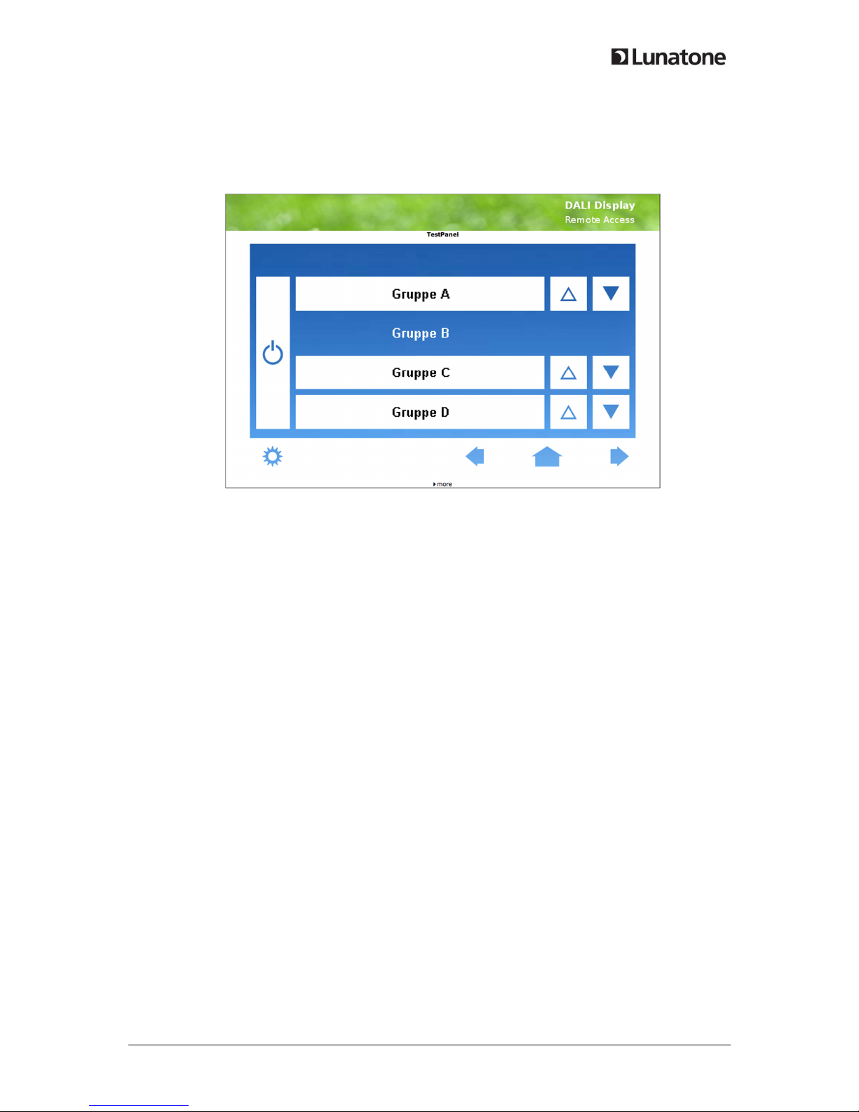
2. Basic Operation Modes ................................................................................................................... 3
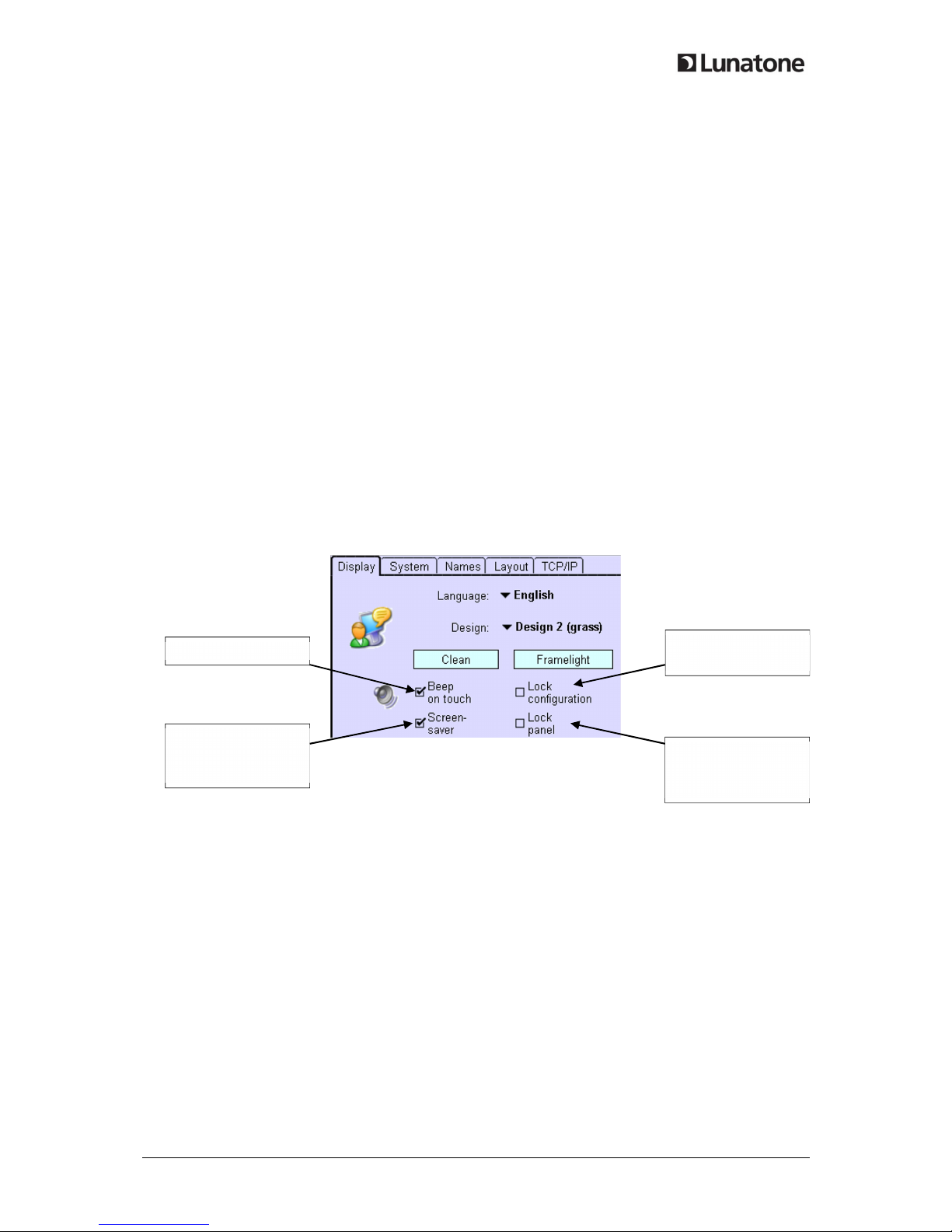
3. Designs ............................................................................................................................................ 5
4. Screen Saver Image and Password Protection ................................................................................ 7
5. Addressing / Grouping ..................................................................................................................... 8
6. Et ernet – Remote Control ............................................................................................................. 9
7. System Update .............................................................................................................................. 10
1. DALI Display - General DALI Features
T e DALI Display as connectors for two DALI lines (DALI A, DALI B). T is allows installing up to 128
DALI ballasts.
Please note t at t e DALI Display does not provide t e bus power for t e DALI bus. A separate DALI
PS needs to be installed on every used DALI bus to provide t e necessary bus power.
Lig t control commands are sent based on DALI Scenes and Groups and are sent to bot DALI lines
simultaneously. Scenes are sent Broadcast, Group commands only to an individual DALI group.
T ere are 16 Scenes and 16 Groups available for bot DALI busses:
Number of DALI addresses: 128
Number of DALI Groups: 16
Number of DALI Scenes: 16
DALI Commands received on DALI line A are mirrored to DALI line B, t is means t at controls
connected on DALI A can also control ballasts on DALI B.
Commands received on DALI B are not mirrored to DALI A, t is allows to install controls t at only
affect one of t e two DALI busses.