manuals.online logo
Brands
  1. Home
  2. •
  3. Brands
  4. •
  5. Lux Products
  6. •
  7. Thermostat
  8. •
  9. Lux Products Ultra 1000 User manual

Lux Products Ultra 1000 User manual

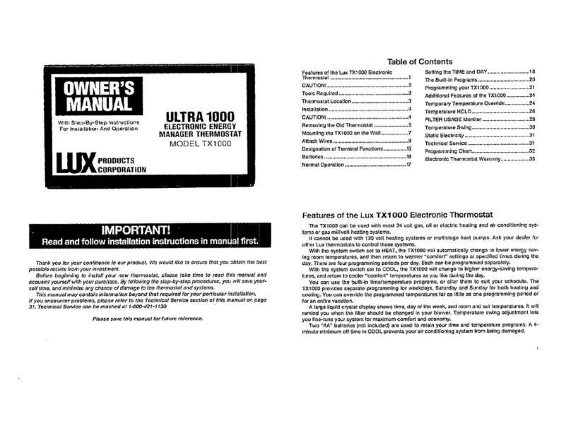
OWNER’S
MANUAL
ULTRA
1000
ELECTRONIC
ENERGY
MANAGER
THERMOSTAT
MODEL
TX1000
With
Step-By-Step
Instructions
For
Installation
And
Operation
PRODUCTS
CORPORATION
IMPORTANT!
|
|
|
|
Read
and
follow
installation
instructions
in
manual
first,
Thank
you
for
your
confidence
in
our
product.
We
would
like
to
ensure
that
you
obtain
the
best
possible
results
from
your
investment.
Before
beginning
to
install
your
new
thermostat,
please
take
time
to
read
this
manual
and
acquaint
yourself
with
your
purchase.
By
following
the
step-by-step
procedures,
you
will
save
your-
self
time,
and
minimize
any
chance
of
damage
to
the
thermostat
and
systems.
This
manual
may
contain
information
beyond
that
required
for
your
particular
installation,
If
you
encounter
problems,
please
refer
to
the
Technical
Service
section
of
this
manual
on
page
31.
Technical
Service
can
be
reached
at
1-800-421-1130,
`
Please
save
this
manual
for
future
reference.
Table
of
Contents
Features
of
the
Lux
TX1000
Electronic
Setting
the
TIME
and
DAY..
Thermostat
The
Built-In
Programs.....
CAUTION!
Programming
your
TX1000......
Tools
Required.
Additional
Features
of
the
TX1000.
Thermostat
Location
Temporary
Temperature
Override...
Installatio
Temperature
HOLD.
CAUTION!
FILTER
USAGE
Manito
Removing
the
Old
Thermostat
....
Temperature
Swing...
Mounting
the
TX1000
on
the
Wali.
Static
Electricity
Attach
Wires
ren
Technical
Servic!
Designation
of
Terminal
Functions
Programming
Chart
Batteries
Electronic
Thermostat
Warranty......
Normal
Operation
....
Features
of
the
Lux
TX1000
Electronic
Thermostat
The
TX1000
can
be
used
with
most
24
voit
gas,
oil
or
electric
heating
and
air
conditioning
sys-
tems
or
gas
millivolt
heating
systems.
It
cannot
be
used
with
120
volt
healing
systems
or
multistage
heat
pumps,
Ask
your
dealer
for
other
Lux
thermostats
to
control
those
systems.
With
tha
system
switch
set
to
HEAT,
the
TX1000
will
automatically
change
to
lower
energy
sav-
ing
room
temperatures,
and
then
return
to
warmer
“comfort”
settings
al
specified
times
during
the
day.
There
are
four
programming
periods
per
day.
Each
can
be
programmed
separately.
With
the
system
switch
set
to
COOL,
the
TX1000
will
change
to
higher
energy-saving
tempera-
tures,
and
return
ta
cooler
"comfort"
temperatures
as
you
like
during
the
day.
You
can
use
the
hullt-in
time/tamperature
programs,
or
alter
them
to
suit
your
schedule.
The
TX1000
provides
separate
programming
for
weekdays,
Saturday
and
Sunday
for
both
heating
and
cooling.
You
can
override
the
programmed
temperatures
for
as
little
as
ane
programming
period
or
for
an
entire
vacation.
A
large
liquid
crystal
display
shows
time,
day
of
ihe
week,
and
room
and
set
temperatures,
It
will
remind
you
when
the
filler
should
be
changed
in
your
blower.
Temperature
swing
adjustment
Iets
you
fine-tune
your
system
for
maximum
comfort
and
economy.
Two
"AA"
batteries
(not
included)
are
used
1o
retain
your
time
and
temperature
programs.
A
4-
minute
minimum
off
iims
in
COOL
prevents
your
alr
conditioning
system
trom
being
damaged.
CAUTION!
4.
Your
thermostat
is
a
precision
instrument.
Please handle
it
with
care.
2.
Turn
ой
electricity
to
the
appliance
before
installing
or
servicing
thermostat
or
any
part
of
the
system.
Do
not
turn
electricity
back
on
until
work
is
completed.
3.
Do
not
short
(jumper)
across
electric
terminals
at
control
оп
furnace
ar
air
conditioner
to
test
system.
This
will
damage
ihermostat
and
yoid
your
warranty.
4,
All
wiring
must
contorm
to
local
codes
and
ordinances.
5,
This
thermostat
is
designed
for
use
with
24
vail
and
millivolt
systems.
The
thermostat
should
be
limited
to
a
maximum
of
1.0
amps;
higher
amperage
may
cause
damage
to
the
thermostat.
A
you
are
in
doubt,
call
your
utility
company.
Tools
Required
Phillips
screwdriver
(small)
Drill
with
3/16"
Bit
Thermostat
Location
For
accurate
temperature
control
and
comfort,
correct
location
is
very
important.
On
new
installations,
the
guidelines
listed
below
should
be
followed
as
closely
as
possible.
When
replacing
an
old
thermostat,
install
the
new
one
in
the
same
location
unless
these
conditions
sug-
gest
otherwise,
1.
Locate
ihe
thermostat
on
an
inside
wall
about
five
feet
abave
the
floor,
where
it
is
easy
to
install
and
adjust.
It
should
be
in
a
room
that
is
used
often,
such
as
a
family
room.
2.
Do
not
install
it
where
there
are
unusual
healing
conditions,
such
as
direct
sunlight,
clase
to
а
lamp,
radio,
television,
radiator,
register,
near
a
fireplace,
or
other
heat
producing
appliance.
Also
check
for
hot
water
pipes
within
the
wall,
or
a
stove
on
other
side
of
wall.
3.
Do
not
locate
in
unusual
cooling
conditions,
such
as
an
outside
wall,
or
one
separating
ап
unheated
room,
or
in
drafls
from
stairwells,
doors,
or
windows.
4,
Do
not
locate
in a
damp
area,
This
can
shorten
thermostat
life
due
to
corrosion.
5.
Do
not
locate
where
air
circulation
is
poar,
suck
as
in
a
corner,
alcove,
or
behind
an
open
door.
6.
Do
not
install
until
all
construction
work
and
painting
have
been
completed.
7.
This
thermostat
does
not
require
leveling,
ехсорі
for
appearance
sake.
installation
Please
read
all
instructions
carefully.
CAUTION!
Before
beginning,
disconnect
power
supply
to
avoid
electrical
shock,
and
to
prevent
damage
to
the
furnace,
air
conditioner,
and
thermostat.
This
can
be
done
at
fuse
box,
circuit
breaker,
or
at
appliance.
FIGURE
1
4
Removing
the
Old
Thermostat
With
the
electricity
to
the
furnace
and
air
conditioner
turned
OFF,
proceed
with
the
following
directions.
CAUTION!
Do
not
remove
any
wiring
fram
existing
Ihermostat
before
reading
instructions
carefully.
Wires
must
be
labeled
before
removing
them.
W
Remove
cover
from
old
thermostat.
Most
are
snap-on
types
and
simply
puli
off,
Some
have
locking
screws
on
the
Side.
These
must
be
loosened,
S
IMPORTANT:
When
removing
wires
from
Iheir
terminais,
note
letters
printed
near
terminals.
Ignore
the
coler
of
the
Wires,
since
these
may
not
comply
with
the
standard.
Attach
corresponding
labels,
enclosed,
to
each
wire
for
identification.
Remove
and
label
wires
one
at
a
time.
Make
sure
the
wires
do
not
fall
back
inside
the
wall.
E
Loosen
all
screws
оп
the
old
thermostat
and
remove
it
Irom
the
wall.
FIGURE
2
9
Strip
Insulation
3/8"
(rom
wire
ends
and
ciean
off
any
corrasian.
FIGURE
3
M
Fill
wall
opening
with
non-combustible
insulation
to
pre-
vent
drafts
from
affecting
thermostat.
FIGURE
4
[3
Mounting
the
TX1000
on
the
Wall
Removing
the
Cover
п
Aemove
body
from
base
by
pressing
button
on
bottom
of
thermostat
and
tilting
out
and
up.
Be
caraful
not
to
drop
ihe
body.
Do
not
disturb
Inner
electronic
parts.
Leave
the
front
doar
closed
while
the
body
is
removed
fram
the
pase,
the
base
to
a
so
IMPORTANT:
if
you
are
mounting
s
material
like
plasterboard
or
using
the old
mounting
holes,
the
screws
may
not
hold.
Оп!
a
3/16"
hole
at
each
screw
location,
and
insert
plastic
anchors
provided.
Then
mount
the
base
as
described
below.
|
‚
ing
trough
п
Hold
base
against
the
wall,
with
the
wires
comin
wherever
it
is
convenient
for
wiring.
Route
wiras
to
below
the
lerminal
block.
Position
base
for
best
appearance,
to
hide
any
marks
from
the
old
thermostat.
Attach
base
to
wall
with
the
two
screws
provided.
FIGURE
6
Attach
Wires
ROUTE
WIRES
TO
TERMINAL
BLOCK
CAUTION!
Do
not
allow
wires
to
touch
each
other
or
parts
on
thermo-
stat,
Wires
must
be
routed
to
below
the
terminal
block,
or
they
will
hit
parts
on
the
cover.
Make
sure
ali
7
electrical
terminal
screws
are
tightened
securely.
Find
the
wiring
chart
that
best
describes
the
number
of
wires
FIGURE
7
and
their
labels.
Connect
the
wires
as
follows;
{А)
For
а
haating
system
using
two
wires:
*
Connect
the
wire
marked
5,
A,
RH,
or
V
to
the
AH
terminal.
*
Connect
the
wire
marked
W,
Н,
or
4
to
the
W
terminal.
(B)
For
a
heating
system
using
three
wires:
*
Connect
the
wire
marked
5,
R,
RH,
or
V
to
the
RH
terminal.
+
Connect
the
wire
marked
W
or
4
te
the
W
terminal,
*
Connect
the
wire
marked
G
or
F
іс
the
G
terminal.
*
Ione
wire
Is
marked
B
(optional
with
some
thermostats),
see
chart
on
page
10.
(С)
For
a
heating
and
coollng
system
using
four
wires,
use
four
of
the
following:
Be
sure
the
jumper
is
installed
between
RH
and AC,
*
Connect
the
wire
marked
W
to
the
W
terminal,
*
Connect
lhe
wire
marked
RC,
R,
or
V
to
ifte
AH
terminal.
*
Connect
the
wire
marked
Y,
or
C
to
the
Y
terminal.
*
Connect
the
wire
marked
G,
ar
F
to
the
G
terminal,
*
Connect
the
wire
marked
B,
or
О
(optional
with
some
thermostats)
to
the
B
or
О
terminal
respectively.
(0)
For
heating/cooling
system
using
five
wires,
use
five
of
the
following:
For
two
transformer
system,
remove
jumper
between
RH
and
RC.
*
Conneet
the
wire
marked
W
to
the
W
terminal.
*
Connect
the
wire
marked
RC,
Н,
or
V
ta
the
AC
terminal.
*
Connect
the
wire
marked
Y,
or
C
to
the
Y
terminal.
*
Connect
the
wire
marked
G,
or
F
to
the
G
terminal,
*
Connect
the
wire
marked
B,
or
O
(optional
with
some
thermostats}
to
the
B
or
O
terminal
respectively.
*
Connect
the
wire
marked
A,
RH,
or
4
to
the
RH
terminal.
NOTE!
If
you
have
an
electric
system
and
after
installation
the
blower
does
not
operate,
find
the
electric/gas
heat
selector
on
the
back
ef
the
body.
Move
the
selector
to
the
ELEC
postition.
TYPICAL
HOOKUP
FOR
2-WIRE
24V
HEATING
SYSTEM
AND
MILLIVOLT
SYSTEM
TYPICAL
HOOKUP
FOR
3-WIRE
HEAT
SYSTEM
IF
THIRD
WIRE
15
FAN
WIRE
Y
W
RH
B O
RC
Y
W
RH
B
O
RC
ообооф
Wiring
Charts
Heating
Systems
Pravious
Thermostat
Connect
to
TX
$000
q
System
Terminal
Marking
Terminal
Wire
То
2
Wire
5,
A,
RH,
V,
ВС
RH
Transtormer
a
(includes
2
wire
hydronic)
М,Н,
4
wW
Healing
Valve
=
Б,
A.
REL
V
RH
чтапа!бттпег
—|
Q
3
Wire
Wis
№
Heating
Valve.
B
Tape
Of
р
c
4
Tape
ОЙ"
“
[3
Wire
А
Transformer
(One
Wire
Heating
Valve
is
"F"
or
"G")
Fan
Relay
"replacing
Honeywell
T-11
tnermastat,
tape
ol
“R
wire.
Connect
ae
ттан
“В”
to
"RH"
terminat.
"A
regtacing
a
Honeywell
thermostat
with
a
clock
wire
(G),
tape
off
"C"
wiro.
Cooling
Systems
Previous
Thermostat
Connect
to
TX1000
System
Terminal
Marking
Terminal
Wire
To
RC,
R,
V
RC
Transformer,
2Wire
Ү.С
|
ү
Cooling
Relay
Heating/Cooling
Systems
TYPICAL
COOLING
AND
HEATING
SYSTEM
24
VAC
TRANSFORMER
OR
THERMOPILE.
FIGURE
B
FIGURE
8
TYPICAL
COOLING
AND
HEATING
SYSTEM
(5-WIRE)
W_
RH
B
(a-WIRE)
Y
W
RH
B
о
RC
Y
о
RC
Previous
Thermostat
Connect
to
TX1000
G
Terminal
Marking
Terminal
Wire
To
W
|
Healing
Valve
Bn
азу]
4
Wire
ҮС
1
Y
Cooling
Relay
or
GF
G
{|___Fan
Relay
1
5
Wire
Г
Air
Cleaner
Воо
Boro
Humidifier
or
wW
Ww
I—
iesind
valve
-
—C|
Cooling
Sor&
AC,
A.V
BC
Transformer
Wire
Ү.С
Y
Gooling
Relay
__
with
Two
GE
G
Fan
Relay
Transformers’
Air
Cleaner
Воо
Bard
Humidifier
or
|
Damper
_|
A,
RH,
4
RH
Heating
Transiommer
——À
"Remove
Jumper
between
RH
and
RC.
"Jumper
between
RH
and
AC
піца!
bà
m
place.
99006
24
VAC
HEAT
TRANSFORMER)
110
FIGURE
30
FIGURE
11
TYPICAL
SINGLE-STAGE
HEAT
PUMP
WIRING
G
Y
W
RH
B
O
RC
[o656000
23
VAC
TRANSFORMER}
FIGURE
12
ч
Designation
of
Terminal
Functions
G Y
W
RH
B
O
RC
COOL
TRANSFORMER
DAMPER
Oft
CHANGEOVER
VALVE
(POWERED
IN
COOL}
DAMPER
OR
CHANGEOVER
VALVE
(POWERED
IN
HEAT}
HEATING
TRANSFORMER
HEATING
GONTROL
COOLING
COMPRESSOR
L—
FAN
RELAY
FIGURE
19
T
Batteries
The
TX1000
requires
batteries
to
operate
your
furnace
and
retain
your
(ime
and
temperature
settings.
THE
BATTERIES
SHOULD
BE
REPLACED
ONCE
А
YEAR
or
when
the
thermostat
displays
the
battery
indicator
In
the
display.
0
REPLACE
|
Replace
batteries
when
indicator
appears.
Bad
batteries
cause
the
time
and
programs
to
be
lost
and
leak
chemicals
which
can
damage
or
destroy
your
thermostat.
When
reptacing
batteries,
you
have
approximately
1
minute
15
seconds
before
programs
are
lost.
@
Remove
fresh
batteries
[rom
carton
before
beginning,
Remove
cover
from
battery
compartment.
W
install
two
new
"AA"
size
alkaline
batteries
in
the
battery
compartment.
Observe
the
polarity
marking
shown
in
the
compartment.
See
figure
15.
W
If
this
is
the
first
time
you
are
Installing
batteries,
the
thermostat
will
display
“SUN
12:00
AM".
Within
90
seconds
the
thermostat
wiil
begin
to
display
the
room
temperature
allernately
with
the
time,
Ж
Installation
is
now
complete.
Be
sure
to
turn
the
power
back
on
to
your
heating
and
/or
alr
conci-
tioning
system.
Normal
Operation
The
TX1000
normally
displays
tha
time,
day
of
the
week
and
current
room
temperature.
The
alternating
time
and
room
temperature
in
the
display
indicates
the
thermostat
is
jn
the
normal
oper-
ation
mode.
Above,
an
indicator
will
appear
--
either
MORN
OAY
EVE
or
NITE.
These
indicate
the
current
active
program
which
is
setting
the
temperature.
Bet
the
SYSTEM
switch
lo
HEAT
in
the
winter
to
control
your
heating
system,
or
COOL
in
the
summer
to
control
your
air
conditioner.
The
set
point
temperature
will
now
appear
in
the
right
hand
side
of
display.
Set
the
SYSTEM
switch
to
OFF
if
you
want
the
room
temperature
left
alone
(по
heating
or
cooling).
Set
ће
FAN
switch
to
AUTO
to
automatically
run
your
system's
fan
during
heating
or
cooling.
Set
the
FAN
switch
to
ON
to
run
your
system's
fan
continuously
with
or
without
healing
or
cooling.
Mote:
the
FAN
switch
only
works
if
your
system
provides
independent
fan
control
(by
providing
a
wire
for
he
TX1000's
"G"
terminal).
All
af
the
thermostat's
functions
should
be
accessed
from
the
Normal
Operation
mode
as
shown
in
figure
14.
peers
(Normal
)
i
Operation
Setting
the
TIME
and
DAY
Be
sure
the
time
and
the
current
room
temperature
are
alternating
in
the
center
of
display.
This
shows
you
are
in
the
NORMAL
MODE.
И
“OVERRIDE”
or
"HOLD"
is
displayed,
press
the
RETURN
key
to
return
to
the
NORMAL
MODE.
TEMP
A
TEMP
V
1
W-OAY
SAT
SUN
FILTER
H
HOLD
AHEAD
BACH
DAY/TIME
RETURN
2
1
|
BATTERY
COMPARTMENT
u
FIGURE
15
1B
The
Built-In
Programs
The
RESET
key
sets
the
built-in
heating
and
cooling
programs
shown
in
ligure
17.
You
can
use
the
built-in
programs
as
shawn,
or
change
them
as
you
wish.
Each
day
is
divided
Into
four
periods.
Each
períad
has
its
own
starting
time
and
temperature.
Let's
look
at
the
heating
program
as
shown
in
figure
16
for
weekdays.
At
6:00
AM,
MORN
bagins;
The
TX1000
turns
the
heat
up
to
70°
so
you
wake
to
a
warm
house.
At
8:30
AM
(DAY),
the
heat
is
reduced
to
60°
to
save
energy
while
you
are
at
work
or
school.
At
3:00
PM
(EVE),
the
haat
returns
to
70
so
you
came
home
to
a
warm
house.
At
11:00
PM
(NITE),
the
heat
is
turned
down
to
85°
(0
save
energy
while
you
sleep.
T
Period
HEAT
|
COOL
|
MORN
6:00
AM
70
8:00
AM
75
WEEKDAYS
DAY
8:30
AM
60°
8:30
AM
85*
preprograms
EVE
3:00
PM
70
3:00
PM
75
NITE
11:00
PM
65*
11:00
РМ
80°
MORN
6:00
AM
70°
6:00
AM
75°
SAT.
&
SUN.
DAY
8:00
AM
70°
^
preprograms
EVE
6:00
PM
70*
NITE
11:00
PM
657
11:00
PM
80
FIGURE
16
20
Set
TIME
and
DAY
Press
DAY/TIME
once
to
program
the
DAY.
Press
AHEAD
or
BACK
to
change
the
day.
Press
DAY/TIME
again
to
program
the
time.
Press
AHEAD
or
BACK
tc
adjust
the
Time.
Press
and
hold
either
key
for
rapid
adjustment.
И
When
finished
press
RETURN.
The
thermostat
will
ratum
to
the
NORMAL
MODE.
Programming
your
TX1000
You
can
change
the
time
and
temperature
programs
to
sult
your
schedule,
Three
separate
sched-
ules
can
be
programmed;
Weekdays;
Sat;
and
Sun.
Heating
and
cooling
schedules
can
have
differ-
ent
temperalures,
When
programming,
you
will
move
through
a
list
of
programs.
The
structure
of
the
programs
are
as
follows.
WEEKDAYS
SATURDAY
SUNDAY
HEAT
соо.
|
HEAT
соо.
|
Heat
соо,
MORN MORN
MORN
MOAN
MORN MORN
DAY
DAY
DAY
DAY
DAY
DAY
EVE
EVE
EVE
EVE
EVE
EVE
NITE NITE NITE
NITE
NITE
NITE
There
is
a
blank
programming
chart
provided
on
page
32
{о
write
down
your
programs
for
future
reference.
NOTE:
MORN
and
EVE
must
have
the
same
temperature.
A
different
temperature
may
be
selected
for
heat
and
coal.
21
74
TERE
А
2
Tene
V
FIGURE
17
Programming
your
TX1000
number
Daclde
whether
you
will
he
programming
for
HEAT
HEAT
or
COOL
first.
Move
the
MODE
SWITCH
OFF
to
the
corresponding
position.
Assume
we
have
chosen
HEAT
to
program
first.
CooL
Step
KEY
H
D
number
Programming
your
TX1000
(con't)
(B)
2
Press
W-DAY
to
enter
the
Set
Programs
Mode.
|
wont
ты
we
mom
serm
The
display
should
look
БП
EN
similar
to
this:
5м
>
(c
3
Press
AHEAD
or
BACK
to
alter
the
Time
Setting.
This
is
the
time
thal
the
currently
displayed
period
(MORN)
will
begin,
(D)
4
Press
TEMP
UP
or
TEMP
DN
to
alter
the
Temperature
Setting.
{E}
2
Press
WEEKDAY
AGAIN
to
move
to
the
next
period
(DAY)
until
all
week-
day
periods
have
been
changed
ar
reviewed.
(F)
Repeat
Steps
B, C,
D & E
using
SAT.
and
SUN.
butions
to
review
or
change
weekend
programs,
Press
RETURN
to
return
to
the
NORMAL
MODE
or
wait
20
seconds
and
ihe
thermostat
will
retum
on
its
own.
Note:
Each
time
the
Set
Programs
Mode
15
entered
you
wiil
begin
with
"MORN*
Additional
Features
of
the
TX1000.
*
Temporary
Temperature
Override
*
HOLD
*
FILTER
USAGE
Monitor
Temporary
Temperature
Override
This
feature
allows
you
to
temporarily
adjust
the
Sel
Temperature
without
altering
any
of
your
pro-
grams.
The
override
feature
will
he
automatically
canceled
at
the
start
of
the
nex!
program.
TEMP
^
У
ГАР
М
W-BAY
SAT
БИП
FILTER
HULD
AHEAD
BACK
HAY
TIME
BETURO
y
2
[Ld
FIGURE
18
ЕЧ
КЕҮ
number
Temporary
Temperature
Override
The
thermostat
must
ba
in
the
NORMAL
MODE.
Press
RETURN
if
this
is
not
the
case,
If
a
higher
room
temperature
ts
desired,
press
TEMP
UP
until
the
proper
temperature
appears
in
the
display.
If
a
lower
room
temperature
is
desired,
press
TEMP
DN
until
the
proper
temperature
is
displayed.
Override
will
appear
in
the
display.
The
override
made
will
be
canceled
and
the
thermostat
will
return
to
the
NORMAL
mode
when:
*
The
RETURN
key
Is
pressed,
or
*
The
next
programmed
time
begins.
25
Temperature
HOLD
FILTER
USAGE
Monitor
If
you
are
going
io
be
gone
for
a
day
or
more,
the
TX1000
can
hold
a
temperature
unlil
you
return,
The
FILTER
USAGE
Monitor
keeps
track
of
the
number
of
hours
since
the
filler
was
fast
changed
in
THs
feature
is
the
same
as
temperature
override,
except,
the
adjusted
Set
Temparatura
is
not
can-
your
blower
unlt,
When
your
fitter
has
been
in
use
a
total
of
250
hours,
the
"Filter"
enunciator
will
celed
until
It is
done
manually
at
the
keyboard,
This
is
a
very
useful
feature
if
you
have
to
leave
your
appear
in
the
display.
At
this
point,
the
filter
should
be
changed
and
the
thermostal's
FILTER
house
alone
for
extended
periods
of
time.
USAGE
Monitor
should
be
set
back
to
zero.
TEMP
A
W-DAY
SAT
SUN
FILTER
HOLD AHEAD
BACK
DAYAHME
BETURH
W-DAY
SAT
SUN
FILTER
HOLD
AHEAD
BACK
DAYATIME
RETURN
FIGURE
19
26
FIGURE
20
в
Step
KEY
number
T
Temperature
Hold
E
КЕЎ
ер
а
n
(А)
з
|
The
thermostat
must
be
in
the
NORMAL
MODE.
Press
RETURN
if
this
is
number
|
Filter
Usage
Monitor
в
not
the
case.
(A)
1
Press
the
FILTER
USAGE
key
to
display
the
number
of
hours
the
blower
fil-
{B)
1
Press
the
HOLD
button.
The
"Hold"
indicator
will
appear
in
the
display.
ler
has
been
In
use.
(С)
2
Adjust
the
Set
Temperature
with
Ше
TEMP
UP
and
TEMP
DN
keys
until
e
2
Press
RETURN
to
return
to
the
NORMAL
MODE.
the
temperature
To Be
Held
is
displayed.
i i
{р)
10г3
|
То
Gancel
the
HOLD
feature,
press
HOLD
or
RETURN
again.
The
thermo-
Setting
the
FILTER
USAGE
Monitor
to
Zero
Stat
will
return
to
ihe
NORMAL
MODE
with
the
current
programmed
ü}
—
When
the
display
is
showing
the
number
of
hours
of
use,
press
the
AHEAD
key.
The
dis-
play
will
show
'000'
hrs.
(i
Ifa
mistake
has
been
made,
the
original
count
may
he
rastored
by
pressing
AHEAD
once
again.
(ii)
Press
RETURN
to
return
to
the
NORMAL
MODE,
Changing
the
FILTER
Usage
Limit
The
FILTER
enunciator
is
ргаѕеі
to
appear
when
your
system
accumulates
250
hours
of
run
time.
If
desired,
there
is
a
way
to
adjust
the
amount
af
time
the
thermostat
waits
to
display
the
FILTER
enunciator.
Set
Temperature
in
the
display.
(i)
Press
and
hold
the
FILTER
key
for
2-3
seconds.
The
FILTER
Usage
Limit
should
appear
in
the
display.
(i)
Press
AHEAD/BACK
to
adjust
the
FILTER
Usage
Limit.
The
adjustable
range
is
100-500
a
hours.
(ii)
Press
RETURN
to
retum
to
the
NORMAL
MODE.
an
pe
—
P
Temperature
Swing
A
thermostat
works
by
turning
your
heating
or
cooling
system
ON
and
OFF
at
slightly
different
tem-
peratures.
At
70°
for
example,
a
£1°
temperature
swing
turns
heat
ON
at
70°
-3
=
69",
and
OFF
at
70412717.
You
can
adjust
the
swing
for
best
comfort
and
economy.
Your
system
should
cycle
on
about
3
to
6
times
per
hour.
A
smaller
swing
number
increases
the
number
of
cycles,
so
room
temperature
is
more
constant.
A
larger
swing
number
decreases
the
number
of
cycles,
io
save
energy.
Be
sure
the
thermostat
is
in
the
Normal
Operating
mode.
Press
RETURN
if
this
is
not
the
case.
Press
the
AHEAD
and
BACK
keys
simultaneously.
The
current
number
is
displayed
{normally
"3").
A
setting
ot
"3"
refers
to
approximately
£1°F
differential.
To
change
it,
press
TEMP
UP
or
TEMP
DN
until
the
desired
number
is
reached
1-9.
When
finished,
press
RETURN,
Static
Electricity
The
TX1000
is
protecied
against
normal
static
electric
discharges.
However,
in
extremely
dry
weather
you
should
touch
another
metal
object
before
the
TX1000
to
avoid
potential
lass
of
programs.
Technical
Service
if
you
have
any
problems
installing
or
using
this
thermostat,
please
reread
the
instructions
carefully.
Remember
that
the
thermostat
must
be
in
the
Normal
Operating
mode
before
making
changes,
Ве
sure
the
batteries
are
good,
and
installed
correctly.
Press
the
RESET
bution
if
erratic
operation
is
encountered.
If
you
still
have
problems,
call
Technical
Sarvice
toll-free
at
1-800-421-1130
between
9:00
AM
and
4:00
PM
Eastern
Standard
time,
Monday
through
Friday.
Please
refer
to
madel
TX1000.
This
should
be
done
betore
retuming
the
thermostat
as
defective.
a
DA
PERIOD
HEAT
CooL
Y
TIME
TEMP.
TIME
TEMP.
MON.
|
MORN
THRU
DAY
FRI.
EVE
NITE
SAT.
MORN
LjL-——-
-
DAY
[
СЕМЕ
|
—
M
NITE
——L—
Г
ng
SUN.
MORN
DAY
=
EVE
NITE
ic
Thermostat
Warranty
|
East
jf
this
unit
falis
because
of
defects
in
materials
or
workmanship
within
one
year
of
date
of
original
purchase,
Lux
will,
at
Its
option,
repair
or
replace
it
This
warranty
does
net
cover
damage
by
accident,
misuse,
or
failure
to
follow
installation
instructions.
implied
матап
ies
are
limited
in
duration
to
one
year
from
date
of
original
purchase.
Some
states
do
met
al
ow
ана»
tions
on
how
long
an
implied
warranty
fasts,
so
the
above
limitation
may
nat
apply
to
you.
Pleas
return
malfunctioning
or
defective
units
to
the
participoung
retailer
tom,
which
purchase
was
"
i
of
purchase,
Please
reler
to
pags
31
before
returning
a
ола
рапа
all
risks
and
liability
for
incidental
and
consequential
damage
resulting
from
installation
and
use
of
this
unit.
Some
states
do
not
allow
the
exclusion
of
incidental
or
conse
quential
damages,
so
the
above
exclusion
may
not
apply
to
you.
This
warranty
alves
усн
вра
e
legal
rights
and
you
may
also
have
other
rights
which
vary
{rom
state
to
state.
Applicable
in
U.S.A.
only.
зї

This manual suits for next models

1

Other Lux Products Thermostat manuals

Lux Products SMART TEMP TX9100E User manual

Lux Products

Lux Products SMART TEMP TX9100E User manual

Lux Products PSD010BFb User manual

Lux Products

Lux Products PSD010BFb User manual

Lux Products Smart Temp TX9100U User manual

Lux Products

Lux Products Smart Temp TX9100U User manual

Lux Products CH200SA User manual

Lux Products

Lux Products CH200SA User manual

Lux Products LUXPRO EcoStat PSM011 User manual

Lux Products

Lux Products LUXPRO EcoStat PSM011 User manual

Lux Products LUXPRO PSP511C User manual

Lux Products

Lux Products LUXPRO PSP511C User manual

Lux Products P722Ub User manual

Lux Products

Lux Products P722Ub User manual

Lux Products LHP-750 User manual

Lux Products

Lux Products LHP-750 User manual

Lux Products KONO User manual

Lux Products

Lux Products KONO User manual

Lux Products PSPU721T User manual

Lux Products

Lux Products PSPU721T User manual

Lux Products SMART TEMP TX9100Uc User manual

Lux Products

Lux Products SMART TEMP TX9100Uc User manual

Lux Products SMART TEMP TX500Ua User manual

Lux Products

Lux Products SMART TEMP TX500Ua User manual

Lux Products T10-1141SA User manual

Lux Products

Lux Products T10-1141SA User manual

Lux Products PurePro DP722Uc User manual

Lux Products

Lux Products PurePro DP722Uc User manual

Lux Products LUXPRO PSM40SA User manual

Lux Products

Lux Products LUXPRO PSM40SA User manual

Lux Products LuxPro PSD010Bc User manual

Lux Products

Lux Products LuxPro PSD010Bc User manual

Lux Products SMART TEMP TX9100Ua User manual

Lux Products

Lux Products SMART TEMP TX9100Ua User manual

Lux Products LuxPro SMART TEMP P521Ua User manual

Lux Products

Lux Products LuxPro SMART TEMP P521Ua User manual

Lux Products P722Ua User manual

Lux Products

Lux Products P722Ua User manual

Lux Products LUXPRO PSPHA732 Series User manual

Lux Products

Lux Products LUXPRO PSPHA732 Series User manual

Lux Products SMART TEMP TX1500U User manual

Lux Products

Lux Products SMART TEMP TX1500U User manual

Lux Products DMH110b User manual

Lux Products

Lux Products DMH110b User manual

Lux Products SMART TEMP TX1500Ub User manual

Lux Products

Lux Products SMART TEMP TX1500Ub User manual

Lux Products SMART TEMP P621Ua User manual

Lux Products

Lux Products SMART TEMP P621Ua User manual

Popular Thermostat manuals by other brands

Owon PCT513-TY quick start guide

Owon

Owon PCT513-TY quick start guide

Pro1 Technologies RZ251W Operation manual

Pro1 Technologies

Pro1 Technologies RZ251W Operation manual

Titus Digital T3SQ operating manual

Titus

Titus Digital T3SQ operating manual

Campini Corel ATB100 user manual

Campini Corel

Campini Corel ATB100 user manual

Honeywell PRO TH4110D installation guide

Honeywell

Honeywell PRO TH4110D installation guide

Chromalox WT-121 installation instructions

Chromalox

Chromalox WT-121 installation instructions

Honeywell RTH8500 Series operating manual

Honeywell

Honeywell RTH8500 Series operating manual

Honeywell Home CM900 installation guide

Honeywell Home

Honeywell Home CM900 installation guide

Venstar ColorTouch T5800 Owner's manual and installation instructions

Venstar

Venstar ColorTouch T5800 Owner's manual and installation instructions

Peco T8000 series installation guide

Peco

Peco T8000 series installation guide

Heatmiser Touch manual

Heatmiser

Heatmiser Touch manual

Saswell T21HTW-0 Operating	 instruction

Saswell

Saswell T21HTW-0 Operating instruction

Honeywell Q539A installation instructions

Honeywell

Honeywell Q539A installation instructions

Celect DRF3 instruction manual

Celect

Celect DRF3 instruction manual

MOB IT3575 user manual

MOB

MOB IT3575 user manual

POER PTC10 user manual

POER

POER PTC10 user manual

Salus CT100 instruction manual

Salus

Salus CT100 instruction manual

ALLECO 9750 manual

ALLECO

ALLECO 9750 manual

manuals.online logo
manuals.online logoBrands
  • About & Mission
  • Contact us
  • Privacy Policy
  • Terms and Conditions

Copyright 2025 Manuals.Online. All Rights Reserved.