Electrical Safety
2.3 Electrical Safety
ØBefore installation, ensure that the equipment is intact. Otherwise, electric shocks
or fire may occur.
ØDo not connect or disconnect power cables when battery is power-on. Which may
cause electric arcs and sparks more overfire or personal injury. Before connecting
a power cable, check the positive or negative connectors are correct.
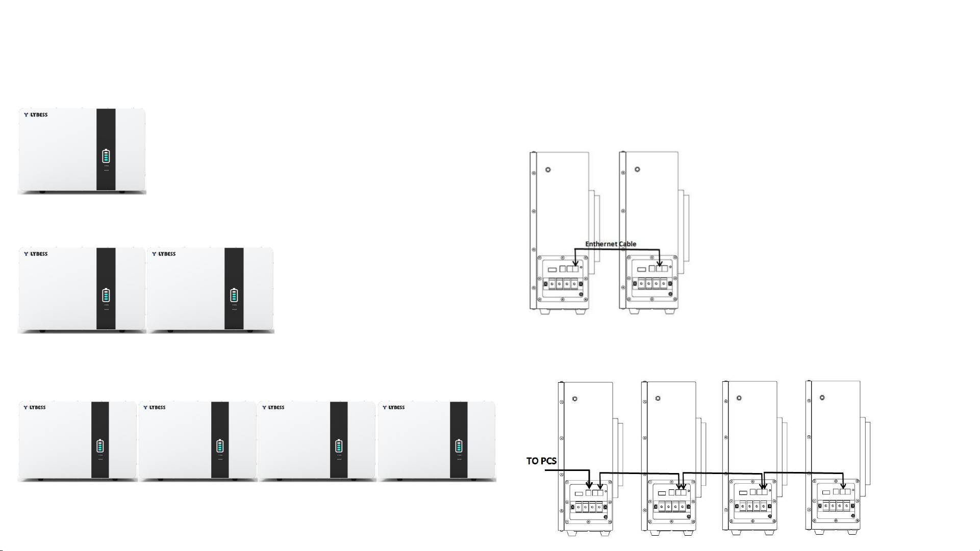
ØBatteries are not allowed in series.
ØDifferent batteries should not be connected in parallel.
ØDo not connect battery with AC directly.
ØDo not connect battery with PV wiring directly.
ØDo not connect batteries in series.
ØDo not connect battery to faulty or unqualified inverter or charger.
ØDo not create short circuits with the external connection.
ØMake sure the grid is cut off and the battery is powered off before maintenance.
ØMake sure the earth cable is connected correctly.
ØRecharge battery in every six months.
ØRecharge battery within 10 days after battery is fully discharged.
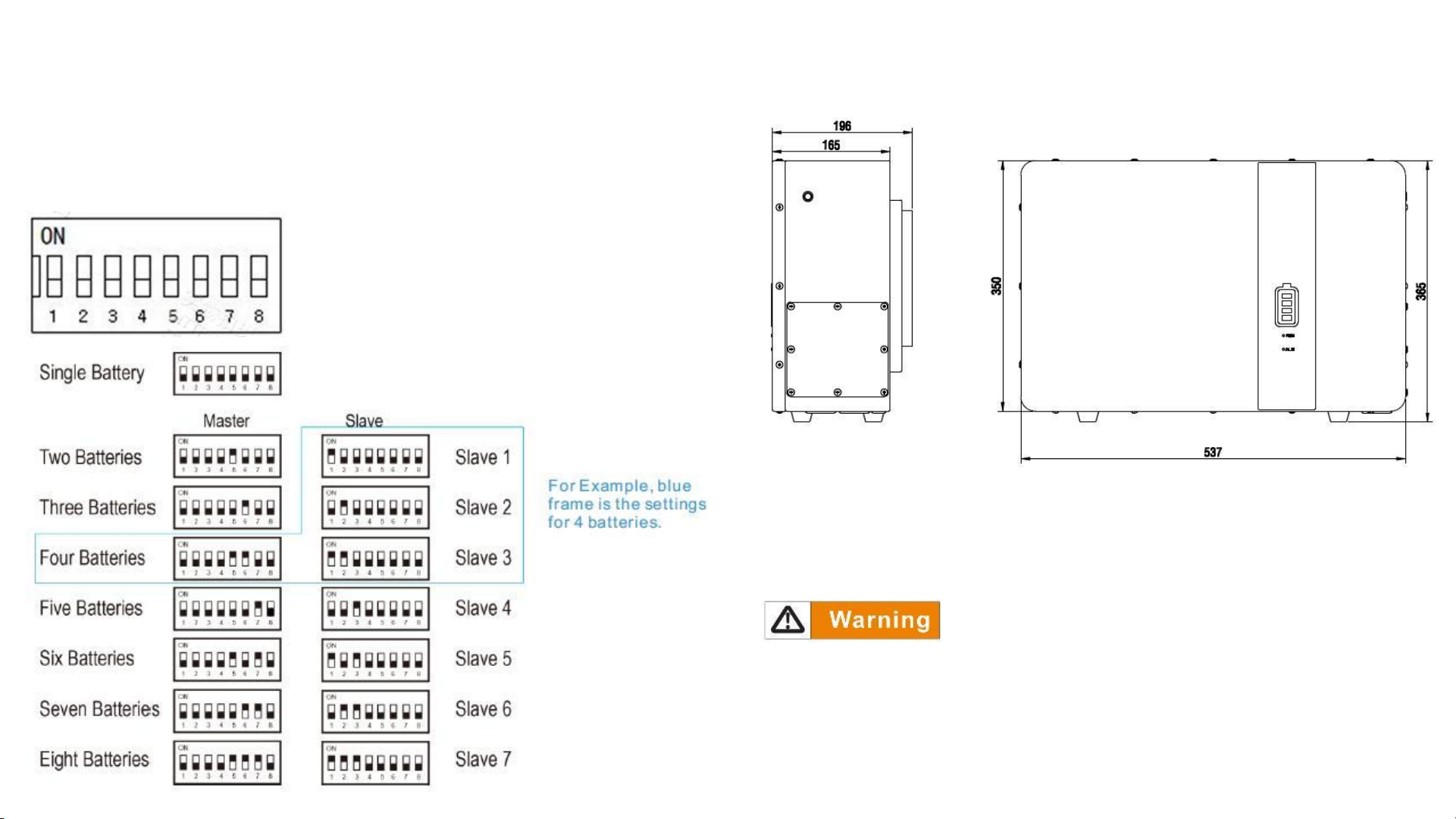
ØPlease engage greater than or equal to two batteries when maximum charge
current is more than 50A.
ØMake sure battery cable placement is installed correctly.
ØWhen the battery is being installed or repaired, make sure the battery is powered
off and using a multimeter to make sure there is no voltage in the positive and
negative terminals.
2.2 Personal Safety
Personal Requirements
People who plan to install or maintain battery equipment must be trained,
understood all necessary safety precautions, and are able to perform all operations
correctly.
Only qualified professionals or trained people are allowed to install, operate, and
maintain the equipment.
Personal Safety
ØDo not place battery at a children or pet touchable area.
ØDo not touch the energized battery, as the enclosure is hot.
ØDo not touch the energized battery terminals.
ØDo not stand on, lean on, or sit on the battery.
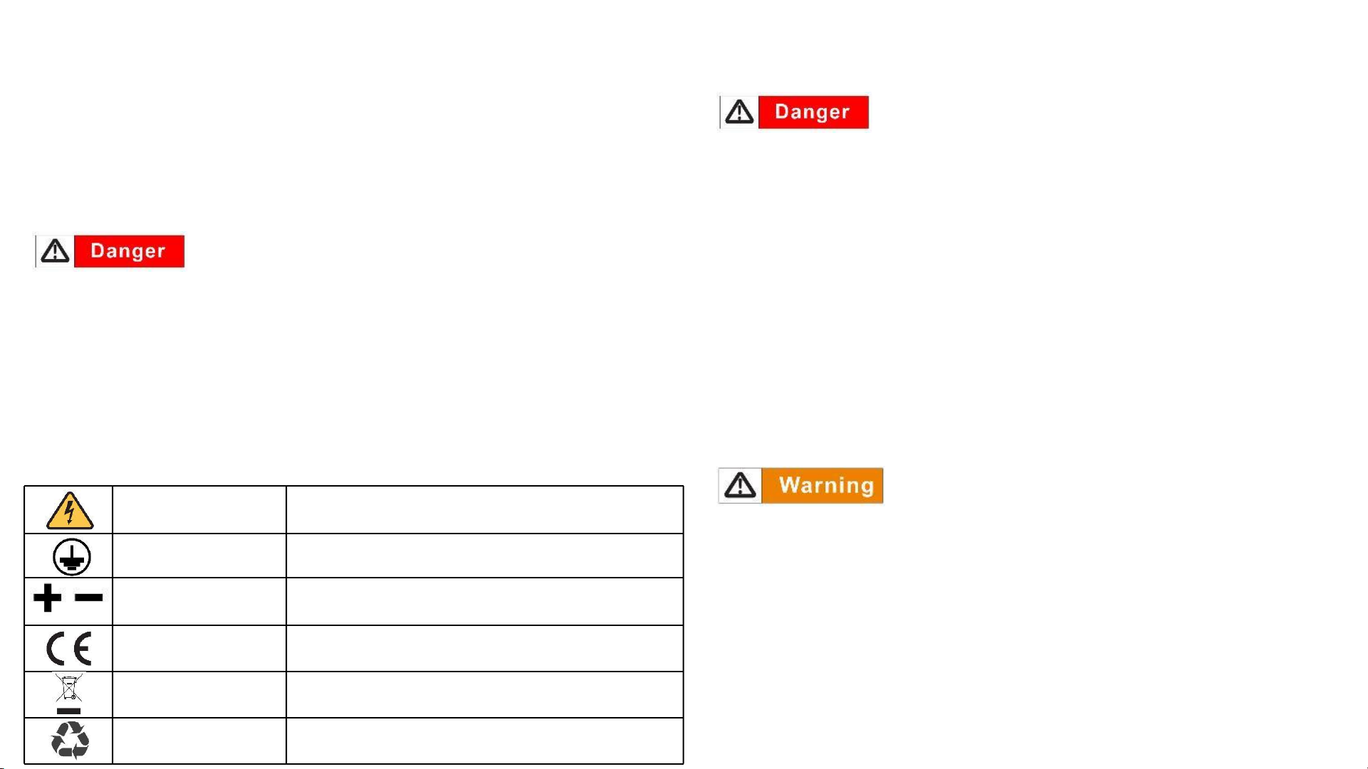
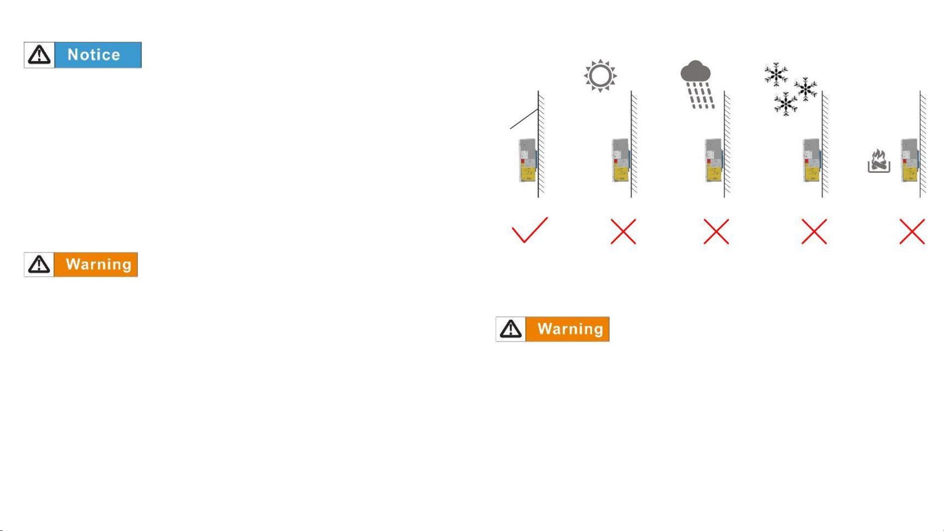
2.3 Electrical Safety
Symbols on Battery
There are some electrical symbols on battery relate to electrical safety. Please make
sure you have fully understand them before installation.
Voltage exits when the battery is powered on.
Only qualified engineers are allowed to operate.
DC positive and
negative connectors
Identify positive and negative connectors of DC
power source.
The product meets CE certification.
Can't leave battery as garbage disposal.