Lycan AKT3620 User manual

USER INSTRUCTIONS
NATURAL GAS COOKTOP
( LPG convertible )
AKT3620
AKT3020

2. Safety information..................................................................... 1-2
3. Technical Specifications............................................................ 3
4. Installing the gas cooker tops.................................................... 4-6
5. Ventilation.................................................................................. 6-7
6. Operating the Appliance............................................................. 7-8
7. Conversion Kits.......................................................................... 8-16
8. Warning...................................................................................... 16
9. Cleaning..................................................................................... 17
10. Maintenance............................................................................. 17
11. Storage..................................................................................... 17
12. Returning the appliance for Repair, Service & Warranty............ 18
13. Wiring diagrams........................................................................ 19-21
READ AND SAVE THESE INSTRUCTIONS MANUAL
CONTENTS
1. General..................................................................................... 1

CAUTION
Provide ample ventilation. This gas appliance consumes air (oxygen). Do not use
this appliance in an unventilated space to avoid endangering your life. If still more
gas appliances and/or occupants using gas are added to the space, additional
ventilation must be provided.
IMPORTANT
Read these instructions carefully before using this appliance.
Retain these instructions for future reference
― Do not store or use gasoline or other flammable vapors and
liquids in the vicinity of this or any other appliance.
― WHAT TO DO IF YOU SMELL GAS
● Do not try to light any appliance.
● Do not touch any electrical switch.
● Do not use any phone in your building.
● Immediately call your gas supplier from a neighbor’s phone.
Follow the gas supplier’s instructions.
● If you cannot reach your gas supplier, call the fire department.
― Installation and service must be performed by a qualified
installer, service agency or the gas supplier.
WARNING: If the information in these
instructions is not followed exactly, a
fire or explosion may result causing
property damage, personal injury or
death.

WARNING
WARNING
WARNING
NEVER use this appliance as a space heater to heat
or warm the room. Doing so may result in carbon
monoxide poisoning and overheating of the oven.
Electrical Grounding Instructions
This appliance is equipped with a (three-prong) (four-
prong) grounding plug for your protection against shock
hazard and should be plugged directly into a properly
grounded receptacle. Do not cut or remove the
grounding prong from this plug.
The use of cabinets for storage above the appliance
may result in a potential burn hazard. Combustible
items may ignite, metallic items may become hot and
cause burns. If a cabinet storage is to be provided the
risk can be reduced by installing a hob that projects
horizontally a minimum of 5” (12.7cm/ 5 inch) beyond
he bottom of the cabinets.
!

1
• The gas cooker top is an economic gas appliance designed for an optimal cooking
experience using natural gas. This appliance can also convert to LP gas with changing
the orifice, hose and regulator. Please refer to section 7 the conversion kit for details.
This gas appliance conforms to ANSI Z21.1-2016. CSA 1.1 - 2016 Household cooking
gas appliance
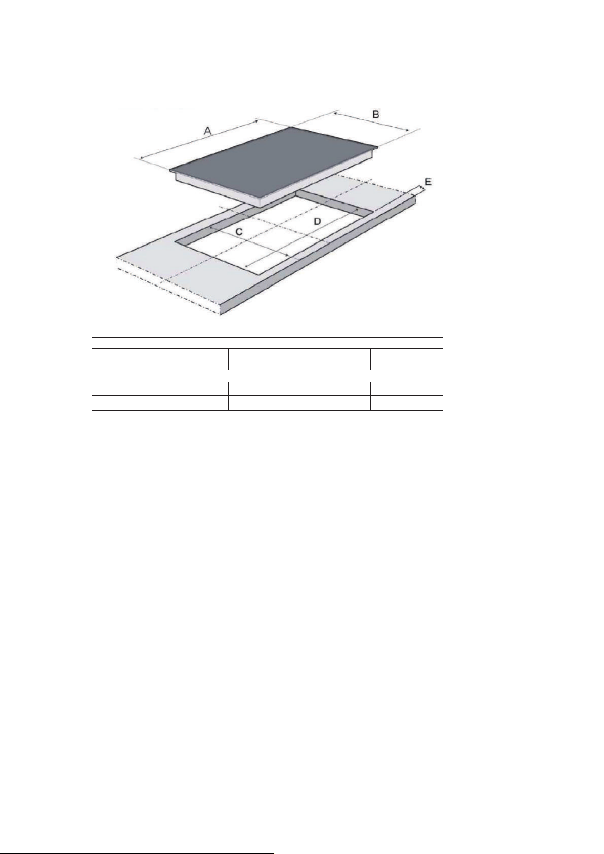
• Note that figures in this user manual are shown for visual purposes only and may differ
to your appliance.
• Please read all the instructions before use.
• It is important that all gas connections have been correctly connected to prevent any
gas leaks.
• Do not use a leaking, damaged or malfunctioning appliances.
• This appliance requires a hose and regulator to operate.
• Ensure that the appliance is used in a well-ventilated area.
• Handle the appliance with care, do not drop it.
• The installation must conform with local codes or, in the absence of local codes, with
the National Fuel Gas Code, ANSI Z223.1/NFPA 54 or, in Canada, the Natural Gas and
Propane Installation Code, CSA B149.1.
• The installation of appliances designed for manufactured (mobile) home installation
must conform with the Manufactured Home Construction and Safety Standard, Title 24
CFR, Part 3280 [formerly the Federal Standard for Mobile Home Construction and
Safety, Title 24, HUD (Part 280)] or with local codes where applicable
• The installation of appliances designed for recreational park trailers must conform with
state or other codes or, in the absence of such codes, with the Standard for
Recreational Park Trailers, ANSI A119.5
• The appliance, when installed, must be electrically grounded in accordance with local
codes or, in the absence of local codes, with the National Electrical Code, NFPA 70 or
the Canadian Electric Code, CSA C22.1-02.
• The appliance and its individual shut-off valve must be disconnected from the gas
supply piping system during any pressure testing of that system at test pressures in
excess of 1/2 psi (3.5 kPa).
• The appliance must be isolated from the gas supply piping system by closing its
individual manual shut-off valve during any pressure testing of the gas supply piping
system at test pressures equal to or less than 1/2 psi (3.5 kPa).
• The appliance is design to use 4 i.w.c outlet pressure regulator for Natural gas. It can
also convert to LP gas with using 10 i.w.c outlet pressure regulator (refer to section 7 for
details).
2. Safety information
These instructions are for your safety and to help you avoid risk of injury and/or
damage. All warranties will become void if you do not follow these instructions.
1. General

2
General safety precautions
• Please read all the instructions and warnings on the appliance before use.
• If the appliance has any visible damage or is defective, do not operate the appliance.
• Do not do any repairs or modifications on the appliance.
• Do not use the appliance if and when your judgement or coordination is impaired due to
the use of alcohol and/or drugs.
• Do not place any flammable materials close to the appliance during use or after use as
the sides may become hot.
• Make sure all ventilation slots are clear of obstructions.
• The appliance may be hot when in use. Never touch the hot burners or surfaces.
• Ensure that the control knobs are switched off after every use.
Precautions when working with gas
• Any work done on gas equipment may only be done by authorised persons who are
registered LPG gas installers.
•This appliance will be installed and connected in accordance with current installation
regulations. Attention should be given to the relevant requirements regarding ventilation.
• Only a registered gas installer may install this appliance, so make sure that the installer
signs off the installation and supply's you with an installation certificate on completion.
A gas leak is a serious fire hazard!
Put out all naked flames and do not do anything that could cause a fire.
• Gas appliances should be regularly checked for proper functioning and for any defaults.
•The regulator, hose and its clamp must be checked regularly and replaced when
necessary.
In case of a gas leak
•Turn off all control knobs on the gas appliance and close the cylinder valve.
• Open the doors and windows to ventilate the room.
• Check for leaks using soapy water and check all tubes and connections for tightness.
• If you still smell gas contact your nearest gas service centre for assistance and leave
the property.
In case of blow back on a burner:
• If you are experiencing burn back (where the flames burn back into the jet) immediately
turn off the control knob to the affected burner.
• Check that the burner is located properly and nothing is restricting the gas flow from the
jet.
• Re-light the burner.
• If burn back continues, turn off the control knob to the affected burner, and consult the
nearest service technician who will advice you on what to do next.
Note!
•This appliance is designed for domestic use only. Commercial use will void any
warrantee.
• We or any other third party shall not be held liable for any damage caused due to
improper installation, use or operation of this appliance.
•This product should not be used as a heater.

3
3. Technical Specifications
Destination
Model number
AC Electricity
Type of Gas
Gas inlet Pressure
Rating
Orifice
Max. Pan
dia.(Top)
Max. Pan
dia.(Bottom)
10,200 BTU / hr
1.53 mm / 0.06 inch
229 mm / 9 inch
216 mm / 8.5 inch
6,000 BTU / hr
1.12 mm / 0.04 inch
178 mm / 7 inch
165 mm / 6.5 inch
17,000 BTU / hr
2.10 mm / 0.083 inch
305 mm / 12 inch
298 mm / 11.7 inch
10,200 BTU / hr
1.53 mm / 0.06 inch
229 mm / 9 inch
216 mm / 8.5 inch
3,400 BTU / hr
0.86 mm / 0.034 inch
178 mm / 7 inch
165 mm / 6.5 inch
46,800 BT / hr
10,200 BTU / hr
1.53 mm / 0.06 inch
229 mm / 9 inch
216 mm / 8.5 inch
6,000 BTU / hr
1.12 mm / 0.04 inch
178 mm / 7 inch
165 mm / 6.5 inch
17,000 BTU / hr
2.10 mm / 0.083 inch
305 mm / 12 inch
298 mm / 11.7 inch
10,200 BTU / hr
1.53 mm / 0.06 inch
229 mm / 9 inch
216 mm / 8.5 inch
3,400 BTU / hr
0.86 mm / 0.034 inch
178 mm / 7 inch
165 mm / 6.5 inch
46,800 BT / hr
AKT3620
120V, 50/60Hz
NG
4 i.w.c
AKT3020
120V, 50/60Hz
NG
4 i.w.c
American (USA)
Total Rating
Rating
Orifice
Max. Pan
dia.(Top)
Max. Pan
dia.(Bottom)
Rating
Orifice
Max. Pan
dia.(Top)
Max. Pan
dia.(Bottom)
Rating
Orifice
Max. Pan
dia.(Top)
Max. Pan
dia.(Bottom)
Rating
Orifice
Max. Pan
dia.(Top)
Max. Pan
dia.(Bottom)
Left front
burner
Left rear
burner
Middle/C
enter
burner
Right
front
burner
Right
rear
burner

4
4. Installing the gas cooke tops
•We accept no liability for this service and the installation is the buyers
responsibility.
•The installation, including gas connections, must be carried out by a registered gas
installer.
•Installations by unauthorized persons will void any warranty by us and any third
party.
•We will not be held responsible for any injury or damages due to procedures
carried out by unauthorized persons and non-compliance with these provisions.
•Before installation, check if the appliance has any defects on it. If so, do not have it
installed. Damaged appliances are a safety risk.
Note to the installer
This appliance is designed for a domestic worktop. A safety distance must be left
between the appliance and the kitchen walls.
•If a vent flue is to be installed above the appliance, refer to the flue manufacturers
instructions regarding installation height (min 762 mm / 30 inch).
•Do not install with a downdraft ventilation system.
•Any surfaces, synthetic laminates and adhesives used must be heat resistant (93°C
/ 199.4℉minimum).
We and the seller are not responsible for any damage due to incorrect installation
or gas connection.
An emergency shut off valve must be installed between the regulator and the
appliance. Ensure the shut off valve used is compatible with gas.
•Flexible hose
Any connectors that is used to connect the cooker top to the gas system shall comply
with the Standard for Connectors for Movable Gas Appliance, ANSI 221.69 . CSA 6.15,
and a quick-disconnect device that complies with the Standard for Quick-Disconnect
Devices for Use With Gas Fuel, ANSI 221.41 . CSA 6.9
Information to the user on the gas hob installation
Important information for the user
Note that all installations should be done by a registered LP gas installer, failure to
do so any risks and damages are at your own discression and will void all
warranties.
On completion of the installation, the installer needs to explain the operational details of
the appliance and supply safety instructions to you. This certificate must be kept for
safety and insurance purposes.
Connecting the hose and regulator to the pipe
•Ensure that there is no gas leakage.
•Gas pipe must be located in a suitable ventilated area according to local standards.
•Always check for gas leaks after installation.
Leakage prevention

5
• It is good practice to ensure that the control knobs on the hob are off when not in use.
• Open the valve on the pipe to check for leaks, with the control knobs in the "off "
position.
• Apply some soapy water to all connections.
• Bubbles will appear if there is a leak.
• If there is a leak, close the valve immediately.
• Check and tighten all the connections.
• Repeat the procedure to ensure that there are no further leaks before using the
appliance.
Caution: NEVER use a naked flame to check for gas leaks.
Prior to first use and every time you change the gas supply
• Open gas supply.
• Check gas installations for secure fitting and tightness.
• Ignite burners and check appearance of the flame.
The flame should be blue and smooth. If the flames appear yellowish, check that the
burner cap is seated correctly or clean the burner.
Switch off the gas and let it cool before removing/replacing the burner.
Please refer to below figures for the installation details and Make sure there is a power
outlet within the reach of the cooktop's power supply cable (within 36 "/30 cm from the
left side of the cooktop). The outlet should be accessible with the cooktop installed:
Clearances
A - to back
wall
B - above
cooktop
C - side and
above
countertop
D - to any
side wall
E - to left
or right of
cooktop
adjacent
opposite
wall
F - to front of
countertop/front
vertical face
of overhead
countertop
G - max depth
of cabinets
installed above
the cooking top
3”/7.6cm 30”/76.2cm 18”/45.7cm 8”/20.3cm 36”/91.4cm 1.5”/3.8cm 13”/33.02cm

6
Cut Out Details
Dimensions
A-Width of
cooktop
B-depth of
cooktop
C-depth of
cooktop basc
D-Wodth of
cooktop basc
E-To front of
countcrtop
76 cm/30”
90 cm/36”
51 cm/20.1”
51 cm/20.1”
48 cm/18.9”
48 cm/18.9”
73 cm/28.74”
87 cm/34.25”
2” /5.1 cm
2“ /5.1 cm
• The countertop cut-out must following the dimensions given in the illustration above for
each model. Use template provided to ensure an accurate cut.
•A minimum distance between the rear wall and the back of the cooktop should be
30mm/ 1.18inch
• If cabinets are located above the cooktop, allow a minimum clearance of
762mm / 30inch between the cooking surface and the bottom of unprotected cabinets.
• Maximum depth of cabinets installed above the cooking top to be no more
330.2mm / 13inch deep
• Seal the cut surfaces with a suitable heat-resistant sealant to avoid swelling caused by
moisture
• Use the clips that are included to hold the base securely in place
• Disconnect the cooktop from electrical supply if connected before attempting to service
or move it
5. Ventilation
We recommend natural ventilation and the installation of a mechanical ventilation
device (mechanical extractor hood). Prolonged intensive use of the appliance may
require additional ventilation to be installed
Room ventilation is important for the efficient performance of the appliance and for the
safety of the occupants in the room
The room where this appliance is installed should have a window or a door that can be
opened or partially open during use.

7
If there is no window or door available for room ventilation, extra ventilation must be
installed for your safety.
Do not install this appliance in a room below ground level.
6. Operating the Appliance
Warning! Do not attempt to light the appliance if you suspect any leak or smelI gas.
•Tum on the gas by open the gas pipe valve.
• Wait for a few minutes and make sure there is no smell of gas or gas leaks.
•The hob has three settings. High, Low, and Off.
Open the pipe valve before lighting.
Read instructions before lighting
Press the control knob in and turn the control knob in an anti-clockwise from the “off ”
position until it reaches the large flame “ ” symbol the gas is ignited with the spark
created from the piezo.
If ignition does not occur in 5 seconds, tum the burner control(s) off, wait 5 minutes, and
repeat the lighting procedure.
Knob Symbols
Room size
Smaller than 5m³
5m³ and >10m³
OFF
High Flame
Low Flame
Ignition
Burner Position
OFF
Ventilation opening
min. 100cm²
min. 50cm²

8
After lighting, adjust the control knob to the desired cooking power.
Reset all control knobs to the "OFF" position after using a programmable timing
operation.
No attempt should be made to operate the appliance during power failure.
Keeping appliance area clear and free from combustible materials, gasoline, and other
flammable vapors and liquids.
Not obstructing the flow of combustion and ventilation air.
Visually checking burner flames as the right picture shows.
If necessary cleaning appliance with recommended cleaning
agents.
For your safety, top burner flame size should be adjusted so it
does not extend beyond the edge of the cooking utensil.
Leak testing of the appliance shall be conducted according to the manufacturer's
instructions.
A noncombustible material is to be installed on the underside of a cabinet located above
the broiler section or unit in accordance with local codes, or in the absence of local
codes, with the National Fuel Gas Code, ANSI Z223.1/NFPA 54 or, in Canada, the
Natural Gas and Propane Installation Codes, CSA B149.1.
Cooking
The size of the pot/pan and the flame must be compatible. Adjust the gas flames so that
they do not extend past the bottom of the pot/pan and make sure that the pot/pan is
centered on the pan support.
The large flame symbol indicates the highest cooking power and the small flame symbol
indicates the lowest cooking power.
In the turned off position (top), gas is not supplied to the burners.
7. Conversion Kits
7.1 Convert the cooker top from NG gas to LP gas:
This cooktop is set for use with Natural Gas (NG) with the pressure of 4 i.w.c. The factory
setting is indicated on the serial plate.
Warning: These orifices which are included as spare parts for use at a LP gas pressure
of 10 i.w.c supply pressure.
IMPORTANT: Both the retailer and manufacturer strongly recommend using a
qualified gastechnician to convert this grill.
An error in conversion could cause an unsafe condition leading to personal injury or
property damage. Neither the retailer nor manufacturer will be responsible for any
personal injury or property damage caused by an improperly converted appliance.
Your warranty may be voided if the conversion is improperly completed. Please retain the
parts supplied with the grill and these instructions so the technician can do the
conversion.
Different burner valves in the appliance have different ratings. The holes in the orifices
themselves are drilled to different sizes so as to allow the proper amount of gas to flow

9
through them. Please note the chart below as an easy reference for the various orifice
opening sizes for the different valves in the grill.
Destination
Model number
AC Electricity
Type of Gas
Gas inlet Pressure
Rating
Orifice
Max. Pan
dia.(Top)
Max. Pan
dia.(Bottom)
10,200 BTU / hr
0.96 mm / 0.038 inch
229 mm / 9 inch
216 mm / 8.5 inch
6,000 BTU / hr
0.74 mm / 0.029 inch
178 mm / 7 inch
165 mm / 6.5 inch
17,000 BTU / hr
1.25 mm / 0.049 inch
305 mm / 12 inch
298 mm / 11.7 inch
10,200 BTU / hr
0.96 mm / 0.038 inch
229 mm / 9 inch
216 mm / 8.5 inch
3,400 BTU / hr
0.57 mm / 0.022 inch
178 mm / 7 inch
165 mm / 6.5 inch
46,800 BT / hr
10,200 BTU / hr
0.96 mm / 0.038 inch
229 mm / 9 inch
216 mm / 8.5 inch
6,000 BTU / hr
0.74 mm / 0.029 inch
178 mm / 7 inch
165 mm / 6.5 inch
17,000 BTU / hr
1.25 mm / 0.049 inch
305 mm / 12 inch
298 mm / 11.7 inch
10,200 BTU / hr
0.96 mm / 0.038 inch
229 mm / 9 inch
216 mm / 8.5 inch
3,400 BTU / hr
0.57 mm / 0.022 inch
178 mm / 7 inch
165 mm / 6.5 inch
46,800 BT / hr
AKT3620
120V, 50/60Hz
LPG
4 i.w.c
AKT3020
120V, 50/60Hz
LPG
4 i.w.c
American (USA)
Total Rating
Rating
Orifice
Max. Pan
dia.(Top)
Max. Pan
dia.(Bottom)
Rating
Orifice
Max. Pan
dia.(Top)
Max. Pan
dia.(Bottom)
Rating
Orifice
Max. Pan
dia.(Top)
Max. Pan
dia.(Bottom)
Rating
Orifice
Max. Pan
dia.(Top)
Max. Pan
dia.(Bottom)
Left front
burner
Left rear
burner
Middle/C
enter
burner
Right
front
burner
Right
rear
burner

10
Before conversion, please ensure all necessary parts and tools are present. Ensure all
burner control knobs are in the "OFF" position, the pipe valve is closed, and the pipe is
disconnected from the regulator and removed from the cooker top. Unplug any electrical
connections.
Step 1. Convertible regulator under the cooktop, remove cap and pop out the
Pin.
Step 2. Pull out pin and flip it to the LPG position
Step 3. Take off the burner caps from the burner and then replace the orifice to LPG
orifice. Please refer to page 12 for the details orifice sizes of each burner.

11
Step 4. Save the orifices removed from the appliance for future use. And then put the
right burner caps onto the burner base.
Step 5. Connect the electric plug and the pipe, then open the valve on the pipe, ignite all
the burners and then see if the flame looks normal works on the maximum flame position
or not. If not, then turn off all the control knob. Wait until the burner cool down, and then
re-assembly the jet by seals.
Step 6. After checking the flame on the maximum opening, then turn the control knob to
the minimum flame position. Get rid of the control knob and the washer, adjust the
minimum flame to the position you want to get by turn a Ø3 screw counter clockwise.
Minimum flame height should be approx. ¼" tall.

12
Step 7. Re-assembly the washer, knob and pot stand onto the cooker top and then you
finish the conversion steps and enjoy to use this appliance with LP gas.
7.2 LPG to NG Conversion
If you want to convert the appliance back to NG, please use the NG orifices you stored
with your manual from the previous conversion.
IMPORTANT: Both the retailer and manufacturer strongly recommend using a
qualified gas technician to convert this grill.
An error in conversion could cause an unsafe condition leading to personal injury or
property damage. Neither the retailer nor manufacturer will be responsible for any
personal injury or property damage caused by an improperly converted appliance
Your warranty may be voided if the conversion is improperly completed. Please retain the
parts supplied with the grill and these instructions so the technician can do the
conversion.
Different burner valves in the appliance have different ratings. The holes in the orifices
themselves are drilled to different sizes so as to allow the proper amount of gas to flow
through them. Please note the chart below as an easy reference for the various orifice
opening sizes for the different valves in the grill.

13
Destination
Model number
AC Electricity
Type of Gas
Gas inlet Pressure
Rating
Orifice
Max. Pan
dia.(Top)
Max. Pan
dia.(Bottom)
10,200 BTU / hr
1.53 mm / 0.06 inch
229 mm / 9 inch
216 mm / 8.5 inch
6,000 BTU / hr
1.12 mm / 0.04 inch
178 mm / 7 inch
165 mm / 6.5 inch
17,000 BTU / hr
2.10 mm / 0.083 inch
305 mm / 12 inch
298 mm / 11.7 inch
10,200 BTU / hr
1.53 mm / 0.06 inch
229 mm / 9 inch
216 mm / 8.5 inch
3,400 BTU / hr
0.86 mm / 0.034 inch
178 mm / 7 inch
165 mm / 6.5 inch
46,800 BT / hr
10,200 BTU / hr
1.53 mm / 0.06 inch
229 mm / 9 inch
216 mm / 8.5 inch
6,000 BTU / hr
1.12 mm / 0.04 inch
178 mm / 7 inch
165 mm / 6.5 inch
17,000 BTU / hr
2.10 mm / 0.083 inch
305 mm / 12 inch
298 mm / 11.7 inch
10,200 BTU / hr
1.53 mm / 0.06 inch
229 mm / 9 inch
216 mm / 8.5 inch
3,400 BTU / hr
0.86 mm / 0.034 inch
178 mm / 7 inch
165 mm / 6.5 inch
46,800 BT / hr
AKT3620
120V, 50/60Hz
NG
4 i.w.c
AKT3020
120V, 50/60Hz
NG
4 i.w.c
American (USA)
Total Rating
Rating
Orifice
Max. Pan
dia.(Top)
Max. Pan
dia.(Bottom)
Rating
Orifice
Max. Pan
dia.(Top)
Max. Pan
dia.(Bottom)
Rating
Orifice
Max. Pan
dia.(Top)
Max. Pan
dia.(Bottom)
Rating
Orifice
Max. Pan
dia.(Top)
Max. Pan
dia.(Bottom)
Left front
burner
Left rear
burner
Middle/C
enter
burner
Right
front
burner
Right
rear
burner
Before conversion, please ensure all necessary parts and tools are present. Ensure all
burner control knobs are in the “OFF” position, the pipe valve is closed, and the pipe is
disconnected from the regulator and removed from the cooker top. Unplug any electrical
connections.

14
Step 1. Convertible regulator under the cooktop, remove cap and pop out the
Pin.
Step 2. Pull out pin and flip it to the NG position as below picture shows.
Step 3. Take off the burner caps from the burner and then replace the orifice to NG
orifice. Please refer to page 15 for the details orifice sizes of each burner.
Step 4. Save the orifices removed from the appliance for future use. And then put the
right burner caps onto the burner base.

15
Step 5. Connect the electric plug, pipe and then open the valve on the pipe, ignite all the
burners and then see if the flame looks normal works on the maximum flame position or
not. If not, then turn off all the control knob. Wait until the burner cool down, and then re-
assembly the jet by seals.
Step 6. After checking the flame on the maximum opening, then turn the control knob to
the minimum flame position, adjust the minimum flame to the position you want to get by
turn a Ø3 screw counter clockwise. Minimum flame height should be approx. ¼" tall.

16
Step 7. Re-assembly the washer, knobs and pot stand onto the cooker top and then you
finish the conversion steps and enjoy to use this appliance with LP gas.
8. Warning
• Do not let unauthorized persons interfere with your hob.
• Do not cover your hob while it is still hot
SURFACES MAY BE HOT!
• Use a proper pot/pan size (with flat bottom only) for each burner.
• When the content of the pan starts to boil, turn the control knob down to "low flame".
•Always put a lid on the pan.
WARNING
A child or adult can tip the range and be killed.
Install the anti-tip device to the structure and/or the range. Verify the anti-tip device has
been properly installed and engaged
Engage the range to the anti-tip device on top of the celling and the back walls.
Ensure the anti-tip device is re-engaged on top of the celling and on the back walls when
the range is moved.
Re-engage the anti-tip device on top of the celling and on the back walls if the range is
moved. Do not operate the range without the anti-tip device in place and engaged.
See installation instructions for details.
Failure to do so can result in death or serious burns to children or adults.
Warning: Disconnect the electrical supply before servicing the appliance. Please
locate the plug under the cooker top and make sure that the input electric voltage is
110 V.
This manual suits for next models
1
Table of contents
Other Lycan Cooktop manuals