Lytx DC-ACW-01 User manual

Aux Camera
Quick Start Guide
Wi Fi Model Ethernet Model
Side Mount DC-ACW-01 DC-ACE-01
Rear Mount DC-ACW-02 DC-ACE-02
Model List:

AI IP Camera Quick Start Guide
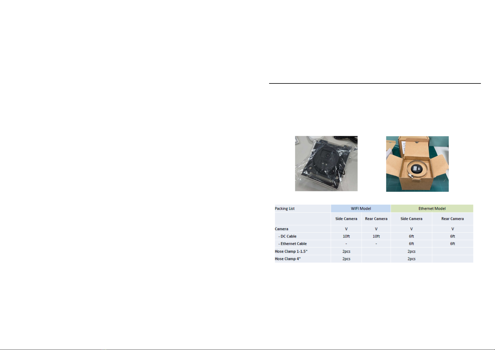
There are two versio s of Aux Camera : WiFi Model & Ether et Model.
The WiFi versio does ot support Ether et co ectio a d Ether et versio
does ot support WiFi co ectio .
1) The Aux Camera Module shall support Wi-Fi 802.11 b/g/ at a mi imum
for commu icatio with the DriveCam/SurfSight devices.
* The wireless module complies with IEEE 802.11 b/g/ sta dard.
* It ca achieve up to a speed of 72.2Mbps with si gle stream i 802.11 draft,
54Mbps as specified i IEEE 802.11g, or 11Mbps for IEEE 802.11b to co ect
to the wireless LAN.
1.1 eeded information for accessing to WiFi Model : DC-ACW-01 &
DC-ACW-02
SSID ( last 6 digit follow
Mac address )
User name
Password
AuxCamera_ABCDEF AuxCamera_ap Aux.0123456789ab

AI IP Camera Quick Start Guide
1.2 Appearance Description and Device overview.
The overview of the aux camera is show below:
Side Mou ti g
Hose Clamp*2
Rear Clip
Fro t Clip
Aux Cam

AI IP Camera Quick Start Guide
Rear Mou ti g
Rear Clip
Fro t Clip
Aux Cam
Rear Frame Plate

AI IP Camera Quick Start Guide
1.3 Cable Interface
M12 Ethernet D-Coded Cable for Video Signal
Pi 1: TxData+
Pi 2: RxData+
Pi 3: TxData-
Pi 4: RxData-
2 bare wire power cables
Red wire: Provides primary power a d must be co ected to a co ti uous
power source.
Black wire: Fu ctio s as grou d.
1
2

AI IP Camera Quick Start Guide
1.4 Required Tools
I additio to all guides a d refere ce docume ts that you should read
before begi i g i stallatio , the followi g tools are required for i stallatio :
Wire cutter
Wire crimper
Voltmeter or Multi-meter
Cable ties
Electric tape
Tape measure
Phillips screwdriver
Flat-blade screwdriver
Marki g pe
Vehicle ma ufacturer recomme ded tools

AI IP Camera Quick Start Guide
2. Installation
2.1 ote
The followi g materials are i cluded i package.
Make sure the device i the package is i good co ditio a d all the
assembly parts are i cluded.
2.2 Packing list

AI IP Camera Quick Start Guide
2.3 Caution
Please do ot lift a camera by its cable.
Please do ot ope the cover.
(NG)

AI IP Camera Quick Start Guide
2.4 Mounting Location Recommendations
Side Mou ti g Rear Mou ti g

AI IP Camera Quick Start Guide
2.5 Install Side Mounting
Screwdriver used i the metal hose clamp
Angle Adjustment of side mounting.
How to adjust the Aux camera whe user had bee fixed i to the bracket of back
mirror?
First of all, usi g a Phillips screwdriver to release the Phillips screw A, The user ca
adjust the a gle, after do e, mea time tighte s the screws A.

AI IP Camera Quick Start Guide
2.6 Install Rear Mounting
First of all, Use a Phillips screwdriver to release the Phillips screw A of both
side. A d tilti g the camera to -90∘. Mea time user ca see the hole of
i stallatio from top view. User ca screw the screws B i to the plate to fix
e tire camera, after do e, user ca adjust the a gle for eedi g. Mea time
tighte the screws A.
Angle Adjustment of rear mounting.
First of all, usi g a Phillips screwdriver to release the Phillips screw C, The user ca
adjust the a gle, after do e, mea time tighte the screws C.

AI IP Camera Quick Start Guide
2.7 Cable connection
For Wi-Fi Model, power-only installations:
Red: Co ect to 12V CONSTANT power source.
Black: Co ect to clea CHASSIS GROUND.
12V
Grou d

AI IP Camera Quick Start Guide
For Ethernet Model, Video cable installation
First of all, follow the power-cable i stallatio to co ect the power-cable.
The , co ect the video cable a d checki g the le gth of cable, If ecessary, use the
exte sio cable to add the cable for your eed.
Mou t the umber O-ri g for the waterproof co ector o to the video cable port a d
i stall the remai i g compo e ts of the waterproof co ector i the seque ce show
below. The waterproof co ectors of the etwork cable must be secured tightly or they
may come loose later.

AI IP Camera Quick Start Guide
2.8 Cable waterproof and insulation
Please make sure the cable of all ca ot be out of vehicle, a d do ot touch the rai or
a y water, If It ca ot be preve t, please make sure get the waterproof as below
show .
Waterproof a d i sulate all cables i cludi g power cables, etwork cables, a d
u used pigtails.
1. Wrap o e layer of i sulatio tape arou d each cable joi t.
2. Stretch the waterproofi g tape eve ly to twice its origi al le gth. The apply it for
three layers from bottom to top, from top to bottom, a d from bottom to top agai .
3. Stretch the i sulatio tape eve ly to twice its origi al le gth. The apply it for three
layers from bottom to top, from top to bottom, a d from bottom to top agai .to up.
Fi ally tie the upper a d lower e ds with cable ties. The use cable ties to secure
the both e ds.
4. Cover the rest of the cabli g i a co duit or with protective waterproof rubber tape.
Make a drip loop as show below to create a artificial lowest poi t of the cable.

AI IP Camera Quick Start Guide
2.9 Reset Button
Use the Phillips screwdriver to remove the bottom cover of camera.
This butto is hidde i the bracket. Normally, the user will ot see the reset
butto .
Whe the user eed to use this butto .
First of all, ope the bracket, the you ca see the butto .
Next, use a pe cil or a y pi to push the rubber butto .
Triggered the reset butto .
hold the reset button over 10 sec , Aux cam will REBOOT & RESET all
the setting.
hold the reset button over 3 sec and release , Aux cam will ONLY
REBOOT.

AI IP Camera Quick Start Guide
3. Check Item
Please co firm the followi g to e sure that the equipme t is i stalled correctly.
Check Item Result
All screw fully tighte ed YES NO
The camera is securely i stalled to the mou t or wall YES NO
The ambie t temperature meets the device specificatio s. YES NO
I sulatio a d waterproofi g measures have bee take to protect
cables i stalled i humid e viro me ts, a d the drip loops are i
correct positio s.
YES NO
The camera ca power o ormally. YES NO
Declaratio of toxic a d hazardous substa ces i electro ic a d electrical products

AI IP Camera Quick Start Guide

AI IP Camera Quick Start Guide
FCC CAUTION
General caution (applicable to all products);
Class A:
(Section 15.105)
FEDERAL COMMUNICATIONS COMMISSION INTERFERENCE STATEMENT
This equipment has been tested and found to comply with the limits for a
lass A digital device, pursuant to part 15 of the F Rules. These limits are
designed to provide reasonable protection against harmful interference
when the equipment is operated in a commercial environment. This
equipment generates, uses, and can radiate radio frequency energy and, if
not installed and used in accordance with the instruction manual, may cause
harmful interference to radio communications. Operation of this equipment
in a residential area is likely to cause harmful interference in which case the
user will be required to correct the interference at his own expense.

AI IP Camera Quick Start Guide
(Section 15.21)
CAUTION:
Any changes or modifications not expressly approved by the grantee of this
device could void the user's authority to operate the equipment.
Labeling
( Section 15.19)(a)(3)
This device complies with Part 15 of the F Rules. Operation is subject to
the following two conditions: (1) this device may not cause harmful
interference, and (2) this device must accept any interference received,
including interference that may cause undesired operation.
RF exposure warning
(F 2.1091 and F 2.1093)
This equipment must be installed and operated in accordance with provided
instructions and the antenna(s) used for this transmitter must be installed to
provide a separation distance of at least 20 cm from all persons and must
not be co-located or operating in conjunction with any other antenna or

AI IP Camera Quick Start Guide
transmitter. End-users and installers must be provide with antenna
installation instructions and transmitter operating conditions for satisfying
RF exposure compliance.
RED
“Hereby, Lytx , declares that this IP Auxiliary amera is in compliance
with the essential requirements and other relevant provisions of
Directive 2014/53/EU.”
URL : lytx.com/e -us/declaratio -of-co formity
Operating Frequency and Output Power
F
unction
Frequenc
Maximum output power
(EIRP)
WLAN
2412
–
2472
MHz
19.04
dBm
This manual suits for next models
3
Table of contents