M6DXAR
P. 1 / 4EM-7855
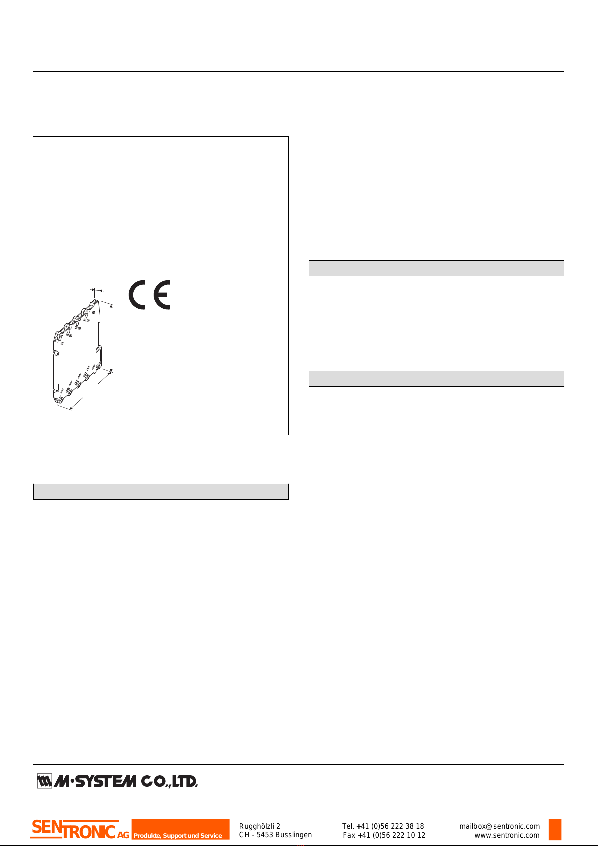
RTD ALARM
(PC programmable) MODEL M6DXAR
INSTRUCTION MANUAL
BEFORE USE ....
Thank you for choosing M-System. Before use, please check
contents of the package you received as outlined below.
If you have any problems or questions with the product,
please contact M-System’s Sales Office or representatives.
■ PACKAGE INCLUDES:
Signal conditioner......................................................... (1)
■ MODEL NO.
Confirm Model No. marking on the product to be exactly
what you ordered.
■ INSTRUCTION MANUAL
This manual describes necessary points of caution when
you use this product, including installation, connection and
basic maintenance procedures.
The M6DXAR is programmable using the PC Configurator
Software. For detailed information on the PC configuration,
refer to the M6CFG users manual. The M6CFG PC Con-
figurator Software is downloadable at M-System’s web site:
http://www.m-system.co.jp
POINTS OF CAUTION
■ CONFORMITY WITH EC DIRECTIVES
• The relay output circuit is suitable for use in Pollution De-
gree 2 environment in Overvoltage Category II with the
maximum operating voltage 250V.
Prior to installation, check that the insulation class of this
unit satisfies the system requirements.
• Altitude up to 2000 meters
•The equipment must be mounted inside a panel.
• The equipment must be installed such that appropriate
clearance and creepage distances are maintained to con-
form to CE requirements. Failure to observe these re-
quirements may invalidate the CE conformance.
■ POWER INPUT RATING & OPERATIONAL RANGE
Locate the power input rating marked on the product and
confirm its operational range as indicated below:
24V DC rating: 24V ±10%, approx. 0.5W
■ GENERAL PRECAUTIONS
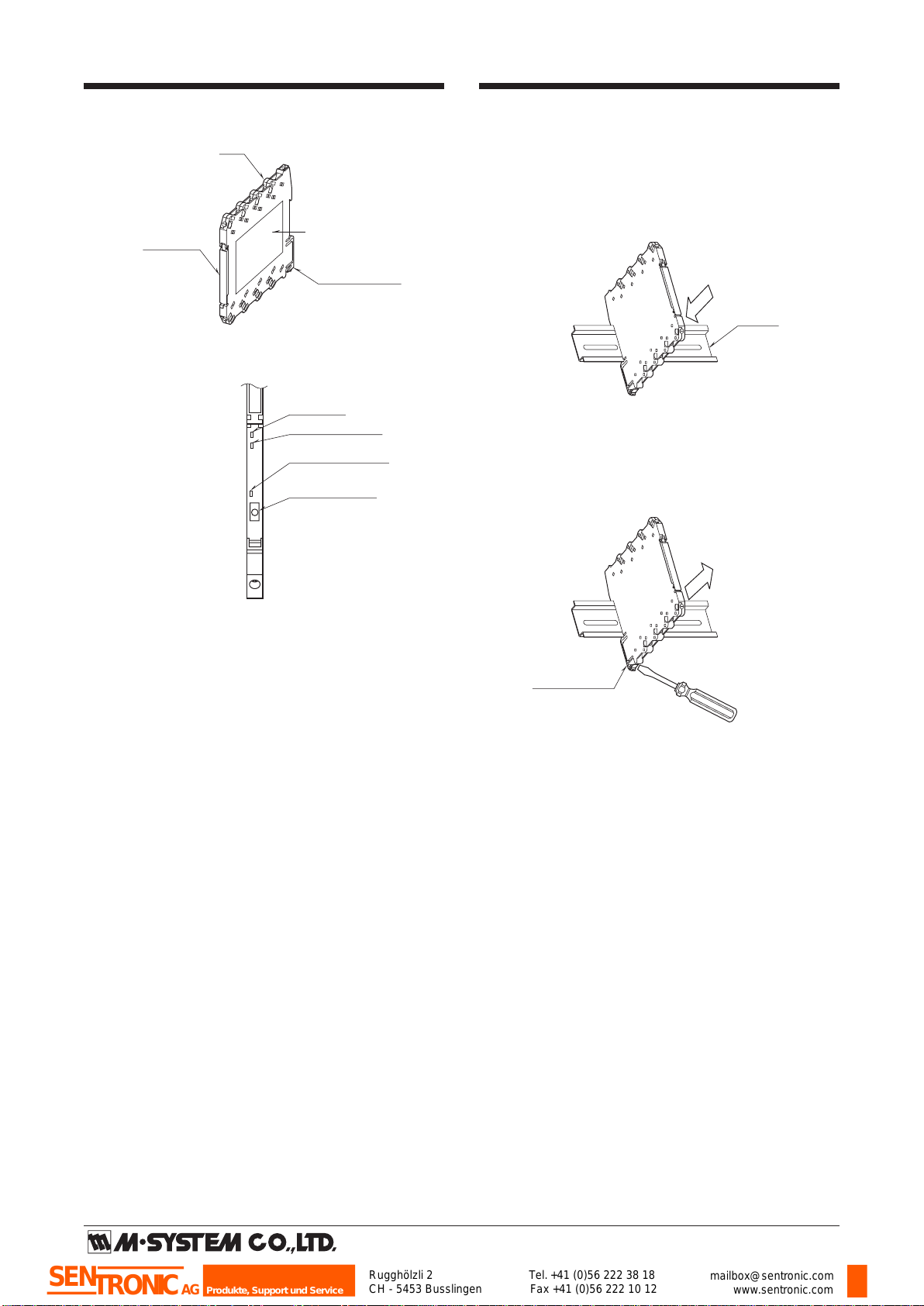
Before you remove the unit or mount it, turn off the power
supply and input signal for safety.
■ ENVIRONMENT
•Indoor use
•When heavy dust or metal particles are present in the air,
install the unit inside proper housing with sufficient ven-
tilation.
• Do not install the unit where it is subjected to continuous
vibration. Do not subject the unit to physical impact.
• Environmental temperature must be within -20 to +55°C
(-4 to +131°F) with relative humidity within 30 to 90% RH
in order to ensure adequate life span and operation.
■ WIRING
•Do not install cables (power supply, input and output)
close to noise sources (relay drive cable, high frequency
line, etc.).
• Do not bind these cables together with those in which
noises are present. Do not install them in the same duct.
■ AND ....
The unit is designed to function as soon as power is sup-
plied, however, a warm up for 10 minutes is required for sat-
isfying complete performance described in the data sheet.
Rugghölzli 2
CH - 5453 Busslingen Tel.+41 (0)56 222 38 18
Fax +41 (0)56 222 10 12 mailbox@sentronic.com
www.sentronic.com
Produkte, Support und Service
SENTRONICAG