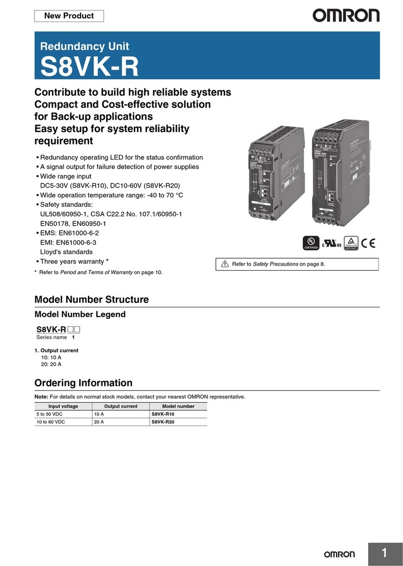
Omron XW6T Series User manual

1
Common Terminal Blocks with Visible Indicators
XW6T
Downsize Control Panels and Save Work
with Common Terminal Blocks with
Visible Indicators
• Indicators make wiring completion simply visible.
Proper wiring without skillful operators.
• Simply check the indicators for wiring maintenance,
helping reduce maintenance works.
• Short Bars enable pre-connected common wiring. No
troublesome crossover wiring required.
• The best-in-class slim models available to help downsize
control panels.
• Wiring system interface with Push-In Plus technology enables
no loosening of wiring, providing a maintenance-free operation.
Model Number Legend
Model Reference
Use this legend when determining the product specifications from the model number. Select models from Ordering Information for orders.
Part Names and Configuration
Terminal Block Basic Configuration
For the most recent information on models that have been
certified for safety standards, refer to your OMRON
website.
Refer to Safety Precautions on page 11.
XW6T - COM @@ X @@@@
(1) (2) (3)
(2) Number of Pins
8: 8 pins
12: 12 pins
16: 16 pins
20: 20 pins
40: 40 pins
(1) Maximum Applicable
Stranded Wire
1.5: 1.5 mm2
2.5: 2.5 mm2
(3) Color of Short Bars
RD: Red
BL: Blue
YL: Yellow
Terminal (insertion) hole
Release hole (to release wire)
Label attachment section
Indicator
(Wire insertion state indication part)
Insertion hole for Short Bars
• Insert the tester pins here to
perform a continuity check.
Note: Do not insert more than one wire into
each terminal (insertion) hole.
Name Description
Common
Terminal Block Five types of 8/12/16/20/40 pins are available.
End Cover
This part is required to prevent electrical shock.
Attached on the end surface (metal exposure part) of the
last terminal block.
End Brackets This part is available as an accessory. End blocks must be
attached on the both ends to hold terminal block in place.
Nameplate or
Labels
This part is available as an accessory.
Select the most suitable one for your needs.
You can also use commercially available nameplates that
are 9.5 mm wide and 0.5 mm thick.
Short Bars All pins are shorted.
Indicator Turns in green when the connection is completed.
Common Terminal Block
End Cover Order separately
Nameplate or Labels
Short Bars
Indicator
(Wire insertion state
indication part)
End Brackets

XW6T
2
Ordering Information
Model
Note: Products will be delivered in the form of common terminal blocks (with terminal blocks, a short bar, and an end cover) as shown in the
appearance.
(Example) XW6T-COM1.5X8RD set contents
Terminal block unit (4 terminals) × 2
Short bar (two-poles, red) × 1
End cover × 1
Appearance Maximum Conductor Cross
Section Fine Stranded (mm2)
Number of
pins
Color of Short
Bars Weight (g) Model
1.5
8
Red
Approx. 16
XW6T-COM1.5X8RD
Blue XW6T-COM1.5X8BL
Yellow XW6T-COM1.5X8YL
12
Red
Approx. 23
XW6T-COM1.5X12RD
Blue XW6T-COM1.5X12BL
Yellow XW6T-COM1.5X12YL
16
Red
Approx. 29
XW6T-COM1.5X16RD
Blue XW6T-COM1.5X16BL
Yellow XW6T-COM1.5X16YL
20
Red
Approx. 36
XW6T-COM1.5X20RD
Blue XW6T-COM1.5X20BL
Yellow XW6T-COM1.5X20YL
40
Red
Approx. 68
XW6T-COM1.5X40RD
Blue XW6T-COM1.5X40BL
Yellow XW6T-COM1.5X40YL
2.5
8
Red
Approx. 28
XW6T-COM2.5X8RD
Blue XW6T-COM2.5X8BL
Yellow XW6T-COM2.5X8YL
12
Red
Approx. 41
XW6T-COM2.5X12RD
Blue XW6T-COM2.5X12BL
Yellow XW6T-COM2.5X12YL
16
Red
Approx. 53
XW6T-COM2.5X16RD
Blue XW6T-COM2.5X16BL
Yellow XW6T-COM2.5X16YL
20
Red
Approx. 65
XW6T-COM2.5X20RD
Blue XW6T-COM2.5X20BL
Yellow XW6T-COM2.5X20YL
40
Red
Approx. 126
XW6T-COM2.5X40RD
Blue XW6T-COM2.5X40BL
Yellow XW6T-COM2.5X40YL

XW6T
3
Accessories (Order separately)
Terminal Block Unit (For addition)
Short Bars
*Replace the box (@) in the model number with the code for the covering color. Selection of the box (@): RD=Red, BL=Blue, YL=Yellow
End Cover
Labels
Note: 1. Different models are used for the top and side surfaces.
2. If you use commercially available nameplates (9.5 mm width and 0.5 mm thickness), you can use a commercially available printer. Check
with the manufacturer of the nameplates for information on applicable printers.
3. Refer to page 14 for details on printing labels.
End Brackets
Note: Short bars and end covers come attached to the common terminal blocks. Please select when necessary for expansion applications.
Appearance Applicable Terminal Blocks Model Application
XW6T-COM1.5X@@@@ XW6T-COM1.5 This is a Terminal Block for addition.
By using it with Short Bars as a set,
Addition of the common points is available.
Always attach the end cover after addition to prevent electrical shock.
(Refer to page 14 for details.)
XW6T-COM2.5X@@@@ XW6T-COM2.5
Appearance Applicable Terminal Blocks Number of poles Covering
color Model*Application
XW6T-COM1.5X@@@@
2
Red (RD)
Blue (BL)
Yellow (YL)
XW5S-P1.5-2@
Used for crossover wiring between
Terminal Blocks.
3XW5S-P1.5-3@
4XW5S-P1.5-4@
5XW5S-P1.5-5@
10 XW5S-P1.5-10@
XW6T-COM2.5X@@@@
2
Red (RD)
Blue (BL)
Yellow (YL)
XW5S-P2.5-2@
3XW5S-P2.5-3@
4XW5S-P2.5-4@
5XW5S-P2.5-5@
10 XW5S-P2.5-10@
Appearance Applicable Terminal Blocks Model Application
XW6T-COM1.5X@@@@ XW6E-COM1.5 This part is required to prevent electrical shock.
Attach end covers for the Terminal Blocks before use on the following
parts. (Refer to page 14 for details.)
• Exposed metal surface of the last Terminal Block
• Any Terminal Block that is next to a different shape of Terminal
Blocks.
XW6T-COM2.5X@@@@ XW6E-COM2.5
Appearance Applicable Terminal Blocks Model Minimum order in sheets
(quantity per sheet) Application
XW6T-COM1.5X@@@@
XW5Z-P1.5LB1 5 sheets with 102 top labels per sheet
Used to identify wiring.
(Material: PA resin, blank)
XW5Z-P1.5LB2 5 sheets with 108 side labels per sheet
XW6T-COM2.5X@@@@
XW5Z-P2.5LB1 5 sheets with 72 top labels per sheet
XW5Z-P2.5LB2 5 sheets with 72 side labels per sheet
Appearance Width (mm) Model Application
6XW5Z-EP6 End Brackets are installed on the both ends of the Terminal Blocks to
prevent them from moving on DIN Track.

XW6T
4
Ratings and Performance
Ratings
*1. For the applicable wire ranges, refer to page 11 for solid and stranded wires and to page 13 for ferrules.
*2. You can also use ferrules for 1.0 to 1.5 mm2wires if you use ferrules without insulation sleeve.
Performance
Model XW6T-COM1.5X@@@@ XW6T-COM2.5X@@@@
Appearance and internal
wiring
Applicable wire sizes *1
Nominal cross
section 0.75 mm2(1.5 mm2)*22.5mm
2
Minimum conductor
cross section solid 0.14 mm20.14 mm2
Maximum conductor
cross section solid 1.5 mm24.0 mm2
Minimum conductor
cross section fine
stranded
0.08 mm20.14 mm2
Maximum conductor
cross section fine
stranded
1.5 mm22.5 mm2
Minimum conductor
cross section (flex.,
stranded) with
ferrule with plastic
sleeve
0.14 mm20.14 mm2
Maximum conductor
cross Section (flex.,
stranded) with
ferrule with plastic
sleeve
0.75 mm2(1.5 mm2)*22.5mm
2
Dimensions A × 78 × 31.3 (Dimension A…8 pins: 9.2, 12 pins: 12.7,
16 pins: 16.2, 20 pins: 19.7, 40 pins: 37.2)
A × 82.6 × 36.1 (Dimension A…8 pins: 12.6, 12 pins: 17.8,
16 pins: 23.0, 20 pins: 28.2, 40 pins: 54.2)
IEC rated voltage 500 V 800 V
IEC rated current 17.5 A/1.5 mm224 A/2.5 mm2
Usage Group (UG) B, C D B, C
UL rated voltage 300 V 51 to 150 V 151 to 300 V 301 to 600 V 600 V
UL rated current
15 A/AWG14
(solid wires)
10 A/AWG16
15 A/AWG14
(solid wires)
10 A/AWG16
10 A/AWG16
5 A/AWG16-20
20 A/AWG12 (solid wire), 15 A/AWG14
Withstand voltage 1,890 VAC for 1 min (leakage current: 1 mA max.) 2,000 VAC for 1 min (leakage current: 1 mA max.)
End Cover XW6E-COM1.5 XW6E-COM2.5
Special tool XW4Z-00B XW4Z-00B
Applicable nameplates XW5Z-P1.5LB@or commercially available nameplate with 9.5 mm
width and 0.5 mm thickness
XW5Z-P2.5LB@or commercially available nameplate with 9.5 mm
width and 0.5 mm thickness
Ambient temperature
range -40 to 55°C (with no condensation or icing)
Ambient humidity range 5 to 95%RH
Insulating material PA resin
Fire resistance UL94 V-0
Insertion durability 50 times
Vibration resistance 10 to 150 Hz, Acceleration of 50 m/s2for 80 min each in X, Y, and Z directions.
Shock resistance 500 m/s2for 11 ms each in 6 directions 5 times
Ambient storage
temperature -40 to 85°C (with no condensation or icing)
Ambient storage
humidity 5 to 95%RH

XW6T
5
Standards
Compliant standard
• UL1059
• CSA (C22.2 No.158)
• IEC 60947-7-1
Certification
• cURus (File No. E245101)
Dimensions (Unit: mm)
Model
Accessories (Order separately)
(For addition) Terminal Block
25.3
78
31.3
A
XW6T-COM1.5X@@@@
Dimension A
Model Number of pins Dimensions
XW6T-COM1.5X8@@ 8 pins 9.2
XW6T-COM1.5X12@@ 12 pins 12.7
XW6T-COM1.5X16@@ 16 pins 16.2
XW6T-COM1.5X20@@ 20 pins 19.7
XW6T-COM1.5X40@@ 40 pins 37.2
A
30.1
82.6
36.1
XW6T-COM2.5X@@@@
Dimension A
Model Number of pins Dimensions
XW6T-COM2.5X8@@ 8 pins 12.6
XW6T-COM2.5X12@@ 12 pins 17.8
XW6T-COM2.5X16@@ 16 pins 23.0
XW6T-COM2.5X20@@ 20 pins 28.2
XW6T-COM2.5X40@@ 40 pins 54.2
25.3
78
31.3
3.5
XW6T-COM1.5
30.1
82.6
36.1
5.2
XW6T-COM2.5

XW6T
6
Short Bars
End Cover
End Brackets
3.5 x (poles-1) + 2.3
1. 6
3
3.5
P
18.2
XW5S-P1.5-@
Model P (mm)
XW5S-P1.5-2@3.5
XW5S-P1.5-3@7.0
XW5S-P1.5-4@10.5
XW5S-P1.5-5@14.0
XW5S-P1.5-10@31.5
XW5S-P2.5-@
Model P (mm)
XW5S-P2.5-2@5.2
XW5S-P2.5-3@10.4
XW5S-P2.5-4@15.6
XW5S-P2.5-5@20.8
XW5S-P2.5-10@46.8
5.2
23
3
1. 6
5.2 x (poles-1) + 3.7
P
25.1
78
2.2
XW6E-COM1.5
29.9
82.6 2.2
XW6E-COM2.5
55 6
40.2
33.5
XW5Z-EP6

XW6T
7
Safety Precautions
Warning Indications
• Do not drop the Terminal Block.
Terminal Block functionality may be inhibited.
• Terminal Block is designed to satisfy the functions when mounting
on the DIN Track. Always mount on the DIN Track.
• Do not exceeds the ratings. Doing so may result failure or burning.
• Mount the Terminal Block on a DIN Track and secure both ends
with the Terminal Brackets.
• Do not use Terminal Blocks in locations where toxic gases, such
as sulfide gas (H2S and SO2), ammonia gas (NH3), nitrogen gas
(HNO3), chlorine gas (Cl2), or in locations subject to high
temperature or humidity. Doing so may cause functional failure,
such as damages due to contact failure or corrosion.
• Do not use the Terminal Blocks submersed in oil or water, or in
locations continuously subject to splashes of oil or water. Doing so
may result in oil or water entering and damaging the Terminal
Blocks.
• Do not use or keep the Terminal Blocks under the following
conditions:
•Subject to severe temperature changes.
• Subject to high humidity and condensation.
• Subject to severe vibration or shock.
• Where direct rays of the sun strike.
• Where sea breeze may be present.
• When disposing, dispose the Terminal Blocks as industrial wastes.
• Do not wire anything to the release holes.
• Do not tilt or twist a flat-blade screwdriver while it is inserted into a
release hole on the terminal block. The terminal block may be
damaged.
• Insert a flat-blade screwdriver into the release holes at an angle.
The terminal block may be damaged if you insert the screwdriver
straight in.
• Do not allow the flat-blade screwdriver to fall out while it is inserted
into a release hole.
• Do not bend a wire past its natural bending radius or pull on it with
excessive force. Doing so may sever the cable. Do not apply
excessive force to the Terminal Blocks. Doing so may cause
connection failure due to damage or deformation.
• Do not insert more than one wire into each termminal insertion
hole.
•When mounting multiple Terminal Blocks, mount them so that the
conductive parts of the adjacent Terminal Blocks are facing in the
same direction. If they face in different directions, short circuit may
occur between adjacent Terminal Blocks.
• Do not use wires with discoloration, doing so may cause
conduction failure.
• When stripping the wire coatings, be sure not to damage the core
wire. Doing so may cause connection failure.
• Do not perform wiring with wet hands. Doing so may result
operation failure or malfunction when power is supplied.
• To prevent wiring materials from smoking or ignition, use the wiring
materials given in the following table with referring the ratings of
wires.
1. Precautions for Correct Use
• Always mount End Covers to the following locations when you use
Terminal Blocks.
• Exposed metal surface of the last Terminal Block
• Any Terminal Block that is next to a different shape of Terminal
Blocks.
Not doing so may result electrical shock.
• When you wire the Terminal Block, do not subject it or the wires to
stress. Secure the wires so that they do not resonate with
vibrations from the facilities in installation conditions.
• Always turn OFF the power supply before wiring. Electrical shock
may occur.
• Do not insert a flat-blade screwdriver into the indicator part.
Doing so may cause failure of function that indicates wire insertion
state.
• When you use wires thinner than AWG22 (0.34 mm2or
equivalent), the wire insertion state indication may not properly
function due to low rigidity of the conductive part.
In addition, for the indicator, moving distance of the indicator may
vary due to the feature of resin depending on the usage
environment.
Precautions
for Safe Use
Supplementary comments on what to do or
avoid doing, to use the product safely.
Precautions
for Correct
Use
Supplementary comments on what to do or
avoid doing, to prevent failure to operate,
malfunction, or undesirable effects on product
performance.
Precautions for Safe Use
Recommended wire
Stripping
length
(Ferrules not
used
)
Solid wire Stranded wire
XW6T-COM1.5X
@@@@
0.14 to 1.5 mm
2
/
AWG 26 to 14
0.08 to 1.5 mm
2
/
AWG 28 to 16
8 mm
XW6T-COM2.5X
@@@@
0.14 to 4.0 mm
2
/
AWG 26 to 12
0.14 to 2.5 mm
2
/
AWG 26 to 14
10 mm
Precautions for Correct Use

XW6T
8
2. Connecting Wires to the Push-In Plus
Terminal Block
Part Names of the Terminal Block
Connecting Wires with Ferrules (hereinafter
referred to as Ferrules) and Solid Wires
Insert the solid wire or ferrule straight into the Terminal Block
until the end strikes the Terminal Block.
If a wire is difficult to connect because it is too thin, use a flat-blade
screwdriver in the same way as when connecting stranded wire.
When the wire is inserted, the wire insertion state indication part turns
in green.
Connecting Stranded Wires
Use the following procedure to connect the wires to the terminal block.
1.
Hold a flat-blade screwdriver at an angle and insert it into the
release hole.
The angle should be between 10° and 15°. If the flat-blade
screwdriver is inserted correctly, you will feel the spring in the
release hole respond.
2.
With the flat-blade screwdriver still inserted into the release hole,
insert the wire into the terminal hole until it strikes the terminal
block. Always twist stranded wires together before inserting them.
When the wire is inserted, the wire insertion state indication part
turns in green.
3.
Remove the flat-blade screwdriver from the release hole.
Checking Connections
• When you complete wiring, an indicator for the wire insertion state
turns to green.
• To prevent short circuits, insert the stripped part of a stranded or
solid wire or the conductor part of a ferrule until it is hidden inside
the terminal insertion hole.
• After the connection, the wire insertion state indication of the
indicator may shift by a load applied to the wire at wiring or other
causes. Even in such a case, there is no problem in the electrical
connection as long as the indicator shows a part of green to
indicate the proper insertion of wire.
3. Removing Wires from the Push-In Plus
Terminal Block
Use the following procedure to remove wires from the terminal block.
The same method is used to remove stranded wires, solid wires, and
ferrules.
1.
Hold a flat-blade screwdriver at an angle and insert it into the release
hole.
2.
With the flat-blade screwdriver still inserted into the release hole,
remove the wire from the terminal insertion hole.
3.
Remove the flat-blade screwdriver from the release hole.
Release hole
Indicator
(Wire insertion state
indication part)
Terminal (insertion) hole
Ferrules or solid wire
Terminal (insertion) hole
(1)
(3)
(2)
Stranded wire
Flat-blade screwdriver
10˚ to 15˚
Wire non-insertion state:
Green is not indicated.
Wire insertion state:
Green is indicated.
(1)
(3)
(2)
wire
Flat-blade screwdriver
10˚ to 15˚

XW6T
9
4. Recommended Ferrules and Crimp
Tools
Recommended ferrules
XW6T-COM1.5X@@@@
Note: 1. Make sure that the outer diameter of the wire is smaller than
the inner diameter of the insulation sleeve of the
recommended ferrule.
2.
Make sure that the ferrule processing dimensions conform to
the following figure.
3. For the ferrule which is for applicable wire (1 to 1.5 mm2/
AWG 18 to 16), please use a ferrule without an insulation
sleeve. (Refer to the following table.)
XW6T-COM2.5X@@@@
Note: 1. Make sure that the outer diameter of the wire is smaller than
the inner diameter of the insulation sleeve of the
recommended ferrule.
2.
Make sure that the ferrule processing dimensions conform to
the following figure.
Recommended Flat-blade Screwdriver
Use a flat-blade screwdriver to connect and remove wires. Use the
following flat-blade screwdriver. The following table shows
manufacturers and models as of 2018/Dec.
*OMRON’s exclusive purchase model XW4Z-00B is available to
order as SZF 0-0,4 x 2,5 (manufactured by Phoenix Contact).
Applicable
wire
Ferrule
Conductor
length
(mm)
Stripping
length (mm)
(Ferrules
used)
Recommended ferrules
(mm
2
)
(AWG)
Manufactured
by Phoenix
Contact
Manufact
ured by
Weidmuller
Manufactured
by Wago
0.14 26 8 10 AI 0,14-8
H0.14/12
---
0.25 24
810AI0,25-8
H0.25/12
FE-0.25-8N-YE
10 12 AI 0,25-10 --- ---
0.34 22
810AI0,34-8
H0.34/12
FE-0.34-8N-TQ
10 12 AI 0,34-10 --- ---
0.50 20
8 10 AI 0,5-8 H0.5/14
FE-0.5-8N-WH
10 12 AI 0,5-10 H0.5/16
FE-0.5-10N-WH
0.75 18
810AI0,75-8
H0.75/14
FE-0.75-8N-GY
10 12 AI 0,75-10
H0.75/16
FE-0.75-10N-GY
Recommended crimp tools
CRIMPFOX6
CRIMPFOX6T-F
CRIMPFOX10S
PZ6 roto Variocrimp4
Applicable
wire
Ferrule
Conductor
length
(mm)
Stripping
length (mm)
(Ferrules
used)
Recommended ferrules
(mm
2
)
(AWG)
Manufactured
by Phoenix
Contact
Manufact
ured by
Weidmuller
Manufactured
by Wago
1/1.25 18/17
8 8 A 1-8 --- F-1.0-8
10 10 A 1-10
H1,0/10
F-1.0-10
1.25/
1.5 17/16 10 10 A 1,5-10
H1,5/10
F-1.5-10
Recommended crimp tools
CRIMPFOX6
CRIMPFOX6T-F
CRIMPFOX10S
PZ6 roto Variocrimp4
8 to 10 mm
2.1 mm max.
Processing dimensions of ferrules
2.5 mm max.
Applicable
wire
Ferrule
Conductor
length
(mm)
Stripping
length (mm)
(Ferrules
used)
Recommended ferrules
(mm
2
)
(AWG)
Manufactured
by
Phoenix
Contact
Manufact
ured by
Weidmuller
Manufactured
by Wago
0.14 26 8 10 AI 0,14-8
H0.14/12
---
0.25 24
810AI0,25-8
H0.25/12
FE-0.25-8N-YE
10 12 AI 0,25-10 --- ---
0.34 22
810AI0,34-8
H0.34/12
FE-0.34-8N-TQ
10 12 AI 0,34-10 --- ---
0.50 20
8 10 AI 0,5-8 H0.5/14
FE-0.5-8N-WH
10 12 AI 0,5-10 H0.5/16
FE-0.5-10N-WH
0.75 18
810AI0,75-8
H0.75/14
FE-0.75-8N-GY
10 12 AI 0,75-10
H0.75/16
FE-0.75-10N-GY
1/1.25 18/17
8 10 AI 1-8 H1.0/14
FE-1.0-8N-RD
10 12 AI 1-10 H1.0/16
FE-1.0-10N-RD
1.25/1.5
17/16
8 10 AI 1,5-8 H1.5/14
FE-1.5-8N-BK
10 12 AI 1,5-10 H1.5/16
FE-1.5-10N-BK
2.5 14 10 12 AI 2,5-10
H2.5/16DS
FE-2.5-10N-BU
Recommended crimp tools
CRIMPFOX6
CRIMPFOX6T-F
CRIMPFOX10S
PZ6 roto Variocrimp4
Model Manufacturer
ESD 0,40×2,5 Wera
SZS 0,4×2,5
SZF 0-0,4×2,5 *Phoenix Contact
0.4×2.5×75 302 Wiha
AEF.2,5×75 Facom
210-719 Wago
SDIS 0.4×2.5×75 Weidmuller
9900(-2.5×75) Vessel
2.6 mm max.
Processing dimensions of ferrules
2.8 mm max.
8 to 10 mm
Side
0.4 mm
2.5 mm dia.
2.5 mm
Front

XW6T
10
Equivalent Labels from Other Companies and
Recommended Label Printers
Use the following label printer.
The following table gives the manufacturer’s model number as of
August 2019.
*When using a printing tool, use a Phoenix Contact label printer.
Note: Ask the label manufacturer or printer manufacturer for details.
5. Mounting to DIN Track/Removing from
DIN Track
Mounting Method
• To mount a Terminal Block to a DIN Track, press it against the DIN
Track as shown in the following figure.
* Even when Terminal Block seems like tilting before mounting it
on the DIN Track, it is no problem for the functions.
• After mounting, push Short Bar securely and check it for no gap or
no tilting.
Removal Method
To remove a Terminal Block from the DIN Track, insert the tip of a flat-
blade screwdriver in the groove on the Short Bar, remove the Short
Bar so that lifting it up from the Terminal Block (1), operate the
screwdriver so that it catches the hook (2), and then remove the
Terminal Block with the divided state (3). However, do not apply
excessive force to the Terminal Block. Doing so may damage it.
Replacing Method
(1) Mount the Terminal Block with divided state on the DIN Track.
(2) Insert Short Bars into the insertion holes for Short Bars.
(3) Insert Short Bars for securely.
Adding Method of Common Terminal Blocks
(1) Remove the End Cover.
(2) Mount a Common Terminal Block (for addition) on the DIN Track.
(3) Replace the End Cover.
(4) Mount a Short Bar so that it overlaps with the existing Short Bar.
Manufacturer
Omron Phoenix
Contact Weidmuller Cembre
Label
XW5Z-P1.5LB1
UCT-TM3,5 NA MG-CPM-04
41392
XW5Z-P2.5LB1
UCT-TM5
MF 8/5
MG-CPM-04
41390N
MF 10/5
MF 12/5
XW5Z-P1.5LB2
UCT-TMF3,5 --- ---
XW5Z-P2.5LB2
UCT-TMF5 --- ---
Label printer --- *
BLUEMARK
CLED,
THERMOMA
RK CARD
SET PLUS,
THERMOMA
RK CARD
PrintJet
ADVCANCED,
Plotter MCP
Plus,
Plotter MCP
Basic
Markingenius
MG3
(2)
(3)
(1)
Overlapping Short Bars enables to add
the number of Common Terminal Blocks.

XW6T
11
Labels
Mounting Method
Top-surface Labels
1. Remove the Labels one at a time.
2. Insert them on the tops of the Terminal Blocks.
Note: If multiple Terminal Blocks of the same type are used side by
side, you can use multiple Labels still connected to each other.
Side-surface Labels
1. Remove the Labels one at a time.
2. Insert them on the sides of the Terminal Blocks.
Note: 1. Different models of Labels are used for the top and side
surfaces.
2. If multiple Terminal Blocks of the same type are used side
by side, you can use multiple Labels still connected to each
other.
6. Storage
Ambient storage temperature
-40 to 85°C (with no condensation or icing)
Ambient storage humidity
5 to 95%RH

OMRON CANADA, INC. • HEAD OFFICE
Toronto, ON, Canada • 416.286.6465 • 866.986.6766 • automation.omron.com
OMRON ELECTRONICS DE MEXICO • HEAD OFFICE
Ciudad de México • 52.55.5901.4300
OMRON ELECTRONICS DE MEXICO • SALES OFFICE
San Pedro Garza García, N.L. • 81.12.53.7392 • 01.800.386.6766 • mela@omron.
com
OMRON ELECTRONICS DE MEXICO • SALES OFFICE
OMRON ELETRÔNICA DO BRASIL LTDA • HEAD OFFICE
São Paulo, SP, Brasil • 55.11.2101.6300 • www.omron.com.br
OMRON ARGENTINA • SALES OFFICE
Buenos Aires, Argentina
• +54.11.4521.8630
• +54.11.4523.8483
OTHER OMRON LATIN AMERICA SALES
Authorized Distributor:
G143I-E3-01
Note: Specifications are subject to change. © 2019 Omron. All Rights Reserved. Printed in U.S.A.
Printed on recycled paper.
OMRON AUTOMATION AMERICAS HEADQUARTERS • Chicago, IL USA • 847.843.7900 • 800.556.6766 • automation.omron.com
Controllers & I/O
• Machine Automation Controllers (MAC) • Motion Controllers
• Programmable Logic Controllers (PLC) • Temperature Controllers • Remote I/O
Robotics
• Industrial Robots • Mobile Robots
Operator Interfaces
• Human Machine Interface (HMI)
Motion & Drives
• Machine Automation Controllers (MAC) • Motion Controllers • Servo Systems
• Frequency Inverters
Vision, Measurement & Identification
• Vision Sensors & Systems • Measurement Sensors • Auto Identification
Systems
Sensing
• Photoelectric Sensors • Fiber-Optic Sensors • Proximity Sensors
• Rotary Encoders • Ultrasonic Sensors
Safety
• Safety Light Curtains • Safety Laser Scanners • Programmable Safety Systems
• Safety Mats and Edges • Safety Door Switches • Emergency Stop Devices
• Safety Switches & Operator Controls • Safety Monitoring/Force-guided Relays
Control Components
• Power Supplies • Timers • Counters • Programmable Relays
• Digital Panel Meters • Monitoring Products
Switches & Relays
• Limit Switches • Pushbutton Switches • Electromechanical Relays
• Solid State Relays
Software
• Programming & Configuration • Runtime
This manual suits for next models
30
Table of contents
Other Omron Industrial Electrical manuals
Popular Industrial Electrical manuals by other brands

Murata
Murata GRM1885C2A5R9CA01 Series Reference sheet

Eaton
Eaton Memshield 3 Series Instruction leaflet

Murata
Murata GRM188R61A105MA61 Series Reference sheet

Murata
Murata GRM0335C1E5R0CA01 Series Reference sheet

Murata
Murata GRM0335C1H7R3BA01 Series Reference sheet

Murata
Murata GJM0225C1E5R5DB01 Series Reference sheet

Marconi
Marconi LORAIN RHM800E50 manual

Murata
Murata GRM0225C1H120GA03 Series Reference sheet

Murata
Murata GRM0225C1E5R4CA03 Series Reference sheet

Velleman
Velleman HIGH-Q Velleman-Kit K3400 Illustrated assembly manual

Murata
Murata GRM033C71C104ME14 Series Reference sheet

Murata
Murata GRM0335C1E390JA01 Series Reference sheet