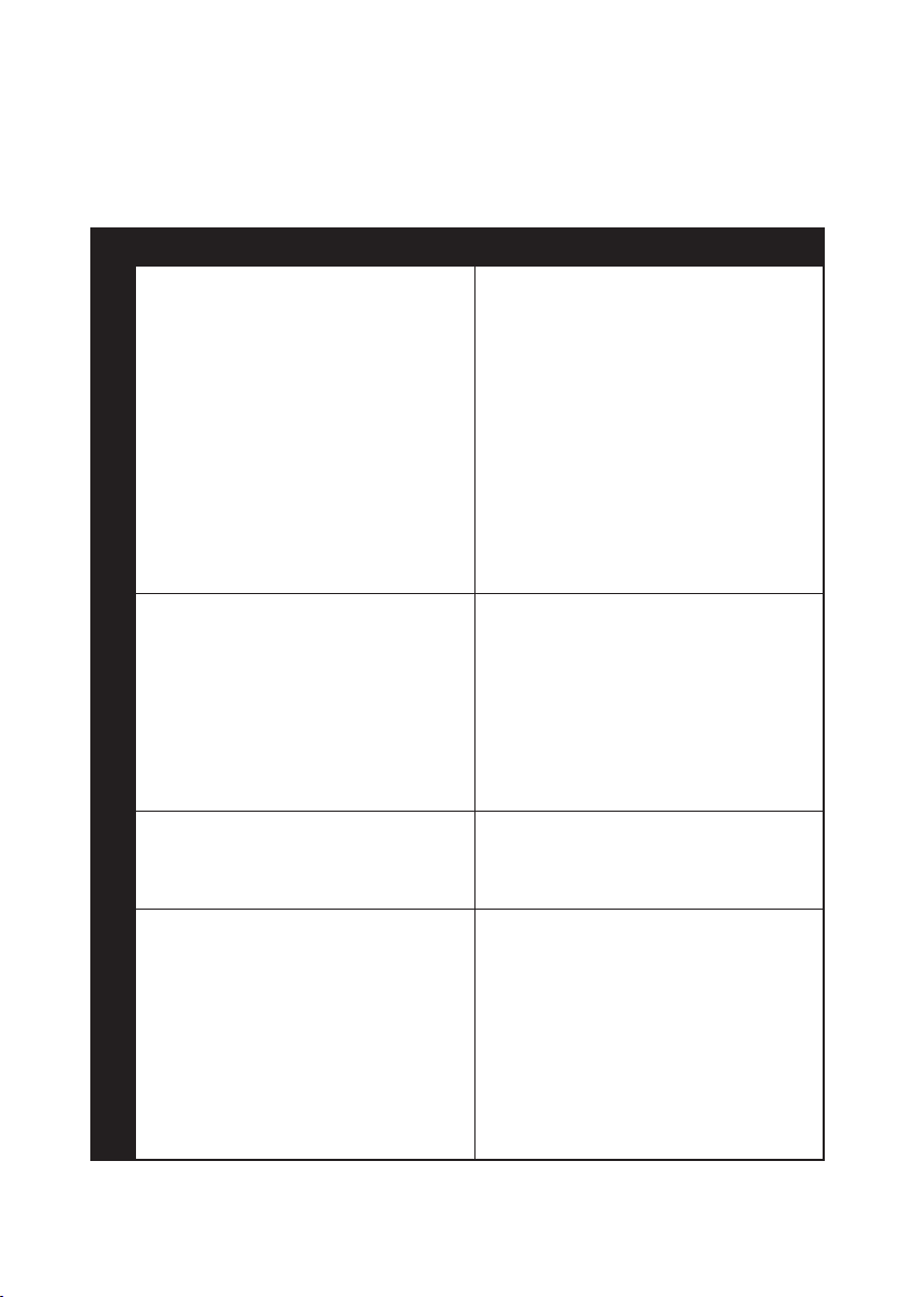
M7 SM-0502 User manual

1
WARNING:
Please read all instructions and warnings carefully
before you use
Do not use the unit with gasoline.
For security reasons, do not use the unit to extract or store dangerous chemicals, poison,
acid, alkaloid, or solvents.
Do not use the unit to extract, siphon or store petroleum or other highly inammable liquids.
Do not throw, drop or mishandle the unit.
Do not disassemble, tamper with or modify the unit for any other purpose than what it was
originally intended for.
Do not store either the unit or suction tubes near or in areas of high temperatures, direct
sunlight, rain or snow.
The unit must be instantly, drained, washed and cleaned after each use.
Air inlet : 1/4" Tank Capacity : 9.0 L
Air Consumption : 5 CFM Working Pressure : 70-170 PSI
Must perform the following procedures before use:
A. Draw out the Air Nipple (Part 63)
from the quick Coupler (Part 64)
of the Hand Pump (Part 45).
B.Use PTFE thread sealing Tape to seal thread of the Air Nipple (Part 63),
after then x it into the Air Valve (Part 62) with a Tool.
C.To set up the Tube Storage Unit ( D ) into the two hooks of Reservoir Tank ( C )

2
All Goods In The Package

3
AUTO SHOT OFF
9 LITER MANUAL & PNEUMATIC FLUID EXTRACTOR OPERATING
INSTRUCTIONS
Notes:
When using the Manual & Pneumatic Fluid Extractor
unit to extract engine oil, rst you need to make sure
the vehicle is level, and then run the engine for about
5 minutes to warm the oil and allow any sludge or
contamination within the oil to mix.
Pneumatic Operating Steps:
Instructions for extracting engine oil
1. Remove the oil dipstick from the engine
2. Insert the Extracting Tube (Part 67) into the dipstick hole until it
reaches the bottom of the oil pan. Connect the Main Suction Tube
(Part 66) into the Fluid Inlet Coupler (Part 4). The Main Suction Tube
(Part 66) will connect to the Extracting Tube (Part 67) with the Main
Suction Tube Adapter.
3.Make sure the Air Valve (Part 62) is in the “Closed” position.
4.Connect the air hose from your air compressor with a quick
coupler to the Air Nipple (Part 63), turn on the air from your air
compressor.
5.Turn Air Valve (Part 62) to the “Open” position
and press Push Button (Part 2).
The Extractor Unit will start operation
6.When the uid inside the extractor tank reaches "Full"
position, the Extractor Unit will shut off automatically.
6-1. If the uid being extracted is not sufcient to reach the
auto shut off mechanism, the unit can be shut off by turning
the Air Valve (Part 62) to the “Closed” position.
7.Disconnect the air hose now and the Main Suction Tube
(Part 66) and remove it from the dipstick hole. Open the
Fluid Inlets Coupler (Part 4) and dispose of the oil or uid in
accordance to the laws and guidelines of your state
1
2
5
6
6-17

4
Trouble shooting:
No. Trouble Cause Trouble shooting
1
When you Turn Air Valve to the
“Open” position and press Push
Button down, but the Extractor Unit
won’t start operation.
You might stand upside down the
body inclines (when it in the no uid
condition), if the body had the uid,
it might incline 45° shake several
times, and then pressed the button,
heard " click " the sound means
normal.
Please to press the blue color
button that is on the "cover
housing", if you hear the sound
in " click " obviously, means in
the normal condition. If there’s no
voice, it means abnormally.
2
When you Turn Air Valve to the
“Open” position and press Push
Button down, but the Extractor Unit
won’t start operation.
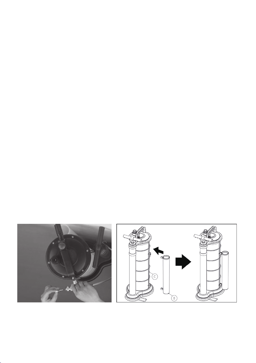
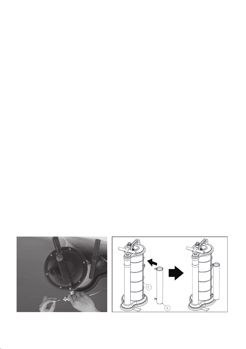
During Using, it should stain with
some lube make the internal part
more slippery. The correct place to
ll lube follow as: make the quick
coupler out rst, pump the oil in
and then jointed the quick coupler,
when the Compressor air come
in, the lube will follow air into the
internal of the Extractor unit.
3
When the uid inside the extractor
tank reaches “Full” position,
the Extractor Unit won’t shut off
Automatically.
Please to close the air valve and
stop the action, then dispose of
the uid in accordance to the laws,
use trouble shooting in step 1 and
step 2.
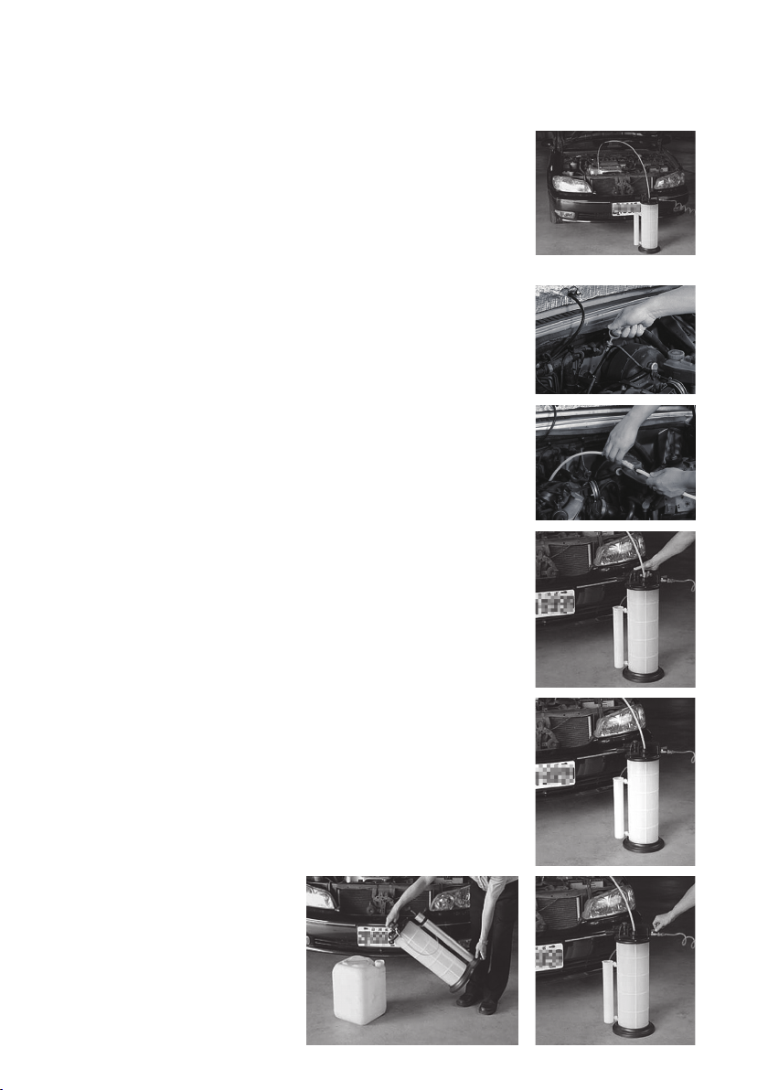
4When the Extractor Unit work on, but
it can’t suck the uid any more
To check the tube whether has
inserted the location rmly or
slip? to inspect the uid is empty
or not? to check the uid inside
the extractor tank reaches “Full”
position or not?

5
ATTENTION:
Merci de lire attentivement les instructions avant usage.
Ne pas utiliser avec de l’essence.
Par sécurité, ne pas utiliser l’appareil pour extraire des produits chimiques dangereux, des
poisons, acides, ou solvants.
Ne pas utiliser pour extraire ou siphonner du pétrole ou autres liquides extrêmement
inammables.
Ne pas lancer ou jeter l’appareil.
Ne pas démonter ou modier l’appareil dans un but autre que celui pour lequel il a été conçue.
Ne pas entreposer l’appareil ou les tubes dans des zones à températures élevées, ni au contact
direct du soleil, de la pluie ou de la neige.
L’unité doit être drainée, nettoyée et rincée immédiatement après chaque utilisation.
Les procédures suivantes doivent être réalisée
avant usage:
A.Retirer le raccord pneumatique du coupleur de la pompe à main.
B.Etanchéiez le letage du raccord pneumatique avec du ruban téon et xez le
au raccord.
C.Installez le tube de stockage (D) grâce aux deux crochets du Réservoir (C).
Pression d’usage:70-170PSI Entrée d’air:1/4"
Capacité du réservoir: 9.0 L Consommation d’air:5 CFM

6
EXTRACTEUR DE FLUIDES MANUEL & PNEUMATIQUE 9 LITRES
INSTRUCTIONS D’UTILISATION
Notes:
Avant l’utilisation de l’extracteur de uides
manuel et pneumatique, assurez vous que le
véhicule est à niveau, et faites tourner le
moteur pendant 5 minutes pour chauffer l’huile.
Instructions d’utilisation:
Instructions pour extraction d’huile moteur
1. Retirer la jauge d’huile du moteur.
2. Insérez le tube d’aspiration dans l’orice de la jauge jusqu’à
atteindre le fond du réservoir d’huile.
Connectez le tube d’aspiration principal au coupleur d’entrée de
uide. Le tube d’aspiration principal se connectera au tube d’aspiration
grâce à l’adaptateur.
3.Assurez-vous que la valve d’air est en position « fermée ».
4.Connectez le tuyau de votre compresseur avec un record
rapide à la valve et mettez en marche votre compresseu
5.Tournez la valve d’air en position “ouverte” et appuyez sur
le Bouton. L’extracteur se mettra en marche.
6.Lorsque le réservoir est plein, l’extracteur s’éteindra
automatiquement.
6-1. Si le uide extrait ne rempli pas la totalité du réservoir
et ne déclenche pas le mécanisme d’extinction automatique,
l’appareil peut être éteint manuellement en tournant la Valve
en position ″fermée″
7.Déconnectez le tuyau d’air et le tube d’aspiration principal
et retirez le, de l’orice de la jauge. Ouvrez le coupleur
d’entrée de uide et disposez de l’huile ou du uide selon la
législation de votre pays.
1
2
5
6
6-17

7
No. Cause de la panne Dépannage
1
Vous tournez la valve en position
“Ouverte” et pressez le bouton,
mais l’extracteur ne se met pas
en marche.
Pressez le bouton bleu situé sur le
couvercle de l’extracteur. Si vous
entendez distinctement un « clic »,
l’extracteur fonctionne correctement. Si
non, veuillez incliner l’extracteur (vide)
et le secouer plusieurs fois. Pressez à
nouveau le bouton, si vous entendez le
« clic », l’extracteur fonctionne.
2
Vous tournez la valve en position
“Ouverte” et pressez le bouton,
mais l’extracteur ne se met pas
en marche.
Les circuits internes de l’extracteur
doivent rester lubriés pendant
l’utilisation. An de lubrier
correctement, faire le raccord rapide
d'abord, pomper l'huile, lorsque l'air
viendra du compresseur, le lubriant
suivra l'air à l’intérieur de l’extracteur.
3
Le réservoir est plein et le niveau
de uide à atteint la position “full”
mais l’extracteur ne s’éteint pas
automatiquement.
Veuillez fermer la valve et arrêter
l’action, puis disposez du uide en
accord avec la législation. Reportez
vous aux étapes 1 et 2 du dépannage.
4L’extracteur est en marche mais
n’aspire plus de uide.
Vérier que le tube est bien inséré
dans le réservoir du véhicule. Vérier
que le réservoir de l’extracteur n’est
pas plein et a atteint la position « Full »
Dépannage:

8
ADVERTENCIA:
Lea atentamente este manual antes de usar el equipo.
Guarde el manual en un lugar seguro para futuras
consultas.
No utilice el SM-901 para extraer o almacenar combustibles (gasolina, diesel o alcohol),
solventes ácidos, líquidos tóxicos o inamables. con gasolina.
Mo use la unidad para extraer petróleo u otros líquidos altamente inamables.
Maneje el equipo con cuidado, evitando caídas o golpes que puedan dañarlo.
No intentar desarmar o modicar el equipo ni sus accesorios. No deben ser usados para
funciones diferentes a de aquellos para los que fue diseñado.
Almacene el equipo en un lugar seco y seguro, protegido de la luz directa del sol y de otras
fuetes de calor o frio intenso.
Luego de usarse, el equipo debe ser drenado de todo aceite, y limpiado completamente
antes de ser almacenado.
Antes de utilizar el equipo por primera vez, ejecute
los siguientes procedimientos:
A. Desenroscar el Conector de Aire (Parte 63) ubicado en el interior del Acople
de conexión rápida (Parte 64) de la Bomba Manual
B.Aplicar cinta plástica selladora de roscas sobre el Conector de Aire (Parte 62)
y jarlo en la Válvula de Aire (Parte 62) usando una herramienta manual.
C.Instalar el accesorio de Tubo ( D ) al lado del Tanque de Depósito ( C ), usando
los dos ganchos existentes en el lateral de este último para jarlo.
Presión de trabajo:70-170 PSI Toma de aire:1/4"
Capacidad de tanque:9.0 Litros Consumo de aire:5 CFM

9
9 MANUALES CORTOS E INSTRUCCIONES DE USO
DEL EXTRACTOR DE LÍQUIDOS NEUMÁTICO
Notas:
Antes de extraer el aceite de motor con el SM-0901,
asegúrese que el vehículo se encuentre sobre un lugar plano.
Verique también la temperatura del motor y si estuviera
frìo, dejarlo funcionando por unos 5 minutos para calentar el
aceite y levantar eventuales partículas de suciedad para que
puedan ser extraídas junto con el aceite.
Instrucciones para extraer el aceite de motor
usando aire comprimido
1. Retirar la varilla medidora de nivel de aceite del motor
2. Insertar el Tubo Extractor (Parte 67) en el agujero de la varilla
hasta que alcance el fondo del depósito de aceite de motor.
Conecte un extremo del Tubo de Succión Principal (Parte 66) al Tubo
Extractor (Parte 67) y el otro extremo al Conector de la Entrada de
Líquidos (Parte 4).
3.
Mantener la Válvula de Aire
(Parte 62)
en posición cerrada.
4.Conectar el Acople de conexión rápida de la manguera de la
compresora al Conector de Aire (Parte #63) y encender al compresora
de aire
5.Abrir la Válvula de Aire (Parte 62) y presionar el Botón de
Accionamiento (Parte 2) ubicado en la parte superior del equipo. El
aceite empezará a ser extraído del motor
6.Cuando el tanque del equipo se encuentre completamente lleno del
aceite extraído, el equipo SM-0901 se apagará automáticamente.
6-1. Si la cantidad de aceite extraído del motor no fuera suciente
para llenar el tanque del equipo y apagarlo automáticamente, se debe
cerrar la válvula de aire (Parte 62) para interrumpir el funcionamiento
del equipo una vez que todo el aceite haya sido retirado del motor.
7.Desconecte la manguera de aire de la compresora. Desconecte
también el Tubo Principal de Succión (Parte 66) y retire el tubo
extractor del canal de vericación de nivel de aceite del motor. Abra
el conector de la entrada de líquidos
(Parte 4) y descarte correctamente el
aceite extraído siguiendo las normas
locales vigentes.
1
2
5
6
6-17

10
Solución de Problemas Frecuentes:
No. Posibles Problemas Solución
1
Al abrir la Válvula de Aire y presionar el
Botón de accionamiento, la succión no
empieza a funcionar.
Debe oírse un sonido de click cada
vez que el botón de accionamiento es
presionado. Si eso no ocurriese, intentar
lo siguiente:
a) Si hubiera líquido en el tanque: incline
el equipo hasta unos 45° y balancéelo
algunas veces. Presione nuevamente el
botón y verique si se escucha el click.
b) Si el tanque estuviese vacío: voltee
el equipo poniéndolo de cabeza y
balancéelo algunas veces. Presionar el
botón y vericar si es escucha el click.
2
Al abrir la Válvula de Aire y presionar el
Botón de accionamiento, la succión no
empieza a funcionar.
Lubrique el mecanismo interno de la
siguiente forma: retire el Acople de
conexión rápida (Parte 4) e introduzca
unas gotas de lubricante. Reinstale el
acople de conexión rápida y conecte
la manguera de aire comprimido. Al
ingresar el aire de la compresora , el
lubricante será llevado hacia dentro del
equipo.
3
El tanque (Parte #18) se encuentra
completamente lleno de aceite
extraído pero la unidad no se apaga
automáticamente.
Cerrar la válvula de aire (Parte 62), vacíe
el tanque (Parte 18) y ejecute los pasos
descritos arriba en los puntos 1 y 2.
4
La unidad de Extracción continúa
funcionando pero ya no succiona más
líquidos.
When the Extractor Unit work on, but it
can’t suck the uid any more
Revisar:
a) Si el tubo de extracción de aceite
(Parte 67) alcanzó el fondo del depósito
de aceite del vehículo.
b) Si el tubo de extracción de aceite
(Parte 67) está bien conectado al tubo
principal de succión (Parte 66).
c) Si el tanque (Parte 18) no se encuentra
lleno.

11
Atenção! Leia atentamente este manual antes de
utilizar o equipamento. Guarde-o em local seguro para
futuras consultas.
Nunca utilize o SM-0901 para extrair ou armazenar combustíveis (gasolina, diesel ou
álcool), solventes, ácidos, líquidos tóxicos ou inamáveis.
Transporte o equipamento cuidadosamente, evitando quedas ou batidas que possam
danica-lo.
Não desmonte e nem modique o equipamento ou seus acessórios. Eles não devem
ser usados para outra função além daquela para a qual eles foram desenvolvidos
originalmente.
Guarde o equipamento e seus acessórios em local seco e seguro, abrigados da luz direta
do sol e de outras fontes de calor ou frio intenso.
Após o uso, drene o óleo completamente e limpe o equipamento antes de guarda-lo.
Antes de utilizar o equipamento pela primeira vez,
execute os seguintes procedimentos:
A. Desenrosque o bico de ar (nipple 63) existente no interior do conector de
engate rápido (62) da bomba manual (45).
B.Aplique um pouco de ta plástica vedadora de roscas sobre esse bico e
monte-o na válvula de ar (62) do SM-0901, usando uma ferramenta manual
C.Instale o tubo de acessórios (28) ao lado do reservatório, usando os dois
ganchos existentes na lateral desse último para xa-lo.
Pressão de trabalho:70-170 PSI Diâmetro da entrada de ar:1/4"
Capacidade do reservatório:9.0 litros Consumo de ar:5 CFM

12
Instruções para extração do óleo do motor usando
ar comprimido.
Observações importantes:
Antes de extrair o óleo do motor com o SM-0901, certique-
se que o veículo esteja em local plano. Verique ainda a
temperatura do motor. Se ele estiver frio, deixe-o funcio-
nando por 5 minutos para aquecer o óleo e levantar eventuais
partículas contaminadoras que também serão extraídas em
conjunto.
1. Remova a vareta de vericação do nível do óleo do motor.
2.
Insira o tubo extrator (67) no canal da vareta de forma que o mesmo
alcance o fundo do reservatório do óleo do motor.
Conecte uma extremidade do tubo principal de sucção (66) ao tubo
extrator (67) e a outra extremidade ao conector de entrada de líquidos (4).
3.
Mantenha a válvula de ar (62) na posição fechada.
4.Encaixe o conector de engate rápido da mangueira do compressor
de ar ao bico de ar
(nipple 63)
e ligue o compressor.
5.Abra a válvula de ar
(62)
e aperte o botão de acionamento
(2)
localizado na parte superior do equipamento SM-0901. O óleo
começará a ser extraído do motor.
6.Quando o reservatório do equipamento estiver completamente
cheio, o equipamento SM-901se desligará automaticamente.
6-1. Se a quantidade de óleo do motor não for suciente para encher
o reservatório do equipamento SM-0901 e provocar seu desliga-
mento automático, deve-se fechar a válvula de Ar
(62)
para
interromper o funcionamento do equipamento assim que todo o óleo
tenha sido retirado do motor.
7.Desconecte do equipamento a mangueira de ar do compressor.
Desconecte ainda o tubo principal de sucção
(66)
e remova o tubo
extrator
(67)
do canal de vericação do nível de óleo do motor. Abra o
conector de entrada de líquidos
(4)
e descarte corretamente o óleo
extraído, seguindo as normas
vigentes de proteção ambiental.
1
2
5
6
6-17

13
Resolução de problemas mais comuns:
No. Problema Solução sugerida
1
Ao abrir a válvula de ar (62) e apertar o
botão de acionamento (2), a sucção não
tem início.
Deve-se ouvir um leve estalo (click)
sempre que o botão de acionamento for
pressionado. Se isso no ocorre, tente o
seguinte:
a) Se houver liquido no reservatório:
incline o equipamento em 45° e
balance-o algumas vezes. Pressione
então o botão e verique, se o estalo
pode ser ouvido.
b) Se o reservatório estiver vazio: vire
o equipamento de ponta cabeça e
balance-o algumas vezes. Pressione
então o botão e verique, se o estalo
pode ser ouvido.
2
Ao abrir a válvula de ar (62) e apertar o
botão de acionamento (2), a sucção não
tem início.
Lubrique o mecanismo interno da
seguinte forma: retire o conector de
engate rápido (4), pingue algumas gotas
de óleo no e reinstale o conector de
engate rápido. Conecte a mangueira
de ar comprimido e aguarde alguns
segundos, enquanto o ar carrega a
lubricação para dentro do mecanismo.
3
Apesar do reservatório (18) se
encontrar completamente cheio, o auto-
desligamento não ocorre.
Feche a válvula de ar (62), esvazie o
reservatório (18) e efetue os passos
descritos acima nos itens 1 e 2.
4
Não ocorre a sucção de uídos apesar
de estar o equipamento acionado e
pronto para funcionamento.
Verique:
a) Se o tubo de extração de óleo (67)
atingiu o fundo do reservatório do
veículo.
b) Se o tubo de extração de óleo (67)
está bem conectado ao tubo principal de
sucção (66).
c) Se o reservatório (18) não se encontra
cheio.

14
Manual & Pneumatic Fluid Extractor
ltem No:SM-0901

15
NO. INDEX NO. DESCRIPTION QT'Y
1 SM-0901P01 Cover Housing 1
2 SM-0901P02 Push Button 1
3 SM-0901P03 Spring 1
4 SM-0901P04 Fluid Inlet Coupler 1
5 SM-0901P05 O Ring 25.2xψ2.7mm 1
6 SM-0901P06 Fluid Outlet Housing 1
7 SM-0901P07 O Ring 31xψ1.0mm 1
8 SM-0901P08 Lock Nut 1
9 SM-0901P09 Mufer Shell 1
10 SM-0901P10 O Ring 4.8xψ1.9mm 1
11 SM-0901P11 Adjustable Screw 1
11-1 SM-0901P11-1 Spring 1
12 SM-0901P12 Vacuum Valve 1
12-1 SM-0901P12-1 O Ring 4.8xψ1.5mm 1
13 SM-0901P13 O Ring 11.0xψ2.0mm 1
14 SM-0901P14 O Ring 16.3xψ2.4mm 1
15 SM-0901P15 Vacuum Body 1
16 SM-0901P16 Mufer Insert 1
17 SM-0901P17 O Ring 154.3xψ3.5mm 1
18 SM-0901P18 Reservoir Tank 1
19 SM-0901P19 O Ring 3.8xψ1.9mm 1
20 SM-0901P20 O Ring 6.0xψ2.0mm 1
21 SM-0901P21 Shaft 1
22 SM-0901P22 O Ring 3.8xψ1.9mm 1
23 SM-0901P23 Spring 1
24 SM-0901P24 O Ring 13.0xψ2.0mm 1
25 SM-0901P25 Safety Valve Housing 1
26 SM-0901T26 Screwψ3.8x10mm (6 PCS) 1 SET
27 SM-0901T27 Pin (2 PCS) 1 SET
28 SM-0901P28 Tube Storage Unit 1
29 SM-0901P29 Arm 1
30 SM-0901P30 O Ring 4.47xψ1.78mm 1
31 SM-0901P31 Safety Cup 1
32 SM-0901P32 Float 1
33 SM-0901P33 Base 1
34 SM-0901T34 Screwψ6x15mm (4 PCS) 1 SET
35 SM-0901P35 Footboard 1
36 SM-0901P36 Fixed Strip 1
NO. INDEX NO. DESCRIPTION QT'Y
37 SM-0901T37 Screw ψ4x10mm (3 PCS) 1 SET
38 SM-0901T38 Screw M8x16mm (2 PCS) 1 SET
39 SM-0901P39 Alum. Tube Base 1
40 SM-0901P40 Hex Nut M8 1
41 SM-0901P41 Piston 1
42 SM-0901P42 Piston Spacer 1
43 SM-0901T43 Flat Washer (2 PCS) 1 SET
44 SM-0901T44 Nut M5 (6 PCS) 1 SET
45 SM-0901P45 Alum. Tube 1
46 SM-0901P46 Holder 1
47 SM-0901P47 Screw M5x16mm 1
48 SM-0901P48 Nut M5 1
49 SM-0901P49 Valve Push Button 1
49-1 SM-0901P49-1 Spring 1
49-2 SM-0901P49-2 Check Valve 1
49-3 SM-0901P49-3 Shaft 1
49-4 SM-0901P49-4 O-Ring 1
49-5 SM-0901P49-5 Spring 1
49-6 SM-0901P49-6 Locking Bushing 1
50 SM-0901P50 Menu Tube 1
51 SM-0901P51 Check Valve 1
52 SM-0901P52 Quick Copper 1
53 SM-0901P53 Shaft 1
54 SM-0901P54 O Ring 48xψ2.0mm 1
55 SM-0901P55 Alum. Tube Cover 1
56 SM-0901P56 Oil Seal 1
57 SM-0901P57 Holder 1
58 SM-0901P58 Handle 1
59 SM-0901T59 Cap (2 PCS) 1 SET
60 SM-0901T60 Screw M5x20mm (6 PCS) 1 SET
61 SM-0901P61 Insert Nut 1
62 SM-0901P62 Air Valve 1
63 SM-0901P63 Nipple 1
64 SM-0901P64 Copper 1
65 SM-0901P65 Spring 1
66 SM-0901P66 Main Suction Tube
W/ Adapter 1
67 SM-0901P67 Extracting Tube
W/ Adapter 1
68 SM-0901P68 Brake Tube
W/ Rubber Fitting 1
SM-0901

16
SM-0502
2 LITER
EXTRACTEUR PNEUMATIQUE DE LIQUIDE DE
FREINS ET KIT DE RECHARGE
PNEUMATIC BRAKE
EXTRACTOR & REFILLED KIT

17
WARNING:
Please read all instructions and warnings carefully
before you use
Always read carefully and understand instructions prior to using this equipment
Brake uid is highly corrosive. Please to wear gloves and approved safety goggles at all
times, and prevent contact the uid with painted surfaces.
Do not use the unit to extract highly inammable liquids or with uids at temperatures
above 175° Fahrenheit (80° Celsius).
Consult and follow the vehicle manufacturer’s recommended procedures when servicing
any hydraulic system.
This unit is designed for vacuum use only, don’t attempt to pressurize in it.
Do not store either the unit or suction tubes near or in areas of high temperatures, direct
sunlight, rain or snow.
The unit must be instantly, drained, washed and cleaned after each use.
Working Pressure: 70-170 PSI
Air inlet: 1/4"
Tank Capacity: 2.0 L
Bottle Capacity: 1.0 L
Air Consumption: 5 CFM
All Goods In The Package

18
Extractor Unit Components
No. Description No. Description
ACover Housing G Fluid Inlet Cover
B Push Button H Extract Tube
CMufer I Air Valve
D Tank J Rubber Fitting
EAdapter Of Extract Tube KRelled Kit
FBrake Tube

19
PNEUMATIC BRAKE FLUID EXTRACTOR
AND REFILLED KIT
OPERATING INSTRUCTIONS
Principal of Operation
This unit is designed for use as a vacuum brake or clutch bleeder. It uses compressed
air between 70 psi (4.8 bar) to 170 psi (11.6 bar), for building vacuum in the tank. By
attaching the proper adapter (brake tube) to the uid outlet cover located on the top of
the unit, the vacuum can be used to drain brake uid from a hydraulic system such as
the brake or clutch systems on an automobile. It can also be used to extract a variety of
uids from reservoirs including the master cylinder or those for power steering uid.
An automatic relled kit is included with this unit. It is conveniently designed for use with
a standard bottle of brake uid, to maintain an adequate uid level in the master cylinder
while the hydraulic system is bled. Instructions are included with the unit for its use.
Instructions for Bleeding Brakes
IMPORTANT:
The procedures below are to serve as guidelines for the use of this unit, in addition to
these guidelines, always follow the manufacturer’s recommended procedures when
servicing each vehicle.
1. Properly park the vehicle on the level ground and turn the
engine off.
2. Clean the outside of the master cylinder and master cylinder
cap to prevent dirt entering the master cylinder when the cap
is removed.
3.Remove the cap from the master cylinder reservoir.
4. Connect compressed air (70 psi (4.8 bar) to 170 psi (11.6bar)
by the nipple attached to the Air Valve ( I ), located on one
end of the Cover Housing ( A ).
5. Connect the end of the proper adapter of Extract Tube ( H )
to the Fluid Inlet Cover ( G ) located on the top of the
vacuum bleeder unit.
6. Insert the other end of the Extract Tube ( H ) into the master
cylinder uid reservoir, then turn the Air Valve ( I ) on, and
press the Push Button ( B ) to start the vacuum (allow
a few seconds for vacuum to build in the bleeder reservoir
before suction occurs). While extracting the old uid,
stir it up to break loose and remove any sludge that has
accumulated on the bottom and walls of the master cylinder.
7. When all uid is removed, turn off the bleeder and rell the
master cylinder with new manufacturer’s recommended brake uid.
Removing old uid from the brake master cylinder

20
Vacuum bleed brake lines and wheel brake cylinders
Note: Prior to bleeding, ensure that the master cylinder is full of new manufacture’s
recommended brake uid. An automatic relled kit is included with the unit to maintain
the level of new uid in the master cylinder during the brake bleeding process. Follow the
instructions included with the kit to prevent air from being sucked into the master cylinder
pistons, brake lines, and wheel cylinders while the hydraulic system is bled.
1. Properly park the vehicle on the level ground and turn the
engine off, then for safe and convenient access to the
brake bleed screw that located on each wheel brake cylinder.
2. Make sure all the bleed screws are clean.
3. Connect compressed air 70 psi (4.8 bar) to 170 psi
(11.6 bar) by the nipple attached to the Air Valve ( I ),
located on one end of the Cover Housing ( A ).
4. Connect the end of the proper adapter of Brake Tube( F )
to the Fluid Inlet Cover ( G ) located on the top of the
vacuum bleeder unit.
Note:
Consult the vehicle manufacturer’s guidelines for the
vacuum bleeding procedure and the proper wheel bleeding sequence.
5. Slip the Rubber Fitting ( J ) located on the opposite end of
the brake tube ( F ), over the nipple of the bleed screw.
6. Operate the vacuum bleeder by turning the Air Valve ( I )
on, and press the Push Button ( B ) to start the vacuum
(allow a few seconds for vacuum to build in the bleeder
reservoir before suction occurs), and with the box-end
wrench, loosen/open the bleed screw slightly, until uid is
visibly draining through the bleed hose and into the Tank ( D ).
Note:
During the bleeding process, as brake uid is being
vacuumed through the bleed screw, air will also be sucked
into the bleed tube from around the bleed screw threads. This
can give the misconception that air is bleeding from the lines,
however it is normal and does not think it’s a problem. To
prevent or reduce this kind of air, coat the bleed screw threads
with silicon grease before to bleed.
7. Keep the bleed screw open until new uid is visibly owing
through the Brake Tube ( F ) (typically 20 to 30 seconds).
8. Close the bleed screw rmly, without over tightening, prior to
removing the Rubber Fitting and shutting off the Bleeder.
Table of contents
Popular Ventilation Hood manuals by other brands

ELICA
ELICA ASTI EAS428S2 Use, care and installation guide

Cavaliere
Cavaliere 218 Series installation manual

Franke
Franke FTC622XSAU user manual

Broan
Broan 893004 series installation instructions

Tricity Bendix
Tricity Bendix Visor CH 520 Operating and installation instructions

Monogram
Monogram ZV800SJSS installation instructions