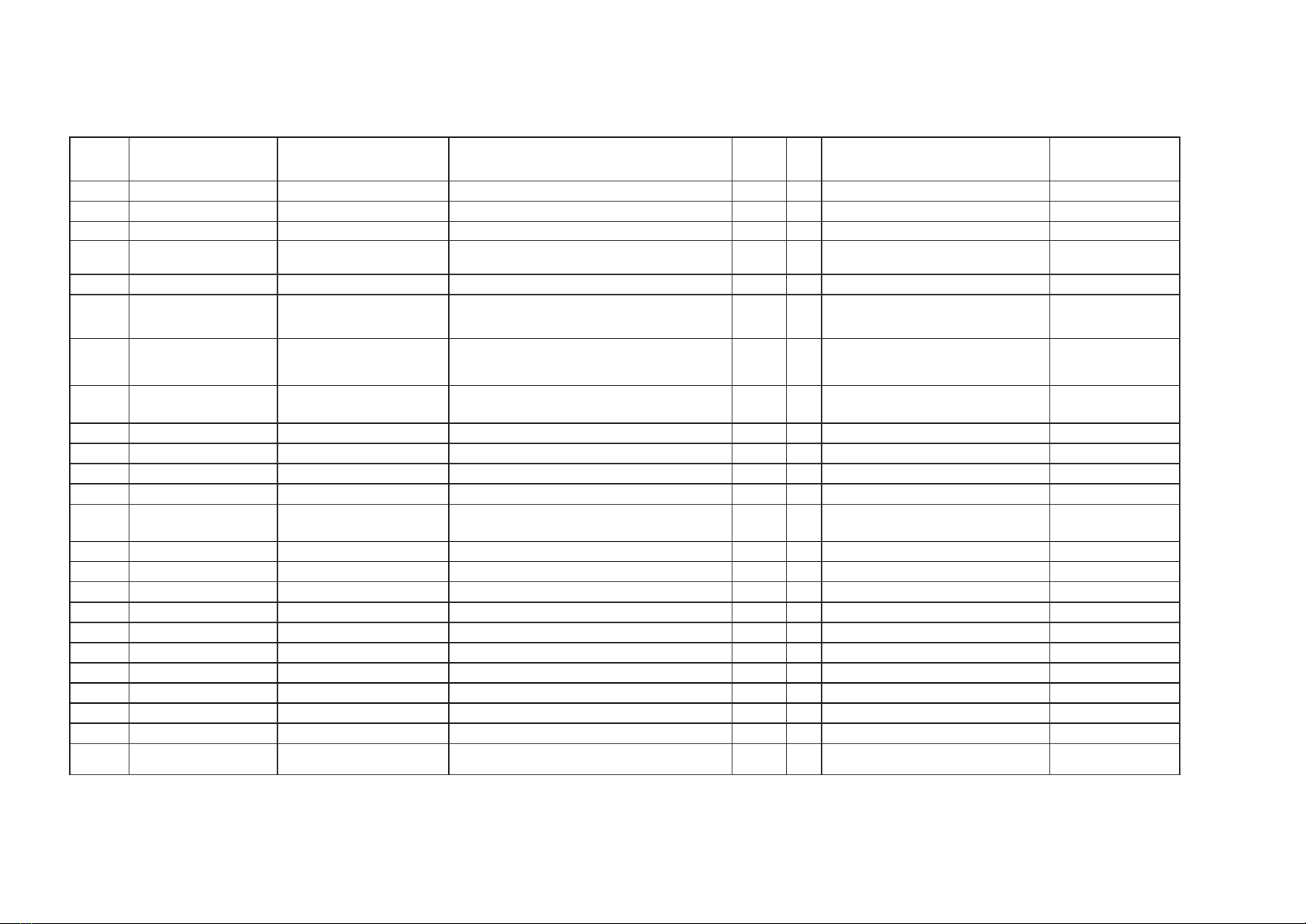
Level Material
Code Material
Name Material
Specifications Amount
of
Sub-
parts Unit Drawing Locations Change/Remarks
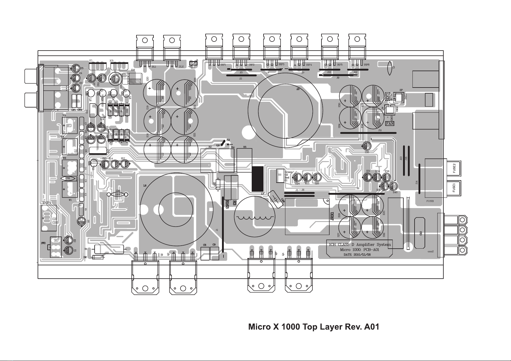
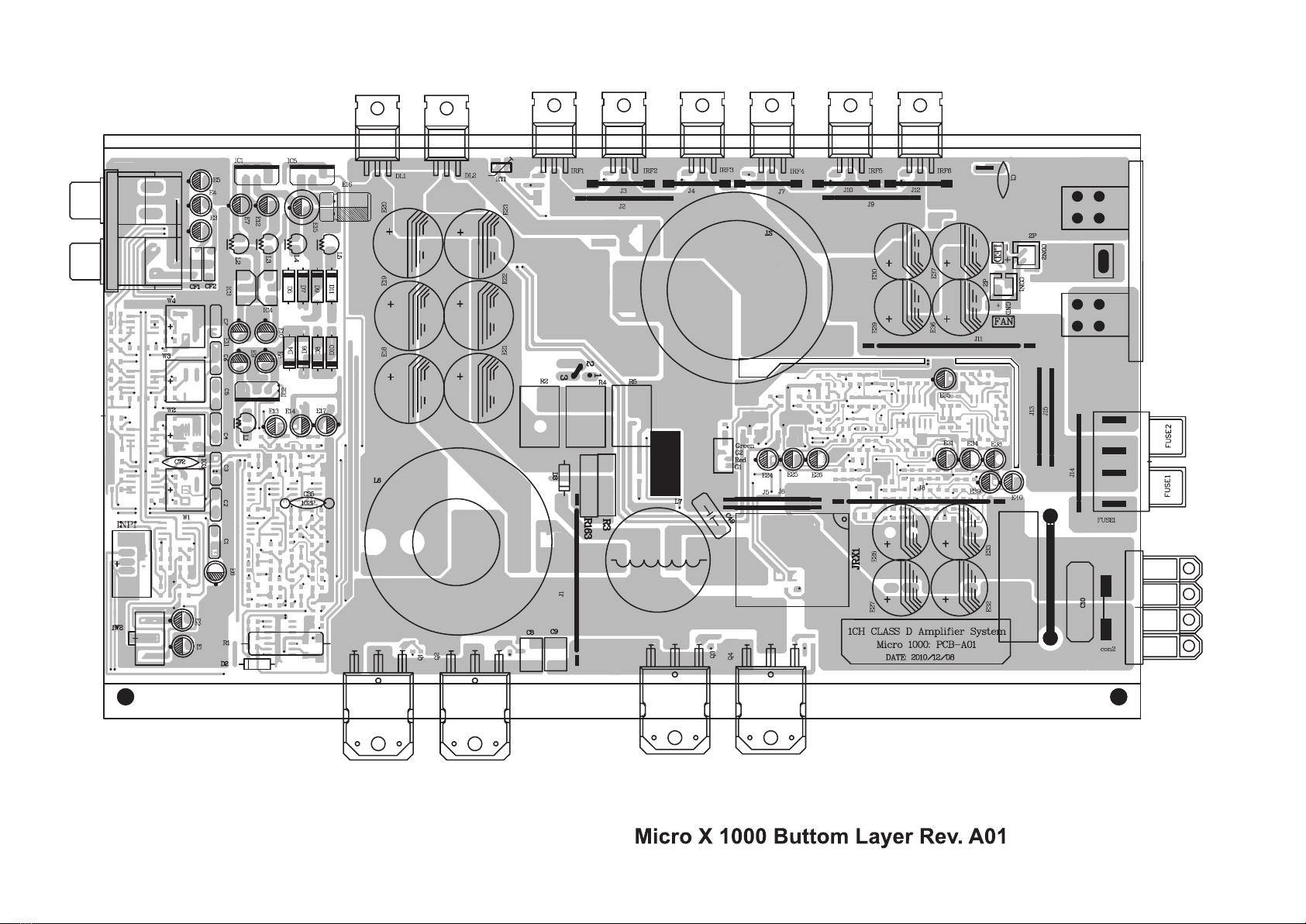
1------- 5302000130481 PCB
plug-in
board Micro
X
1000 1 PCS
-2------ 5103391130248 cable Micro
X
1000
ROHS 1 SET
--3----- 5103440010061 2P
needle
file
ROHS 2 PCS fan,lamp panel Plugin recipients
--3----- 5103440010112 4P
needle
file(1.5
separation
distance)
ROHS 1 PCS Plugin recipients
--3----- 5103530110001 Black
Single
Line 28# 0.05 M 1pcs L=50MM,include tin 2mm of each open line
--3----- 5103540010001 2P
red
and
white
winding
displacement 22#
One
end
with
block
and the
other
with
an
open
line 0.05 M L=154MM (include open line part4MM)
--3----- 5103540120011 4P
black
winding
displacement 28#
One
end
with
block
and the
other
with
pin one
distance
is
2.54MM the
other
is
1.5MM 0.12 M L=120MM spare part recipients
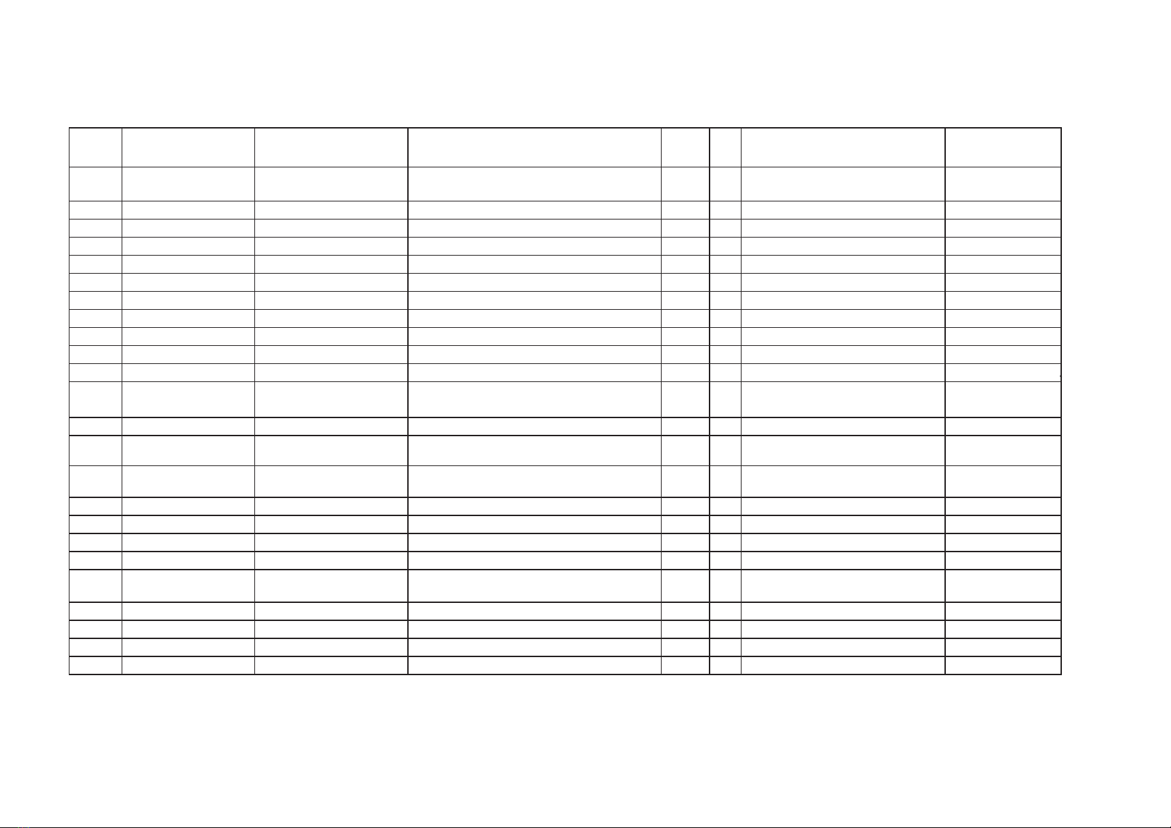
-2------ 5302000130482 PCB
plug-in
board Micro
X
1000
SMT
semi-finished
board 1 PCS
--3----- 5103040010058 Integrated
chips KA7812 1 PCS IC2
--3----- 5103040010060 Integrated
chips KA7915 1 PCS IC1
--3----- 5103040010062 Integrated
chips KA7815 1 PCS IC5
--3----- 5103070100004 Carbon
film
resistor 1w5.6ÙT=52mm
braid 2 PCS
--3----- 5103100170019 Wire-wound
resistor 3w1ÙT=52mm
braid
(globule)ö5*15mm
green
ROHS 1 PCS R1
--3----- 5103111010040 Cement resistor 5w1.2K(A)Vertical 1 PCS R5
--3----- 5103111010041 Cement resistor 5w3.3K(A)Vertical 2 PCS R2, R4
--3----- 5103131030003 Polymer
capacitor 16v47uf
black
85
braid
5*11(A) 5 PCS E6, E26, E31,E35,E40
--3----- 5103131030004 Polymer
capacitor 16v100uf
black
85
braid
6*11(A) 3 PCS E9,E10, E11
--3----- 5103131030005 Polymer
capacitor 16v220uf
black
85
braid
6*12(A) 3 PCS E7, E12, E24
--3----- 5103131120002 Polymer
capacitor 25v22uf
black
85
braid
5*11(A) 1 PCS E34
--3----- 5103131120004 Polymer
capacitor 25v100uf
black
85
braid
6.3*11(A) 1 PCS E8
--3----- 5103131220002 Polymer
capacitor 35V100uf
black
85
braid
8*12(A) 2 PCS E15, E16
--3----- 5103131320010 Polymer
capacitor 50V10uf
black
85
braid
5*11(A) 7 PCS E3, E4, E5, E14, E17, E38,E39
--3----- 5103131320012 Polymer
capacitor 50V47uf
black
85
braid
6.3*11(A) 1 PCS E13
--3----- 5103141160003 Polymer
capacitor 25v2200uf
red
105 13*25(A)XL
high
frequency
low
resistivity 4 PCS E29, E30, E36, E37
Tabulate: Examine
and
verify Approver:
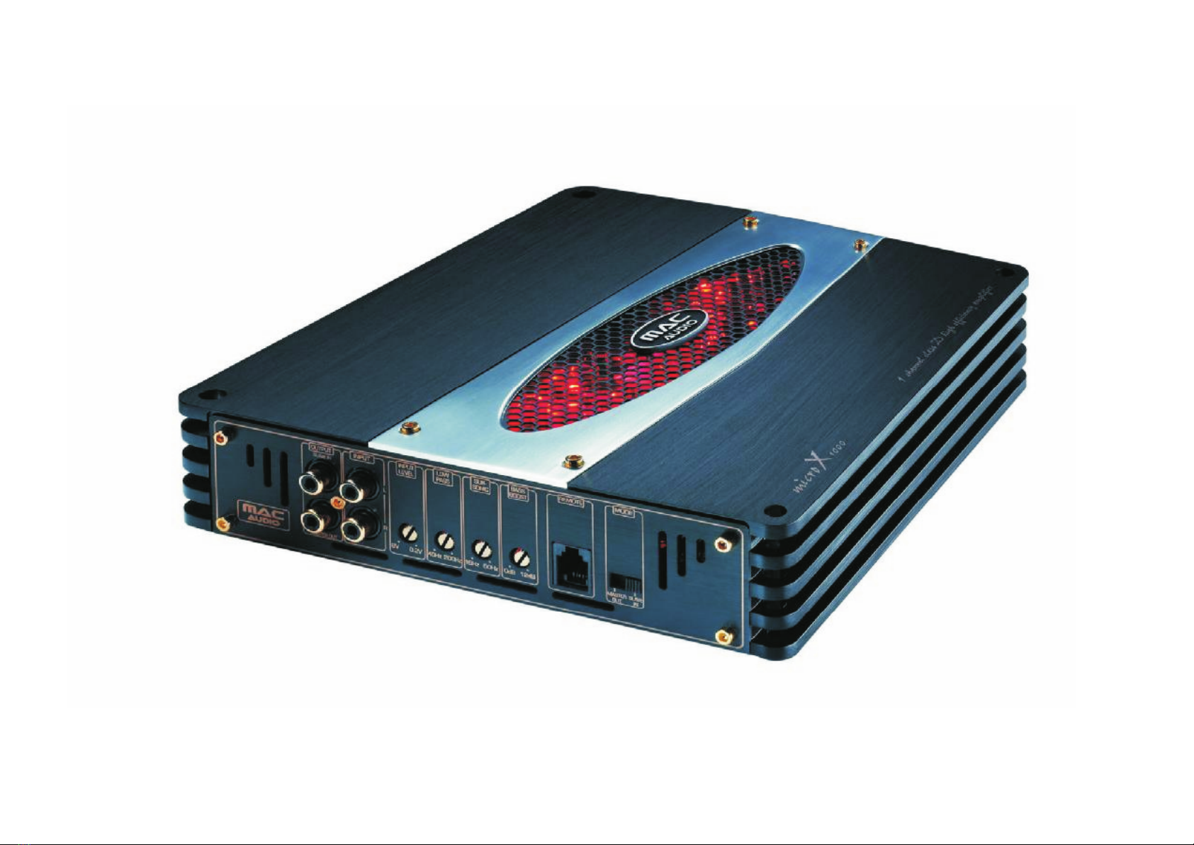
Mac
Audio
Article
Number
110
4080 Car
Amplifier
Micro
X
1000 Unit/PCS Rev.: A01
1/7 Printing Time 2011-1-6 16:07:07