Mackie TT24 User manual


Important Safet
y
Instruction
s
1
.
R
ead
th
ese
in
s
tr
uc
ti
o
n
s
.
2
.
Kee
p
these instructions
.
3
. Heed all warnin
g
s
.
4. Follow all instructions.
5. Do not use this apparatus near water.
6. Clean only with dry cloth.
7. Do not block any ventilation openings. Install in
accordance with the manufacturer’s instructions.
8. Do not install near any heat sources such as
radiators, heat registers, stoves, or other
apparatus (including amplifiers) that produce heat.
9. Do not defeat the safety purpose of the polarized
or grounding-type plug. A polarized plug has two
blades with one wider than the other. A grounding-
type plug has two blades and a third grounding
prong. The wide blade or the third prong are
provided for your safety. If the provided plug does
not fit into your outlet, consult an electrician for
replacement of the obsolete outlet.
10. Protect the power cord from being walked on or
pinched particularly at plugs, convenience
receptacles, and the point where they exit from
the apparatus.
11. Only use attachments/accessories specified by
the manufacturer.
12. Use only with a cart, stand, tripod, bracket, or
table specified by the manufacturer, or sold with
the apparatus. When a cart is used, use caution
when moving the cart/apparatus combination to
avoid injury from tip-over.
13. Unplug this apparatus during lightning storms or
when unused for long periods of time.
14. Refer all servicing to qualified service personnel.
Servicing is required when the apparatus has
been damaged in any way, such as power-supply
cord or plug is damaged, liquid has been spilled
or objects have fallen into the apparatus, the
apparatus has been exposed to rain or moisture,
does not operate normally, or has been dropped.
15. This mixer has been designed with Class-I
construction and must be connected to a mains
socket outlet with a protective earthing connection
(the third grounding prong).
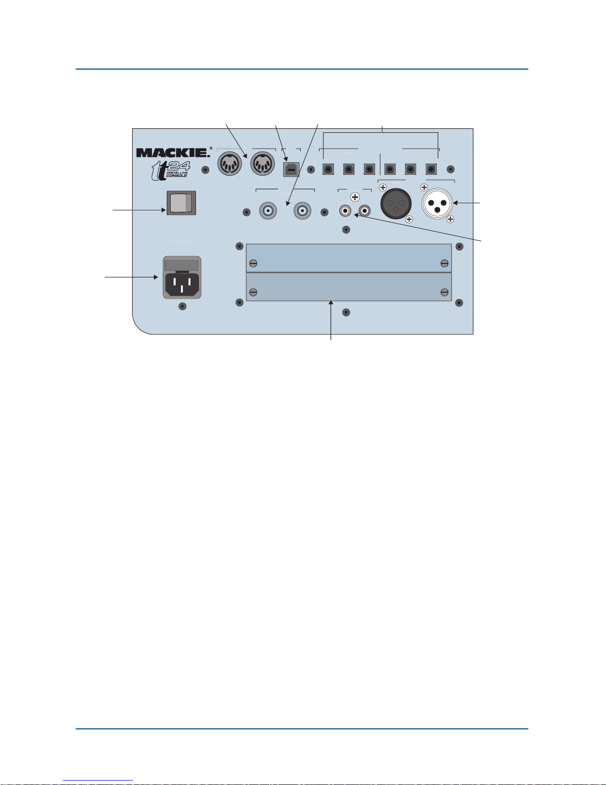
16. This mixer has been equipped with an all-pole,
rocker-style AC mains power switch. This switch is
located on the rear panel and should remain
readily accessible to the user.
17. This apparatus does not exceed the Class A/Class
B (whichever is applicable) limits for radio noise
emissions from digital apparatus as set out in the
radio interference regulations of the Canadian
Department of Communications.
ATTENTION — Le présent appareil numérique
n’émet pas de bruits radioélectriques dépassant las
limites applicables aux appareils numériques de
class A/de class B (selon le cas) prescrites dans le
réglement sur le brouillage radioélectrique édicté
par les ministere des communications du Canada.
18. Exposure to extremely high noise levels may
cause permanent hearing loss. Individuals vary
considerably in susceptibility to noise-induced
hearing loss, but nearly everyone will lose some
hearing if exposed to sufficiently intense noise for
a period of time. The U.S. Government’s
Occupational Safety and Health Administration
(OSHA) has specified the permissible noise level
exposures shown in the following chart.
According to OSHA, any exposure in excess of
these permissible limits could result in some
hearing loss. To ensure against potentially
dangerous exposure to high sound pressure
levels, it is recommended that all persons
exposed to equipment capable of producing high
sound pressure levels use hearing protectors
while the equipment is in operation. Ear plugs or
protectors in the ear canals or over the ears must
b
e worn w
h
en operat
i
n
g
t
h
e equ
i
pment
i
n or
d
er to
prevent permanent hearin
g
loss if exposure is in
e
x
cess
o
f th
e
limit
s
se
t f
o
rth h
e
r
e
.

Mackie TT24 Digital Live Console Quickstart Guide
iii
Table of Contents
Chapter 1: Introduction..................................................................................... 5
1.1 Evolution of the TT24 Console ...................................................... 5
1.2 Summary of Features .................................................................... 5
1.2.1 Rear Panel Connections...................................................... 6
1.2.2 DSP Functionality............................................................... 8
1.3 Terminology and Conventions..................................................... 10
Chapter 2: TT24 Interface............................................................................... 11
2.1 Channel Strip............................................................................... 11
2.2 Banks............................................................................................ 12
2.3 V
-
Pot Control Area ...................................................................... 14
2.4 QuickMix Area ............................................................................. 14
2.5 Snapshots ..................................................................................... 16
2.6 Flex Groups and Master .............................................................. 16
2.7 Matrix
-
Plus .................................................................................. 17
2.8 Utility Area .................................................................................. 18
2.9 TT Control Software .................................................................... 18
Chapter 3: Quickstart Tutorial ..................................................................... 19
3.1 Connect Amplifier/Speakers........................................................ 19
3.2 Connect a Mic............................................................................... 20
3.3 Connect a CD/Tape Device .......................................................... 23
3.4 Aux Functions .............................................................................. 25
3.5 Effects ........................................................................................... 27
Chapter 4: TT24 Specifications.................................................................... 28
Appendix A: TT24 Configurations and Block Diagrams.................. 32

Mackie TT24 Digital Live Console Quickstart Guide
iv
Print Version: Part No. 0012118 Rev. C 7/04
Web Version: Part No. SW0134 Rev. C 7/04
©2004 LOUD Technologies Inc.
All Rights Reserved.

Mackie TT24 Digital Live Console Quickstart Guide
5
Chapter 1: Introduction
1.1 Evolution of the TT24 Console
The professional live sound industry has been revolutionized over the past few
years by high
-
end digital consoles. However, mid
-
size digital consoles have
tended to emphasize studio applications with user interfaces encumbered by
features (i.e., DAW control) not critical for live applications. Some of these
consoles conceal their real cost by
requiring
the purchase of additional cards to
supplement their limited physical I/O.
The
TT24 Digital Live Console
is a mid
-
size digital mixer optimized for live
sound applications. We have used our extensive expertise and experience de-
signing analog mixers to produce a powerful, easy
-
to
-
use digital console for a
wide range of applications and budgets:
• theaters and houses of worship;
• permanent concert installations;
• professional live music touring companies.
1.2 Summary of Features
•24
-
bit/96 kHz mixing console designed for live applications
• 24 mic/line inputs with 4
-
band EQ/comp/gate/HPF/polarity invert (can be
stereo linked)
• Eight line inputs with 4
-
band EQ (can be stereo linked)
• Instant recall of 99 snapshots with filtering
• Rear panel connections:36x28 analog I/O;28x28 digital I/O
• QuickMix section with 5.5
-
inch touch LCD, 12 push
-
button rotary encoders,
and QuickMix buttons
• 29 100
-
mm motorized faders
• 28 multi
-
function V
-
Pots
• 12 Aux sends with 4
-
band parametric EQ + dual kill filters and compressor/
limiter

Mackie TT24 Digital Live Console Quickstart Guide Introduction
6
• Left
-
Right and CTR/Mono outputs with 4
-
band EQ + dual kill filters and
compressor/limiter
• Aux Mode enables instant monitor mixing
• 11x8 Matrix
-
Plus with patchable inputs
•Eightuser
-
definable flex
-
groups
• 2 expansion card slots
•Dual
-
console linking for a maximum 96 input console
• TT control software to control and view console parameters via PC
1.2.1 Rear Panel Connections
Analog I/O
Figure 1-1 shows the rear panel analog I/O connectors except for the Group/
Matrix outputs, which are shown in Figure 1-2.
Figure 1-1 Analog I/O
Figure 1-2 Group/Matrix connectors
CD
/
TAPE
A
TALK B A
CK
OUT
IN
LINE
IN
S
ER
T
LINE
IN
S
ER
T
LINE
IN
S
ER
T
LINE
IN
S
ER
T
LINE
IN
S
ER
T
LINE
IN
S
ER
T
LINE
IN
S
ER
T
LINE
I
N
S
ER
T
LINE
IN
S
ER
T
LINE
IN
S
ER
T
LINE
IN
S
ER
T
LINE
IN
S
ER
T
LINE
IN
S
ER
T
LINE
IN
S
ER
T
LINE
IN
S
ER
T
1
2
3
4
5
6
7
8
9
1
0
11
12
1
3
14
15
CTR/MONO
RI
G
H
T
LEFT
M
O
NIT
O
R
MAIN
S
OUT
LINE INP
U
T
S
A
U
X
S
END
S
1
2
3
4
5
6
7
8
9
1
0
11
12
L
R
C
24 Mic, Line
and Insert
Analog
Inputs
12 Aux
Sends
8 Analog Line Inputs
Monitor
Outputs
CD/Tape B
Inputs
CD/Tape A
Inputs/Outputs
Talkback
Input
Main Outputs
R
M
L
1
2
3
4
5
6
7
8
R
L
1
2
3
4
5
6
7
8
GROUP
/
MATRIX OU
T
Group/Matrix Outputs

Mackie TT24 Digital Live Console Quickstart Guide Introduction
7
Inputs
• 24 mic/line inputs with inserts (mic = balanced XLR;line = balanced TRS;
inserts = unbalanced Tip Send
-
Ring Return)
• Eight analog line inputs (balanced TRS)
• CD/Tape A (unbalanced RCA)
• CD/Tape B (balanced TRS)
• Talkback Mic In (balanced XLR)
Outputs
• Main Left, Right, Center/Mono Outputs (balanced XLR)
• 8 Group/Matrix Outputs (balanced XLR)
• 12 Auxiliary Outputs (balanced TRS)
• CD/Tape A Outputs (unbalanced RCA)
• L-R and Mono Monitor Outputs (balanced TRS)
• Headphone Output (Stereo TRS)
Digital I/O
The rear panel digital I/O (Figure 1-3) consists of the following connectors and
features:
• ADAT optical: 24 channels @ 44.1/48 kHz; 12 channels @ 88.2/96 kHz
• Stereo AES/EBU or S/PDIF with switchable input sample rate conversion
and output dithering
• Word Clock
•MIDI
• USB connection for TT control software
• Two expansion cards slots offer several options:
OPT24t – expands console for 24
-
channel 96 kHz ADAT optical operation
U100 – links two TT24 consoles for 96
-
channel, 48
-
fader operation
UFX2 – provides four additional effects processors
or
24 channel strips with
DSP for the Digital bank
LP48 – EQ and loudspeaker processor card featuring Lake Technology’s DSP
More options may be offered in the future.

Mackie TT24 Digital Live Console Quickstart Guide Introduction
8
Figure 1-3 Digital I/O and expansion card slots
1.2.2 DSP Functionality
The TT24 is loaded with DSP horsepower that is distributed on inputs and out-
puts in a manner optimized for live sound:
24 Mic/Line Inputs
• Polarity invert
• Variable High
-
Pass Filter
• Gate/Expander
• Compressor/Limiter
•4
-
band parametric EQ
• Stereo linking
OUT
OUT
IN
IN
OUT
IN
A
B
C
A
B
C
AES
/
EB
U
MIDI
ADAT DIGITAL I
/O
USB
P
O
W
ER
S
PDI
F
EXPAN
S
I
ON
C
ARD
A
C
ARD
B
OUT
IN
W
O
R
D
CLOCK
IN
OUT
Power
On/Off
MIDI
In/Out
USB
Input
Word Clock
In/Out
ADAT Optical
I/O connectors
Expansion
card slots
AES/EBU
In/Out
S/PDIF
In/Out
A
C Power
Inlet
K
K
~100-240VA
C
50
-
60
Hz
300W
FUSE: 6A
/
250
V

Mackie TT24 Digital Live Console Quickstart Guide Introduction
9
8 Line Inputs
•4
-
band parametric EQ
• Stereo linking
Main Outputs (Left, Right, CTR/Mono)
• Compressor/Limiter
•4
-
band parametric EQ with dual kill filters
•L
-
R + Mono or LCR modes of operation
12 Aux Sends
• Compressor/Limiter
•4
-
band parametric EQ with dual kill filters
• Stereo linking
8 Flex
-
Groups with 8 Assignable DSP Blocks
• Compressor/Limiter
•4
-
band parametric EQ
• Mono, Stereo, LCR, and VCA modes of operation
8 Matrix Outputs
• Each output can have 600 ms delay.
4 Internal Stereo Effects
• Reverb
•GatedReverb
• Mono/Stereo/Ping
-
Pong Delay
•Chorus
•Flanger

Mackie TT24 Digital Live Console Quickstart Guide Introduction
10
1.3 Terminology and Conventions
The following terms and conventions are used throughout this manual.
• Touchscreen and console
controls
are represented in bold type using their
exact spelling and capitalization (i.e., press the ANLG bank button).
• Touchscreen and console
areas
are represented by capital letters in plain
type (i.e., press the PAN button in the V
-
POT CONTROL area).
•
Activate
pertains to switches/buttons that toggle between two values and
means “press the button until it lights.”
•
Deactivate
pertains to switches/buttons that toggle between two values and
means “press the button until it is not lit.”
•
Touch
pertains to selection on the Touchscreen (i.e., Touch the EQ button).

Mackie TT24 Digital Live Console Quickstart Guide
11
Chapter 2: TT24 Interface
The TT24 has an intuitive easy
-
to
-
use interface. It maintains an “analog men-
tality,” which leverages off the engineer’s experience, while providing all the
advantages of digital functionality.
The design mandate for the TT24 console interface is simply stated:
Provide quick, intuitive access to any primary live mixing function
with no more than two button presses, both within easy reach of the
engineer’s two hands
.
Make the Touchscreen menu structure flat: no “forward” and “back”
buttons or menus to wade through to access the desired function.
The following sections summarize the TT24’s major functional categories.
2.1 Channel Strip
Channel strip
means one of the 24 vertical areas bounded at the bottom by a
fader and at the top by the LINE mic/line level switch. Each channel strip
can control one input at a time from one of four banks.
The top section of each channel strip (Figure 2-1) has analog controls for mic/
line input switching, 48 V phantom power activation, mic/line gain control, and
signal/overload LED indication.
Below that, each channel has a virtual potentiometer (V
-
Pot), MUTE, SELECT,
and SOLO backlit buttons, and a 100 mm motorized fader.
The V
-
Pot, which performs multiple channel functions (i.e., auxiliary sends
and panning), consists of a push
-
button rotary encoder surrounded by a 16
-
segment LED ring (see
V-Pot Control Area
on page 14 for details).

Mackie TT24 Digital Live Console Quickstart Guide TT24 Interface
12
Figure 2-1 Channel strip:top (left), bottom (right)
2.2 Banks
The four Bank select buttons on the TT24 change the function of the 24 channel
strips to control the following groups of channels (Figure 2-2):
ANALOG:24 analog mic/line inputs
DIGITAL:There are 24 digital inputs from three ADAT optical connectors on
the rear panel (44.1/48 kHz). At 96 kHz, there are 12 digital inputs from the
three built
-
in connectors;another 12 are available from the optional ADAT I/O
expansion card.
OL
S
I
G
1
-
G
AI
N
U
30
4
0
6
0
M
U
T
E
LINE
4
8V
V-Pot
knob
48 V
phantom
p
ower
b
utto
n
Line/Mic
l
e
v
e
l
bu
tt
on
Gain
knob
Overload
LED
Signal
LED
Mute
button
1
2
5
A
UX
S
EN
D
1
LINE
I
NP
UT
SO
L
O
S
ELE
CT
M
U
T
E
Select
button
Solo
button
Channel
fader
Mute
button
Bank/
Channel
descri
p
tio
n

Mackie TT24 Digital Live Console Quickstart Guide TT24 Interface
13
RETURNS:
1–8:Eight analog line inputs
9–16:Four internal stereo effects returns
17–24:Eight additional return channels from expansion card
MASTER:The masters bank uses the following channels:
1–12:Twelve Aux send masters
13–20:Eight Group masters
22–24:Left, Right, and Center/Mono Main outputs
Figure 2-2 V
-
Pot Control, Bank Select, Group, Aux and Master sections
R
ET
U
RN
S
MA
S
TE
R
ANAL
OG
DI
G
ITA
L
GROUP ASSIGN
/
SELEC
T
MA
S
TE
R
V-P
OT
CO
NTR
OL
A
UX
S
END
S
FX1
FX2
FX4
FX
3
ANL
G
M
U
T
E
D
G
T
L
1
RTN
S
5
M
S
T
R
S
ELE
CT
PFL
SO
L
O
M
U
T
E
2
6
S
ELE
C
T
SO
L
O
M
U
T
E
3
7
S
ELE
CT
SO
L
O
M
U
T
E
4
8
S
ELE
CT
SO
L
O
CTR
/
M
O
N
O
L
/
R
S
ELE
CT
PAN
HPF
A
UX
M
O
D
E
2
4
6
8
1
0
12
C
LEA
R
SO
L
O
TRIM
METER
S
AUX
PAN
1
3
5
7
9
11
Group Assign/Select buttons
Master Center/Mono Assign button
Master Left/Right Assign button
Master Select button
Group Select buttons
V-Pot Control
Aux Sends
Bank Select
Clear Solo and
PFL buttons
Grou
p
Fader
s
p
Group Mute buttons
Mas
t
e
r F
ader
Group Solo buttons
Aux Mode
AUX
AUX

Mackie TT24 Digital Live Console Quickstart Guide TT24 Interface
14
2.3 V
-
Pot Control Area
The buttons to the right of the channel faders (Figure 2-2) selects the current
function for the channel V
-
Pots from the following:
•PAN:Left/Right and LCR panning control
•TRIM:Digital Trim has a range of ±15 dB
•METERS:High
-
resolution channel metering. Push the V
-
Pot and the
meter reverses to display compressor gain reduction. Rotate the knob to
control the threshold settings.
•HPF:Push the V
-
Pot to engage/disengage the HPF;rotate the knob to ad-
just frequency between 20–400 Hz.
•AUX SENDS 1–12:Rotate the V
-
Pot to control send level;push the V
-
Pot
to toggle pre/post fader for that send.
•AUX PAN:Control panning of stereo linked axes
•AUX MODE:Aux mode is the only blue button on the console and effectively
turns the TT24 into a powerful, dedicated monitor mixer by providing aux
mixing on the faders. In this mode, the 24 channel faders act as channel aux
sends and the 4 group faders act as auxiliary master sends.
2.4 QuickMix Area
The upper
-
right of the console, below the 5.5
-
inch Touchscreen, is called the
QuickMix area (Figure 2-3). It consists of 12 push
-
button rotary encoders and
eight buttons, which provide fast navigation of the QuickMix section
It is important to note:
• The only adjustable controls on the Touchscreen are buttons that toggle a
value on/off. All knobs represented on the Touchscreen are controlled by
corresponding QuickMix knobs. If any of the 12 knobs are missing from the
Touchscreen, the corresponding QuickMix knob has no function.
• Any Touchscreen knob colored white instead of black denotes a dual func-
tion available by pushing the corresponding QuickMix knob.This function
varies with the control.

Mackie TT24 Digital Live Console Quickstart Guide TT24 Interface
15
The four QuickMix buttons on the left instantly display information for the se-
lected channel:
•FAT:overview of all parameters of a selected channel
•EQ:detailed control of equalizer settings
•DYN:detailed control of compressor/limiter and gate/expander settings
•GRP/AUX:Group routing and Aux level control and pre/post selection
Figure 2-3 QuickMix and Touchscreen
The four QuickMix buttons on the right access configuration mixing tasks:
•AUX MSTR puts all 12 Aux master sends on the 12 knobs.
•SNAP provides detailed control of the 99 snapshots including naming, lock-
ing and filtering. All elements can be filtered out of a snapshot. For example
filtering out all but mute will provide mute groups via snapshots.
•EFX accesses parameters and setup of the four internal effects processors.
•MTRX accesses the 11x8 Matrix
-
Plus.
DYN
EQ
GRP
/
A
UX
FAT
S
ET
UP
C
TR
L
CO
P
Y
HELP
U
TI
L
PA
S
T
E
S
T
O
R
E
RE
C
AL
L
EFX
S
NA
P
A
UX
MS
T
R
MATRIX
S
NAP
S
H
O
T
S
QuickMix
section Snapshot
section

Mackie TT24 Digital Live Console Quickstart Guide TT24 Interface
16
2.5 Snapshots
The TT24 includes a robust snapshot feature that captures the state of the console:
• 99 snapshots
• fast store/recall surface control
• detailed snapshot filtering to store/recall only selected parameters and
channels
The snapshot controls are in the upper
-
right area beside the QuickMix buttons
(Figure 2-3).
2.6 Flex Groups and Master
The TT24 has four Group channel strips and a master strip (Figure 2-2). Each
Group has a V
-
Pot (to control group pan), MUTE, SELECT, SOLO buttons, and
a 100 mm motorized fader on the console surface. The four Group strips control
either Groups 1–4 or 5–8. The currently selected Group bank is indicated by
the GROUP ASSIGN/SELECT buttons.
Changing the Group Bank
Press any of the GROUP ASSIGN/SELECT buttons to select that Group bank.
The GROUP ASSIGN/SELECT buttons illuminate 1–4 or 5–8 and cause the
faders and buttons to snap to their previous Group bank settings.
Group Assignment
Press and hold a GROUP ASSIGN/SELECT button and press the channel
SELECT buttons to add/subtract channels from that Group. This method is
used for all of the GROUP ASSIGN/SELECT buttons (Groups 1–8, L
-
R and
CTR/Mono).
Group Parameter Control
Press a GROUP SELECT button to access that Group’s settings and controls
in the QuickMix section just like an input channel.

Mackie TT24 Digital Live Console Quickstart Guide TT24 Interface
17
2.7 Matrix
-
Plus
Matrix
-
Plus is a unique and powerful 11x8 matrix mixing tool that delivers ex-
tremely flexible matrix mixing. The matrix can only be activated by pressing
the MATRIX button on the right side of the QuickMix area (Figure 2-3).
Once activated, the matrix uses the Group outputs. Like most 11x8 matrices, the
11 default inputs to each matrix are Groups 1–8, Left, Right, and Center. How-
ever, Matrix
-
Plus provides the unique ability to patch other signals into the ma-
trix. Press the desired Group QuickMix knob to display the screen in the right
side of Figure 2-4 to select the desired signals.
Figure 2-4 Matrix screens
The available matrix input signals are:
• Analog inputs 1–24 pre/post fader
• Digital inputs 25–48 pre/post fader
• Line inputs 1–8 pre/post fader
• Internal effects returns 1L
-
4R pre/post fader
• Groups 1–8 Mono, Left, Right, Center (if available)
• Main Left, Right or CTR/Mono post fader
• Expansion card return 1–8
• Stereo inputs Left and Right pre/post fader
Each matrix also has up to 600 ms delay for delayed stack applications.

Mackie TT24 Digital Live Console Quickstart Guide TT24 Interface
18
2.8 Utility Area
At the top of the console, the UTILITY area contains:
Talkback:Mic preamp gain setting knob;signal (SIG) and overload (OL) LEDs
Monitor:Analog level control for the Left, Right, Mono TRS rear panel outputs
Phones:Analog level control for the front
-
mounted headphone jack
Figure 2-5 Utility area
2.9 TT Control Software
The TT control software expands the control possibilities for the TT24 console
by providing:
• Remote control of all TT24 functions from a PC connected via USB.
• Improved metering and graphics than can be seen on the Touchscreen.
• Remote Show/Venue/Preset management and console–>console backup/restore.
• Console firmware upgrade capability.
The TT24 connects to the PC via a USB cable (six
-
ft cable supplied). The min-
imum PC requirements are summarized below.
Table 2-1 Minimum PC Requirements
The main screens of the TT control software mirror and elaborate the Touch-
screens. The TT control screens can be set to operate independently or to track
the Touchscreen. When they are independent, two users may control the TT24,
one from the console and one from the computer. To adjust this setting from the
Touchscreen (can also be adjusted from TT control):press the QuickMix SETUP
button, touch the GENERAL button from the MENU SELECTION screen, then
touch to select PC AUTO FOLLOW to synchronize the TT control software with
the Touchscreen (de
-
select the checkbox to make them independent).
Screen Resolution Processor Speed Operating System
1024 x 768 600 MHz Windows 2000 or XP
OL
S
I
G
U
O
F
F
MAX
M
O
NIT
O
R
U
O
FF
MAX
PH
O
NE
S
TALKBA
CK
U
+
60dB
2
0
30
4
0
U
TILIT
Y

Mackie TT24 Digital Live Console Quickstart Guide
19
Chapter 3: Quickstart Tutorial
This Quickstart Tutorial will help you begin using the TT24 quickly and easily
by providing step
-
by
-
step instructions for its most commonly utilized tasks.
Rest assured that our team of design engineers has verified these instructions!
Before beginning the Quickstart Tutorial, please read:
• Chapter 1:
Introduction
to learn about the TT24’s basic attributes, and ter-
minology/conventions for the console, Touchscreen, and user guide.
• Chapter 2:
TT24 Interface
provides a good overview of the TT24’s important
functional entities.
It may also be helpful to refer to Appendix A:
TT24 Configurations and Block
Diagrams
to see how several useful complete systems are interconnected.
3.1 Connect Amplifier/Speakers
1. Plug in a left
-
right pair of amps/speakers into the MAINS OUT LEFT
and RIGHT XLR connectors (Figure 3-1).
2. Connect an amp/speaker to AUX SEND 1.
3. Plug in headphones.
Figure 3-1 Mains and Aux Sends Outputs
CD
/
TAPE
A
TALKBA
CK
OUT
IN
CTR/MONO
RI
G
H
T
LEFT
M
O
NIT
O
R
MAIN
S
OUT
LINE INP
U
T
S
A
U
X
S
END
S
1
2
3
4
5
6
7
8
9
1
0
11
12
L
R
C
12 Aux
Sends
CD/Tape B
Inputs
CD/Tape A
Inputs/Outputs
Main Outputs
R
M
L
1
2
3
4
5
6
7
8
R
L

Mackie TT24 Digital Live Console Quickstart Guide Quickstart Tutorial
20
3.2 Connect a Mic
This section tells you how to connect a mic to channel 1, set the gain, route to
groups/auxes, and engage/adjust the variable high
-
pass filter.
Connect mic to channel 1
1. Plug a mic into channel 1’s XLR input (top
-
right of rear panel).
2. Press the ANLG bank select button (right of Figure 3-2).
3. Set the LINE switch to the up (mic) position (left of Figure 3-2).
Figure 3-2 Top of channel strip (left);Bank select, Clear Solo, PFL, V
-
Pot control (right)
4. Set the 48V switch to the
down
position if the mic uses phantom power;
set it to the
up
position otherwise.
Set the channel gain
5. Activate the PFL button (right of Figure 3-2).
6. Activate channel 1’s SOLO button (above fader) to set gain.
7. Provide a representative signal to the mic, watch the meters to the right
of the Touchscreen, and listen in phones (the phones level is in the
UTILITY area).
The level should be between –7 and –10 dBFS.
8. Press SOLO again or CLEAR SOLO to unsolo.
R
ET
U
RN
S
MA
S
TE
R
ANAL
OG
DI
G
ITA
L
V-P
OT
CO
NTR
OL
ANL
G
D
G
T
L
RTN
S
M
S
T
R
PFL
PAN
HPF
C
LEA
R
SO
L
O
TRIM
METER
S
V-Pot Control
Bank Select
Clear Solo and
PFL buttons
-
2
0dB
+
4
0dB
G
AI
N
U
2
0
30
4
0
6
0
U
LINE
4
8V
48 V
phantom
power button
Line/Mic
level button
Gain
knob
Other manuals for TT24
7
Table of contents
Other Mackie Dj Equipment manuals