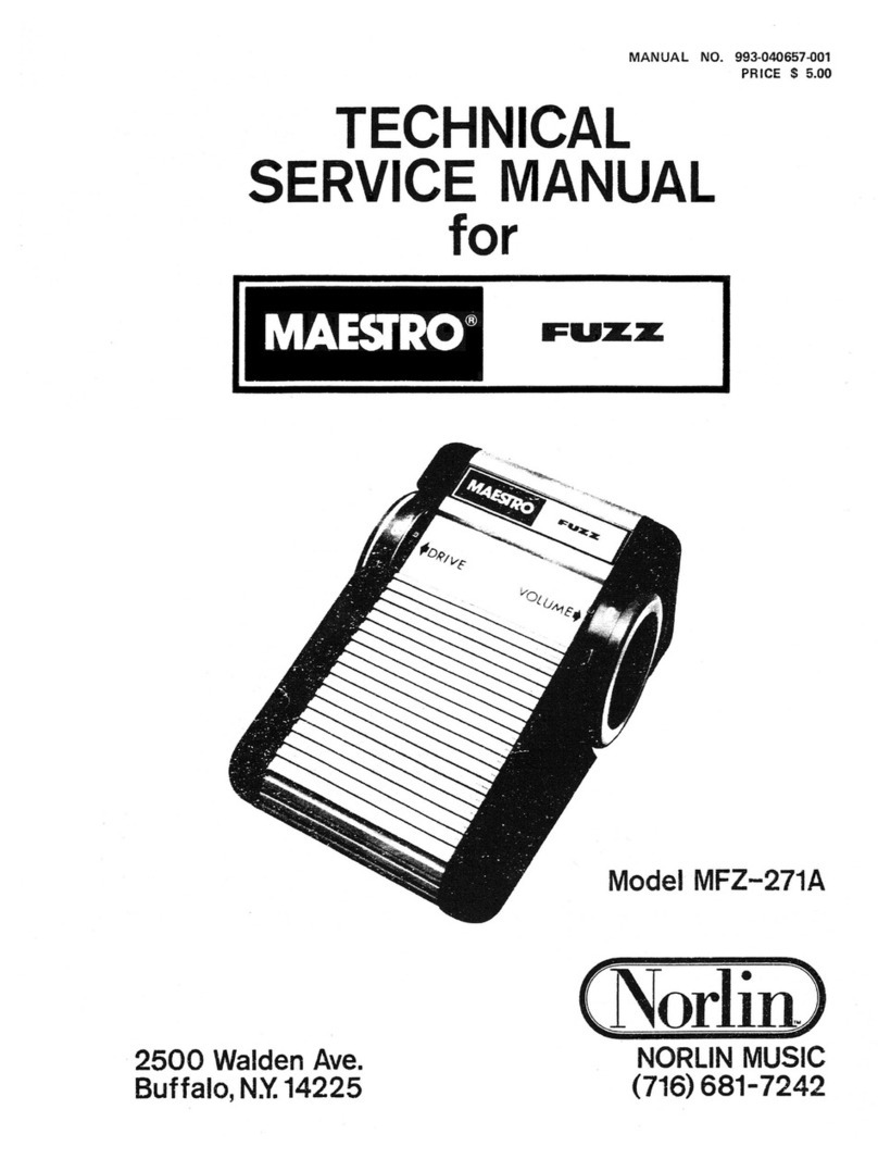
Maestro FUZZ MFZ-271A Operating manual

MANUAL NO. 993-040657-001
PRICE S5.00
TECHNICAL
SERVICE MANUAL
for
MAESTRO
2500 Walden Ave. NORLIN MUSIC
Buffalo, N.Y. 14225 (716)681-7242

INTRODUCTION DISASSEMBLY
This manual provides servicing and parts infor-
mation for Maestro Model MFZ-271A Fuzz, manu-
factured by Moog Music, Inc., 2500 Walden Avenue,
Buffalo, New York 14225. The Maestro Fuzz gener-
ates low order harmonic distortion for guitar, bass
and other electroacoustical music signals. Specifica-
tions for the Maestro Fuzz include:
Input Impedance
Maximum Recommended
Input Level
Output Impedance
Maximum Output Level .
.
Equivalent Input Noise ...
Type of Distortion
Power Requirements
Recommended Battery
Type
Estimated Battery Life ...
1megohm
OdBm
20K ohms (maximum)
+5dBm
-lOOdBm
Low order odd
harmonic
9.0 VDC at
250 microamperes
NEDA 1604
3months
CIRCUIT DESCRIPTION
a) Pull out plungers on battery holder assembly
(1, Figure 1) and remove battery holder assembly.
Disconnect battery (2) if present and remove.
b) Loosen setscrews (3) securing dial assemblies
(4 and 5) by inserting a1/16 inch Allen wrench
through holes in dial assemblies and remove dial
assemblies.
c) Remove nut (6) using ahalf inch nut driver,
lock washer (7), three screws (8) and screw (9) from
each end cap (10) and remove both end caps.
CAUTION
Do not set Maestro Fuzz on its side when
removing second end cap as damage to
rotary pot shaft may result.
d) Position Maestro Fuzz face down and care-
fully slide hinge assembly (11) out of housing
assembly (26) making certain spring (12) around
push switch assembly (17) does not fly off and
remove spring.
The Maestro Fuzz, powered by an internal
9volt battery, generates low order odd harmonic
distortion by using silicon diodes in the feedback
circuit of an operational amplifier. Refer to Figure 3
for the schematic diagram.
Either the fuzz mode or straight guitar is selected
by foot switch SW1. In the fuzz mode, the input
signal from AXE jack J2 is a-c coupled to inverter
IC1A, the output of which feeds DRIVE pot R6.
Since the distortion circuit following R6 is level
sensitive, R6 acts as adistortion amount control.
The distortion circuit consists of IC1B, CR2 and
CR3. Diodes CR2 and CR3 in the feedback path of
IC1B cause symmetrical clipping of the input wave-
form generating the desired distortion. The distorted
signal is a-c coupled to VOLUME pot R9 which
controls the Maestro Fuzz output level. In the
straight mode, SW1 shorts the Maestro Fuzz output
to ground minimizing fuzz circuit bleed-thru and
the input signal is connected directly from AXE
jack J2 to AMP jack Jl.
e) Disconnect three pin connector on printed
circuit board assembly (15) noting black wire on
left side of connector.
f) Remove nuts (13) using ahalf inch nut
driver and flat washers (14) from AXE and AMP
jacks and carefully remove printed circuit board
assembly (15).
g) Remove screw (16), hex nut (18), lock washer
(19) and flat washer (20) and slide out push switch
(22), lock washer and hex ring.
h) Slide foot pads out of their channels if
replacement is required.
TEST AND TROUBLESHOOTING
The Maestro Fuzz requires no tuning or internal
adjustments. When troubleshooting, refer to the
circuit description, schematic diagram, and replace-
ment part lists.
2

a) Visually inspect unit for broken wires,
damaged components, loose connections and other
obvious defects.
b) Make certain unit is connected and operated
according to Owners Manual or instruction label
located on bottom of unit. If possible, check
associated equipment such as cables, battery or
amplifier used with the unit.
c) Connect 9volt dc power source to battery
clip and turn DRIVE and VOLUME pots to
maximum output level.
d) Apply a200 millivolt peak-to-peak sine wave
at afrequency of 500 Hz to AXE jack J2 and observe
dc voltage levels and ac signal levels as shown on
the schematic diagram using an oscilloscope.
NOTE
Ahigh impedance voltmeter (1 megohm
per volt or higher) may be used to
measure dc voltage levels. Note that voltage
levels and waveforms displayed on the
schematic diagram are not absolute values
as readings may vary between units.
e) Once the problem is localized, check the
suspected part by direct substitution if possible.
Otherwise use avoltmeter or oscilloscope to deter-
mine the malfunctioning part.
NOTE
All replacement parts may be obtained
from Moog Music, Inc. However, many
standard electronic parts may be obtained
locally in less time than is required to
receive them from Norlin. When purchasing
replacement parts locally, check the parts
list for proper value, tolerance and rating.
REASSEMBLY
a) Reassemble Maestro Fuzz in reverse order of
disassembly referring to the exploded view (Figure 1
)
and noting the following additions.
b) Finger tighten nuts (13) securing printed
circuit board assembly (15) to housing assembly (26)
to allow printed circuit board assembly to fit into
slots of end caps (10). After both end caps are
installed, tighten nuts (13).
c) Connect three pin connector (24) to printed
circuit board assembly (15) making certain black
wire (pin 1) is on left side of connector at bottom of
printed circuit board.
d) Slip dial assemblies (4 and 5) on rotary pot
shafts (left dial assembly (4) marked “L” between
“9” and “0” and right dial assembly (5) marked “R”
between “9” and “0”) and turn each dial assembly
full counterclockwise and then clockwise.
e) Turn right dial assembly full counterclockwise.
Holding dial assembly steady at “0,” insert small
screwdriver in hole at center of dial assembly and
turn pot shaft full counterclockwise, then approxi-
mately five degrees clockwise to relieve strain on pot
shaft. Tighten setscrew (3).
f) Turn left dial assembly full clockwise. Holding
dial assembly steady at “0,” insert small screwdriver
in hole at center of dial assembly and turn pot shaft
full clockwise, then five degrees counterclockwise to
relieve strain on pot shaft. Tighten setscrew (3).
g) Rotate both dial assemblies making certain
their range is from “0” to “9.”
REPLACEMENT PART LISTS
ORDERING
The following lists specify parts available from
Moog Music, Inc., Customer Service Department,
2500 Walden Avenue, Buffalo, New York 14225,
(716) 681-7242. Please specify the unit name, model,
serial number, part description, electrical reference
designator if applicable and part number when ordering.
3

FIGURE 1MAESTRO FUZZ EXPLODED VIEW
4

MAESTRO FUZZ REPLACEMENTPARTS LIST
INDEX NO. PART NUMBER DESCRIPTION QTY
Figure 1997-040023-001 Maestro Fuzz —
1997-040040-001 Battery Holder Assembly, consisting of: 1
964-040004-001 Batter/ Holder 1
930-040044-001 Plunger 2
930-040043-001 Grommet 2
2Battery, 9Volt, NEDA 1604 Ref
3903-040486-001 Setscrew, No. 6-32 x5/16 Ig, Cup Point (Clad Plate) 2
4997-040041-001 Dial Assembly, Left Side, consisting of: 1
964-040020-001 Dial 1
913-040022-001 Decal, Dial, Left Side 1
913-040046-001 Decal, Disc 1
5997-040041-003 Dial Assembly, Right Side, consisting of: 1
964-040020-001 Dial 1
91 3-040022-003 Decal, Dial, Right Side 1
913-040046-001 Decal, Disc 1
6902-040504-007 Nut, 3/8-32 2
7904-040065-014 Lock Washer, 3/8 1nt 2
8811-040039-010 Screw, Self Tapping, No. 6A x5/8 Ig 6
9811-040032-016 Screw, Self Tapping, No. 6A x1Ig 2
10 968-040009-001 End Cap, Die Cast 2
11 997-040039-001 Hinge Assembly, consisting of: 1
968-040014-001 Hinge Extrusion 1
916-040021-001 Foot Pad 2
905-040045-001 Rivet, Nylon 2
12 975-040128-001 Spring, Compression 1
13 902-040504-007 Nut, 3/8-32 2
14 904-042026-001 Flat Washer, 3/8 2
15 996-040017-001 Printed Circuit Board Assembly (Refer to Figure 2) 1
16 811-040039-010 Screw, Self Tapping. No. 6A x5/8 Ig 1
17 997-040037-001 Push Switch Assembly, consisting of: 1
18 902-040504-006 Hex Nut (15/32 Bushing) 1Ref
19 904-040049-001 Lock Washer (15/32 Bushing) Int. Tooth 2
20 904-040091-001 Flat Washer (15/32 Bushing) 1
21 902-041442-007 Hex Ring (15/32 Bushing) 1Ref
22 960-040042-001 Push Switch, DPDT 1
23 911-040189-001 Lug (No. 6Screw) 1
24 910-041714-003 Housing, Terminal, 3Position 1
25 910-041720-001 Pin 3
26 997-040038-001 Housing Assembly, consisting of: 1
968-040013-001 Housing Extrusion 1
916-040021-001 Foot Pad 2
997-040037-001 Push Switch Assembly (See 17, Figure 1)Ref
997-040039-001 Hinge Assembly (See 11, Figure 1)Ref
27 913-040048-001 Decal, DRIVE-VOLUME 1
28 913-040047-001 Decal, MAESTRO FUZZ 1
29 913-040050-001 Decal, AXE-AMP 1
30 913-040052-001 Instruction Label 1
993-040417-001 Owners Manual 1
5

FIGURE 2PRINTED CIRCUIT BOARD ASSEMBL Y
PRINTED CIRCUIT BOARD ASSEMBLY REPLACEMENTPARTS LIST
INDEX NO.
OR REF DESIG PART NUMBER DESCRIPTION QTY
Figure 2996-040017-001 Printed Circuit Board Assembly, consisting of: —
1980-040016-001 Printed Circuit Board 1
2967-040019-001 Angle Bracket 1
3973-040525-002 Pop Rivet, 1/8 Dia 2
4904-040065-014 Lock Washer, 3/8 Int 2
5976-040793-001 Cable Tie, Small 1
6935-041601-001 Battery Clip, 9Volt 1
Cl 946-026037-103 Capacitor, Polyester, 0.01 uf 1
C2, C5, C6 945-040209-005 Capacitor, Aluminum, Electrolytic, 2.2 uf /50 V3
C3 947-040200-103 Capacitor, Disc, 0.01 uf 1
C4 946-026037-104 Capacitor, Polyester, 0.1 uf 1
C7 947-042020-101 Capacitor, Disc, 100 pf 1
C8 946-040123-224 Capacitor, Polyester, 0.22 uf 1
6

PRINTED CIRCUIT BOARD ASSEMBLY REPLACEMENTPARTS LIST (Cont.j
INDEX NO.
OR REF DESIG PART NUMBER DESCRIPTION QTY
CR1 919-042019-001 Diode, 1N4004 1
CR2.CR3 919-041075-001 Diode, 1N4148, Alt. 1N914 2
ICI 991-041209-001 Integrated Circuit, SN72L022P 1
J1 910-041306-001 Jack, Phone, 1Circuit 1
J2 910-041306-004 Jack, Phone, 2Circuit 1
PI 910-041803-003 Connector, Straight, 3Position 1
R1,R4,R7 852-312105-001 Resistor, 1Megohm, +5%, 1/4 W3
R2,R3 852-312225-001 Resistor, 2.2 Megohms, +5%, 1/4 W2
R5 852-312222-001 Resistor, 2.2K Ohms, +5%. 1/4 W1
R6 925-040033-001 Resistor, Rotary Pot, Linear, 100K Ohms 1
R8 852-312103-001 Resistor, 10K Ohms, +5%, 1/4 W1
R9 925-040032-001 Resistor, Rotary Pot, Audio, 25K Ohms 1
+
TN C2 ACRI ST
2.2/50V 1IN4004
I*;;
T2.2/50V
hi
'50V NOTES
UNLESS OTHERWISE SPECIFIED'
1. ALL RESISTOR VALUES ARE IN OHMS,
+5%, 1/4 WATT.
2. ALL CAPACITOR VALUES ARE IN
MFD (pf )
.
3. WAVEFORMS OBTAINED WITH DRIVE
AND VOLUME POTS AT MAXIMUM.
LIIL.
4. oICI
|T II'F (TOP VIEW)
5. VOLTAGES MEASURED WITH OSCILLO-
SCOPE AND 9VOLT INPUT.
993-040051-001
FIGURE 3MAESTRO FUZZ SCHEMA TIC DIA GRAM
This manual was scanned and restored by Synfo.nl and made available as free download. 7

MAESTRO EUZZTAIN
MODEL MFZT -272A
MANUAL NO. 993-040659-001
Table of contents
Other Maestro Music Pedal manuals

Maestro
Maestro Echoplex EP-3 User manual

Maestro
Maestro COMET CHORUS User manual

Maestro
Maestro FUZZ-TONE FZ-M User manual

Maestro
Maestro DISCOVERER DELAY User manual

Maestro
Maestro ARCAS COMPRESSOR SUSTAINER User manual

Maestro
Maestro INVADER DISTORTION User manual

Maestro
Maestro MARINER TREMOLO User manual

Maestro
Maestro ORBIT PHASER User manual

Maestro
Maestro RANGER OVERDRIVE User manual

Maestro
Maestro MFZ-271A Fuzz Operating manual