WARNING: Risk of re and electric shock
1. Do not cover this product as covering may cause cause the
exible light to overheat and melt or ignite.
2. Do not operate the exible light tightly coiled.
3. Do not route the cord or exible light through walls, ceiling,
doors, windows or any like part of the building structure.
4. Do not submerge exible light in liquids or use the product in
the vicinity of standing water.
5. Do not use if there is any damage to the exible light or cord
insulation.
6. Do not secure the cord or the exible light with staples, nails or
like means that may damage the insulation.
7. Do not install on gates or doors, where subject to exing.
8. Do not install in cabinets, tanks or enclosures of any kind.
FOR OUTDOOR INSTALLATIONS:
9. Ground Fault Circuit Interrupter (GFCI) protection should be
provided on the circuit or outlet.
10. All 120V electrical connections should be carried out by a
qualied electrician.
11. Products should be installed in accordance to these
instructions, current building codes, current Canadian Electrical
Code, or National Electrical Code.
WARNING
DO NOT modify this xture. Any modications may render the
product unsafe and void warranty.
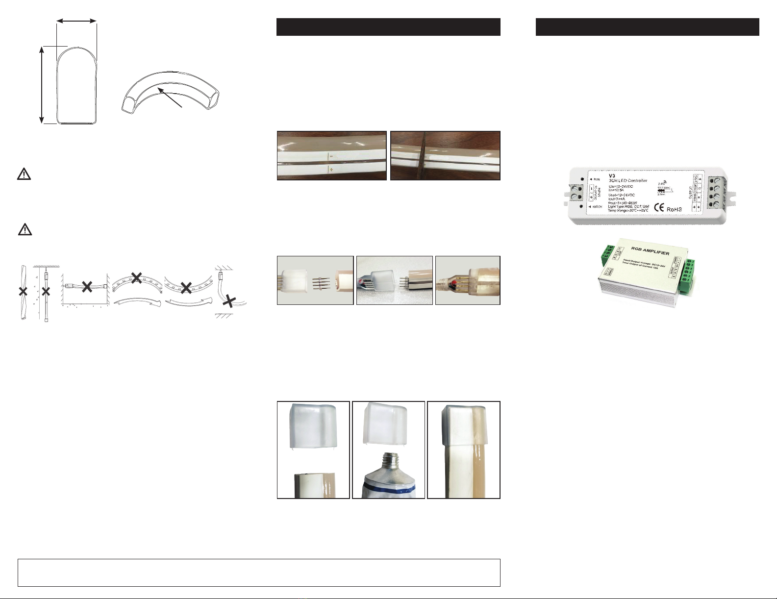
R50mm
15mm
26.5mm
IMPORTANT: Read all instructions in order to
ensure safety and proper installation.
INSTALLATION GUIDE
CONNECTING RGB NEON FLEX TO POWER
RGB Neon Flex runs on 24V DC Class 2 power supply. Use
only power supplies from Magic Lite approved for use with Neon
Flex. Use only extension cords and power cords provided by
Magic Lite. Make sure all the end caps and connections are rmly
seated to preclude the entry of water.
A) Cut Neon Flex to desired length at the cutting marks, using a
sharp knife or cable cutters.
NOTE: RGB Neon Flex is cuttable every 12”.
Cutting anywhere else, will damage the product.
B) Holding the smooth side of the power pins with a pair of
pliers, line up the barbed side of the pins with the four wires of the
exible light. Push barbed pins into the RGB Neon Flex, making
sure to make solid contact with internal wires.
C) Apply silicone glue inside the connector sheath, then push
the cord sheath onto the assembly until fully seated. Wipe any
excess of glue, using a clean towel.
D) Apply silicone glue inside the end cap.
E) Attach the end cap to cover the dead end of the exible light.
Wipe the excess silicone with a dry towel.
F) Leave the assembly to dry for several hours.
NOTE: 120V connections to power supply should be carried
out by a qualied electrician.
CONTROL OF RGB NEON FLEX
NOTE: As RGB Neon Flex is powered by class 2, 24V
DC power supplies, you will need one power supply and
one RGB controller for the rst 40Ft run of RGB Neon
Flex. A signal amplier and additional class 2 power sup-
ply will be required for each additional 40FT (or part of
thereof) of RGB Neon Flex.
NOTE: In outdoor applications, power supplies, controllers and
signal ampliers must be placed in weather proof enclosures,
or to be outdoor rated.
1. Connect power feeds to RGB Neon Flex as per instructions
above.
2. Connect the wires from the power feed connector to output
side of RGB controller. The output side of the controller is marked
(+), R, G, B. Connect black wire to (+), red wire to R, green wire
to G, white wire to B on the controller.
3. Connect the input side of the controller to appropriate size of
24V DC power supply.
NOTE: use only non-dimmable class 2 power supplies
supplied by Magic Lite, for color changing applications.
4. Connect line voltage of the power supply to line voltage.
NOTE: Line voltage connections should be carried out by a
qualied electrician.
INSTALLATION GUIDE
Limited Warranty The warranty applies to the product from the original date of purchase for three (3) years against manufacturing defects. The owner must provide a copy of the
original proof of purchase. The manufacturer’s obligation under this warranty is limited to repairing or replacing the component. It is not related in any way to the cost of connection, the
installation of the replacement parts or cost of transport.
3
WARNING
DO NOT twist, hang vertically, suspend unsupported in the middle
or bend along short side.


