Magikal HYDRO GARDA 18 User manual

TECHINCAL MANUAL
HYDRO GARDA 18
HYDRO GARDA 21
HYDRO GARDA 28
ENGLISH

2
2

3
2
Presentation
The information contained in this manual is intended for qualified personnel only.
The Manufacturer is hereby relieved of any responsibility for damage caused to things and/or persons, due to failure
to comply with this important warning.
The installation and maintenance of these devices is entrusted EXCLUSIVELY to qualified and authorized personnel
operating within the MAGIKAL Technical Assistance Center.
The instructions written by the Manufacturer include the manual and the notices on the machine and on control
elements. During installation, designated personnel must refer to the following laws and regulations:
Ministerial Decree no. 37 - 22.01.2008 (Reorganization of provisions concerning the installation of plants
within buildings)
UNI 10683 (Heat generators powered by wood or other solid fuels. Verification, installation, control and
maintenance)
The laws and regulations in force in the country of use of the Magikal product may provide for higher safety
requirements or identify risks other than those listed in the manual.
The maintenance technician must have read the information in this Technical Manual and in the Use and
Maintenance Manual, as well as be aware of all commands in order to be able to intervene in full compliance with
current safety regulations.
Summary
1. Technical data ..........................................................................................................................................................4
1Installation ...............................................................................................................................................................5
1.1 External air intake and fume exhaust ......................................................................................................................5
1.2 Flue and smoke pipe ................................................................................................................................................5
1.3 Water connection ....................................................................................................................................................7
2Electronic central unit ............................................................................................................................................12
2.1Schema elettrico .............................................................................................. Errore. Il segnalibro non è definito.
2.2 Ambient probe - Ambient thermostat ...................................................................................................................14
3Technical parameters.............................................................................................................................................15
4Errors and remedies...............................................................................................................................................22

4
2
1. Technical data
TECHNICAL DATA
GARDA 18
Garda 21
Garda 23
Nominal
Reduced
Nominal
Reduced
Nominal
Reduced
Thermal input introduced kW
16.4
5.3
21
6.8
27.8
10.07
Rated thermal input kW
15.3
5
19.4
6.4
25.5
9.3
to clearance - kW
1.3
0.7
1.8
1.1
2.5
1.3
to water - kW
14
4.3
17.6
5.3
23
8
Performance -%
93
95
92
94.3
91.8
92.1
Hourly consumption - Kg/h*
3.2
0.9
4.27
1.37
5.63
2
Average fume temperature - °C
110
65
121
65
145
87
Average draft - Pa
12
12
12
Tank capacity - Kg
35
43
53
Autonomy - h*
11
39
11
31
9 ½
26 ½
Heatable volume (nominal) - mᵌ
**
380
460
630
Air intake - Ø
50
50
50
Fume outlet - Ø
80
80
80
Max operation pressure - bar
2.5
2.5
2.5
Voltage - Power frequency
230V / 50 Hz
230V / 50 Hz
230V / 50 Hz
Weight - kg
180
210
230

5
2
2Installation
2.1 External air intake and fume exhaust
For proper operation, the thermo-stove must be positioned in a place where the air necessary for
combustion can flow. Air inflow must take place directly through permanent openings (according to UNI
10683) applied on outside-facing walls having the following features:
Be made in such a way that they can not be obstructed, either from the inside or the outside;
Be protected with grid, wire mesh or suitable guard, provided that it does not reduce the minimum
cross-section of 100 cm.
The minimum volume of the room must not be less than 30 mᶾ.
Air flow can also come from rooms adjacent the installation room, provided that the former are equipped
with an external air intake and NOT used as bedroom and bathroom or, do not present fire hazards, as
storage areas, garages and warehouses for combustible materials may be. Fitting operations must strictly
comply with the provisions of current regulations.
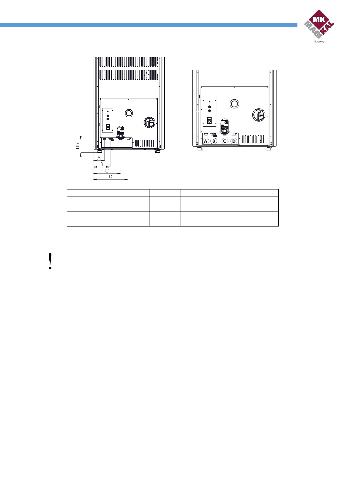
The combustion air inlet of the stove must be made with a Ø50 pipe provided by the customer and fitted in
the rear part.
Installation in bedroom, bathrooms or shower is not permitted, as well as any area in which another
heating appliance without independent inflow (fireplaces, stove, etc.) is already installed
2.2 Flue and smoke pipe
The discharge of combustion by-products must be through the rooftop and take place in 3 different ways:
Using an external flue duct, which must have a minimum internal diameter of 80mm and using
only insulated pipes (double-walled) in stainless steel fixed to the wall (Fig. 8).
By means of a flue, which must have internal dimensions not exceeding 200x200mm; otherwise,
or in case of bad conditions (e.g., cracks, poor insulation, etc), we recommend inserting inside the
barrel a stainless steel pipe of adequate diameter that develops along its entire length up to the
chimney pot (Fig. 9).
By means of a flue or smoke pipe connection which, for proper functioning, immediately
downstream the stove must feature a vertical section of at least 1500mm of height and minimum
horizontal sections having a total width not exceeding 4000mm with an upward slope of no less
than 3% (Fig.10). Moreover, for each 90° bend, we recommend extending the vertical section by 1
m and for each horizontal section, extending the vertical by 2 m. In the case of vertical
developments greater than 7 meters, it is necessary to use pipes with a 100mm internal diameter.
Combustion air inlet
50 Ø.

6
2
These connections, provided for by the UNI 10683 standard, guarantee the discharge of
combustion fumes even in the event of a temporary lack of electrical current. (Fig. 10).
Then ensure that:
There is a minimum draft of at least 10 Pa.
Flue gas exhaust system must always end with a windproof chimney.
Both in the case of an external or internal chimney flue, it is necessary to perform for
periodic checks, while cleaning must be performed annually.
In the event that the smoke outlet pipes pass through flammable material, cover it with
an insulating material (Class A1) of suitable thickness.
E) Combustion air inlet.
F) Ø80 or Ø100 flue ducts
C) “External” insulated double-wall flue pipe L.
min 1500mm
D) “Combustion air” input minimum section 100
cm².
A) “Combustion air” input minimum section 100
cm².
B) Smoke pipe inspection door.

7
2
2.3 Water connection
Available models:
Only residential heating system.
Heating system and domestic hot water production. (This version is only available in the Garda
21 and Garda 28 models).
Model
Components
Heating only
High efficiency 2.5/7 Wilo circulator
Automatic Air Vent
Pressure transducer
Safety valve 2.5 bar
Expansion vessel 8 l. (not illustrated in the figure)
Heating + DHW production
High efficiency 2.5/7 Wilo circulator
Automatic Air Vent
Pressure transducer
Safety valve 2.5 bar
Expansion vessel 8 l. (Not illustrated in the figure)
Flow meter
Motorized valve
Plate heat exchanger
Make sure that the hydraulic system is provided with an appropriately dimensioned closed expansion
vessel, depending on the system itself.
The closed expansion vessel inserted inside the appliance is sized only for its water content.

8
2
Below is the diagram for the hydraulic connection of the product:
Key
Coupling
Garda 18
Garda 21
Garda 28
A - Hot water outlet *
½” - M
-
105
105
B - Cold water inlet
½” - M
-
155
155
C - System return
¾” - M
-
250
250
D - System flow
¾” - M
-
320
320
* The following output is installed only in models with domestic hot water production.
IMPORTANT: Provide the water connection to a heating system capable of dissipating the maximum
rated thermal power of the appliance.
After checking inputs and outputs of water system, in relation to the type of installation to be made,
outfit the system taking into consideration some important issues:
For connection of product to couplings, preferably use flexible hoses to facilitate moving the
heater in case extraordinary maintenance must be performed at a later time.
Complete the connections by interposing shut-off cocks (ball valve cocks), in order to simplify
any extraordinary maintenance.
Connect the outlet of the safety valve to a disposable discharge.
If the model with domestic hot water production is to be installed, consider installing a 6-bar
safety valve.
In order to reduce limestone build-up, which cause pipes to clog, we recommend installing a
water softener if water is particularly hard (above 20°F).
2.3.1 Domestic hot water function
The production of domestic hot water is automatically managed by the components in the water kit
illustrated above.
The kit is fitted with a flow switch that detects the water flow for domestic use, which, in turn, allows the
3-way motorized valve to exchange with the plate heat exchanger contained in the kit.
At this moment, therefore, the water from the heating unit is pushed by the circulation pump through the
plate heat exchanger, thus producing hot water for domestic use.
To allow production of domestic hot water, the temperature in the heating unit must be at least 55° (Th20);
after determining flow and temperature suitability of the machine, the control unit sets the temperature

9
2
within the heating unit to 70° (Th21 - Ih21) and combustion is regulated on the basis of this value. When
there is no longer any request, the Sanitary Function ends at timer expiration (T68) set to 20sec by default,
repositioning the heating unit thermostat to the original temperature.
It is also advisable to use the sanitary function with heating unit temperatures not below 65°, in order to
optimize production of hot water and avoid the risk of cold outflow.
2.3.2 System configuration
Symbols
Component
Presence within the product of components described according to
the model ordered
Version: Only system heating
Version: System heating + DHW
production
P1
Boiler body circulator
PRESENT
PRESENT
P2
Circulator or solenoid
valve
NOT PRESENT
PRESENT
FL
Flow meter
NOT PRESENT
PRESENT
S1
Boiler probe
PRESENT
PRESENT
S2
Puffer probe
NOT PRESENT
NOT PRESENT
All components not present inside can be added during installation, followed by a correct electrical connection and
configuration that will be illustrated in the following chapters.
To set the system configuration more suited to the type of installation, simply change parameter P26 in the System
Menu, in the Default Settings section.
Parameter variation
System type
P26 = 0
Configuration 0
P26 = 2
Configuration 2
P26 = 4
Configuration 4
The operating logics for the various types of system configuration will be illustrated below.
Configuration 0 - P26 = 0 - Factory default
System combined with gas boiler in the heating version only.
To connect the thermo-stove to another (gas-operated) boiler to a closed-vessel water system, it is
advisable to install a Plate Heat Exchanger, keeping the water circuits of the two heat generators separate.

10
2
The operation of the Garda thermo-stove is a priority compared to the work of the combined boiler, since
the most economical fuel is pellet-operated.
The control unit is able to automatically manage the work between the two machines by connecting a 3-
way motorized valve.
In this case, the Boiler Probe (S1) detects the temperature of the machine body of the thermo-stove; once
the probe reaches the temperature of 50° (Th19), circulator P1 of the thermo-stove starts to exchange with
the system and the motorized valve P2 with thermostat set at 50° (Th56) opens the circuit between system
and thermo-stove.
Vice versa, when the temperature read by the S1 probe is lower than 50° (Th56), the 3-way motorized valve
(P2) exchanges, allowing the gas boiler to heat the domestic system.
Independent-operated system with DHW production.
System heating logic:
The thermo-stove is powered by pellets, the only heat generator for the heating and sanitary system (or, at
minimum, management between the thermo-stove and the gas boiler is carried out manually by the end
user).
Therefore, probe S1 detects the temperature in the boiler body and regulates the start of the circulator P1
once the machine reaches 50° (Th19).
DHW production logic:
The thermo-stove features a flow switch (FL) that detects the request of the hot water for domestic use;
with the operation of the flow switch, the electronic control unit automatically diverts the flow to the plate
exchanger through the motorized valve (P2) for the instantaneous production of domestic hot water.
Furthermore, as the thermo-stove detects the DHW request, it reaches its temperature of 70° (Th21-Ih21)
to guarantee constant production of hot water.
In this case, if the installed thermo-stove also produces domestic hot water, flow switch, plate exchanger
and motorized valve are already present inside the product.
Configuration 2 - P26 = 2 - Sanitary Boiler
To prepare the thermo-stove for heating a storage cylinder for sanitary use, also requires performing the
following operations:
Enter the System Menu - Default Settings, and set Technical Parameter P26 to 2.
Set the temperature you wish for water inside the Boiler (Factory settings 65°), in the Puffer
Thermostat, in the User Menu - Heating Management - Puffer Thermostat.
Connect an optional probe (NTC 10K @ 25°C) to terminals 34 and 35 of the electronic control
unit terminal board and firmly insert it into a boiler to allow the thermo-stove control unit to
detect the temperature inside the boiler.

11
2
Connect the terminals of the 3-way motorized valve P2 to the Aux1 output of the electronic
control unit
System heating logic:
By setting parameter P26 = 2, you choose the configuration shown in the figure above.
The circulator is active if the water temperature in the boiler (S1) exceeds the value of the Th19 thermostat.
To avoid water freezing, the circulator is activated if water temperature in the boiler drops below 5° (Th18).
If the water temperature in the boiler (S1) exceeds the 80° threshold (Th21), the P1 circulator is always
active for safety reasons.
DHW production logic:
The valve (P2) diverts the thermo-stove inlet towards the Sanitary Boiler if the water temperature in the
boiler does not exceed 75° (Th58) and the boiler water temperature (S1) exceeds 55° (Th20) .
For safety reasons, if the boiler water temperature (S1) exceeds the value of the Th21 thermostat, the valve
switches to the heating system.
Note: By setting the Summer mode (Domestic hot water production only), when the water temperature
inside the boiler reaches 65°C (Thermostat Puffer), the heater is in Standby mode.
When water temperature inside the Boiler falls below 63°C (Puffer temperature - Ih58), the thermo-stove
comes out of the Standby, thus igniting.
Configuration 4 - P26 = 4 - Accumulation Puffer
To prepare the thermo-stove for heating an accumulation puffer, it is also necessary to perform the following
operations:
Enter the System Menu - Default Settings, and set Technical Parameter P26 to 4.
Set the temperature you wish for water inside the Puffer (Factory settings 65°), in the Puffer Thermostat,
in the User Menu - Heating Management.
Connect an optional probe (NTC 10K @ 25°C) to terminals 34 and 35 of the electronic control
unit terminal board and firmly insert it into a boiler to allow the thermo-stove control unit to
detect the temperature inside the boiler.
Connect the second P2 circulation pump to the Aux 1 output of the electronic control unit,
specifically to terminals 22 and 24.

12
2
System heating logic:
If the temperature in boiler S1 is greater than the Pump activation thermostat equal to 50° (Th19), the
system heats the water of the Puffer if the difference between S1 and S2 is greater than 5°C (Th57).
If the water temperature in the boiler (S1) exceeds the 80° threshold (Th21), the P1 circulator is always
active for safety reasons.
Circulator P2 is activated when the puffer exceeds 60° (Th59).
2.3.3 System filling
Do not operate the thermo-stove for any reason if the system is not filled with water, as the product may be
damaged irreparably.
To fill the system, proceed as follows:
If the installed version also features production of domestic hot water, load the system from the black
knob located under the product water kit; otherwise, if the model is only for heating, load the system
from the return through the filling unit placed on the system itself.
Open all the radiator vents so as to avoid air pockets in the system, which would then hinder the normal
water circulation.
Purge the air through the vent valves installed in the system and in the radiators.
Check that the vent in the machine body is loose, then remove the top cover using the special lever (used
to open the loading door) and slightly unscrew the cap placed on the automatic vent valve in the delivery
pipe towards the right side of the product.
Using the electronic control unit and check the heating circuit pressure. From the main display screen,
double-click the arrow at the bottom right (↓) and check that the pressure read is about 1000 mbar with
the system at room temperature.
Perform an air release from the radiator valves.
Check that the system pressure is stable, checking for any water leaks.
If the pressure is stable and no water leaks, the product is hydraulically ready.
3Electronic central unit
In addition to performing all management and boiler operation control functions, the electronic control unit of the
thermo-stove is also equipped as standard with the following features:
Antifreeze function (automatic activation of the circulator with water temperature lower than or equal to
5°);
Circulator or solenoid valve anti-lock function (automatic activation of the circulator and of the solenoid
valve for 20 seconds every 7 days of inactivity);
Automatic management of domestic hot water production only in models that provide it;
Management of a possible storage Boiler for Healthcare use;
Management of a possible storage Puffer for heating and sanitary purposes;
Automatic work management with a combined (Gas-operated) boiler.
Input for connecting an additional room thermostat.
Serial port (RS232) for connecting a GSM modem (Wi-Fi) and for updating the control unit.

13
2
+V 40
GND 41
S7 42
Display LCD
+25
- 26
M
N
B
Auger
Pump 1
Motorized
Valve
B
R
Encoder flue
extractor
3.1 Circuit diagram
Motorized valve and flow switch will be present and connected only in versions with domestic hot water
production.
RS485
RS232
S2 27
GND 28
GND 29
S3 30
GND 31
S4 32
+V 33
GND 34
S5 35
E36
+V 37
S6 38
GND 39
24 FON
23 FOFF
22 N
21 N.O.
20 N.C.
19 COM
18 F
17 N
16 F
15 N
14
13
12
11
10 F
9 N
8FF
7 NN
6FF
5 NN
4FF
3 NN
2N
1 L
LINEA
V1
V2
P/V3
R
H1
H2
C
↓
↓
AUX 2
AUX 1
Line
(230V 50Hz)
Cartridge heaters
Ait Vent
(Optional)
Fume extractor
Pressure
switch
Safety
Thermostat
R
M
N
Pressure
Transducer
Probe Puffer
(Optional)
Boiler Probe
(Garda)
Thermocouple
IN 1
IN 2
IN 3
IN 4
IN 5
IN 6
IN 7
CN1
N
Ambient probe -
Thermostat
Flow switch

14
2
3.2 Ambient probe - Ambient thermostat
To configure the work of the thermo-stove with an ambient probe or room thermostat, parameter A19 must be
changed, if in clamps 27 and 28 of the printed circuit board is connected to:
Ambient probe (as installed by the factory) set A19 = 1 (already set in Default).
The supplied NTC 10K probe, the reading range is 0 ÷ 50°C with the accuracy of 1°C. If the probe is
disconnected, a temperature value of 0°C will be read; in the case of short circuit, the temperature
detected will be maximum (50°C).
Or, if you wanted to connect a:
Ambient thermostat set A19 = 0
By setting parameter A01 in the System Menu, the ambient probe or thermostat can be operated according to
the user's needs.
If A01 = 0
Ambient probe/thermostat not reached: the System goes into Check-up status.
Ambient probe/thermostat reached: the System goes into Shut-off status.
If A01 = 1 (default setting)
Ambient probe/thermostat not reached: the System goes into Normal status.
Ambient probe/thermostat reached: the System goes into Modulation status.
If A01 = 2
Ambient probe/thermostat not reached: the System goes into Normal status.
Ambient probe/thermostat reached: the System goes into Standby status.
If A01 = 3
Ambient probe/thermostat not reached: The system reactivates Pump 1.
Ambient probe/thermostat reached: if the boiler water temperature exceeds the value of the Th19
thermostat (50°C), the system blocks Pump 1 until reaching the Th21 thermostat (80°C).
If A01 = 4
Ambient probe/thermostat not reached: the System reactivates the system pump and goes into Normal
mode.
Ambient probe/thermostat reached: the System goes into Standby mode and blocks Pump 1, as in case
3.
If A01 = 5
Ambient probe/thermostat not reached: Heating vent operates properly.
Ambient probe/thermostat reached: if A11 = 0, the heating vent is switched off, if A11 = 1 goes to Power
1.

15
2
4Technical parameters
The following are the default technical parameters already prepared in the printed circuit board.
To make changes to parameters, access through the Display, select the System Menu and enter the password:
6593.
Auger
Parameter
Description Function
Garda
18
Garda
21
Garda
28
U.M
C01
Auger time ON at Ignition
-
0.5
0.6
sec
C02
Auger time ON at Stabilization
-
1.1
0.9
sec
C03
Auger time ON at Power 1
-
1.6
1.7
sec
C04
Auger time ON at Power 2
-
1.9
2.2
sec
C05
Auger time ON at Power 3
-
2.3
2.7
sec
C06
Auger time ON at Power 4
-
2.6
3.2
sec
C07
Auger time ON at Power 5
-
3.0
3.8
sec
C10
Auger time ON at second Ignition
-
0.0
0.0
sec
C11
Auger time ON at Modulation
-
1.5
1.6
sec
P05
Total Time Auger Period
7.0
7.0
7.0
sec
P15
Value of the correction step
5
5
5
%
P27
Minimum Time Auger ON
0.0
0.0
0.0
sec
Fume fan 1
Parameter
Description Function
Garda
18
Garda
21
Garda
28
U.M
U01
Extractor Speed at Ignition
-
2100
2300
rpm
U02
Extractor Speed at Stabilization
-
2000
2200
rpm
U03
Extractor Speed at Power 1
-
1890
1720
rpm
U04
Extractor Speed at Power 2
-
2000
1980
rpm
U05
Extractor Speed at Power 3
-
2150
2230
rpm
U06
Extractor Speed at Power 4
-
2240
2340
rpm
U07
Extractor Speed at Power 5
-
2370
2520
rpm
U10
Extractor Speed at Second Ignition
-
1000
1000
rpm
U11
Extractor Speed at Modulation
-
1830
1690
rpm
U12
Extractor Speed at Standby
-
2500
2500
rpm
P23
Extractor Speed at Shutoff
-
2700
2700
rpm
P14
Minimum speed at Combustion
-
530
530
rpm
P30
Maximum speed at Combustion
-
2800
2800
rpm
P16
Value of correction step
5
5
5
%

16
2
Heating fan (Optional)
Parameter
Description Function
Garda
18
Garda
21
Garda
28
U.M
F01
Power 1
130
130
130
Volt
F02
Power 2
150
150
150
Volt
F03
Power 3
180
180
180
Volt
F04
Power 4
200
200
200
Volt
F05
Power 5
230
230
230
Volt
P06
Heating management: 1=Heating power as combustion
power; 2=Heating power proportional to flue gas
temperature; 3=Heating power proportional to room
temperature
3
3
3
nr
Thermostats
Parameter
Description Function
Garda
18
Garda
21
Garda
28
U.M
Th01
Thermostat at stove off
50
50
50
°C
Th02
Glowplug deactivation thermostat
55
55
55
°C
Th03
Thermostat for pre-switch off due to lack of flame
45
45
45
°C
Th05
Heating fan activation thermostat
70
70
70
°C
Th06
Thermostat for passage from Stabilization to Variable-phase
Step
50
50
50
°C
Th07
Fume modulation
180
180
180
°C
Th08
Fume safety
200
200
200
°C
Th09
Ignition Bypass Thermostat
100
100
100
°C
Th18
Anti-freeze Thermostat
5
5
5
°C
Th19
Pump P1 activation thermostat
50
50
50
°C
Ih19
Pump P1 activation Thermostat Hysteresis
2
2
2
°C
Th20
Sanitary 1 Thermostat
55
55
55
°C
Th21
Sanitary 2 Thermostat
80
80
80
°C
Ih21
Sanitary 2 Thermostat Hysteresis
10
10
10
°C
Ih24
Boiler Thermostat Hysteresis
3
3
3
°C
Th25
Boiler Safety Thermostat
90
90
90
°C
Th26
Boiler Thermostat Minimum range
50
50
50
°C
Th27
Maximum Boiler Thermostat Range
75
75
75
°C
Th28
Fume Temperature Control in Standby
90
90
90
°C
Ih33
Ambient Thermostat Hysteresis
1
1
1
°C
Th56
Thermostat-controlled Output Thermostat
50
50
50
°C
Ih56
Thermostat-controlled Output Thermostat Hysteresis
1
1
1
°C
Th57
Boiler Probe - Boiler Probe Differential
5
5
5
°C
Ih57
Differential Thermostat Hysteresis
1
1
1
°C
Ih58
Boiler Thermostat Hysteresis
3
3
3
°C
Th59
Pump P2 activation Thermostat (only if P26=4)
60
60
60
°C
Ih59
Pump P2 activation Thermostat Hysteresis (only if P26=4)
2
2
2
°C
Th60
Thermostat-controlled Output 2 Thermostat
50
50
50
°C
Ih60
Thermostat-controlled Output 2 Thermostat Hysteresis
1
1
1
°C

17
2
Shutoff Thermostats
By setting the temperature value for each operating power, if the fume temperature falls below
the value set for the corresponding power in operation, the system goes into Shutdown with
Er03.
Parameter
Function Description
Garda
18
Garda
21
Garda
28
U.M
Th35
Shutoff at Power 1
45
45
45
°C
Th36
Shutoff at Power 2
45
45
45
°C
Th37
Shutoff at Power 3
45
45
45
°C
Th38
Shutoff at Power 4
45
45
45
°C
Th39
Shutoff at Power 5
45
45
45
°C
Th40
Shutoff at Power 6 (not used)
45
45
45
°C
Th43
Shutoff at Modulation Power
45
45
45
°C
Time Menu
Parameter
Function Description
Garda
18
Garda
21
Garda
28
U.M
T01
Speed at Ignition
-
20
20
sec
T02
Glowplug preheat
-
60
60
sec
T03
Pre-charge at Ignition
-
63
86
sec
T04
Fixed Ignition
-
120
120
sec
T05
Variable Ignition
-
400
400
sec
T06
Stabilization
-
300
315
sec
T07
Periodic cleaning repetition
-
20
20
min
T08
Periodic cleaning duration
-
30
30
sec
T09
High Voltage 1 Safety Delay
-
5
5
sec
T10
High Voltage 2 Safety Delay
-
120
120
sec
T11
Delay exit in Standby
-
10
10
sec
T13
Minimum duration of Shutoff phase
-
180
180
sec
T14
Pre-shutoff
-
120
120
sec
T15
Safe Shutoff
-
60
60
sec
T16
Final cleaning at Shutoff
-
240
240
sec
T17
Power upgrade
-
10
10
sec
T18
Ignition power upgrade
-
60
60
sec
T22
Delayed entry in Standby
-
10
10
sec
T23
Fuel tank filling timer (Not used)
-
10
10
sec
T24
Waiting for pellet loading in the tank (Not used)
-
20
20
sec
T27
Pallet safety valve deactivation delay (Not used)
-
30
30
sec
T29
Auger turned off at Preload
-
120
120
sec
T30
Exchanger Cleaning Engine Working time (Not used)
-
30
30
sec
T31
Exchanger Cleaning Interval (Not used)
-
2
2
min
T32
Waiting time for brazier maintenance in Standby
-
30
30
min
T33
Operation time for brazier maintenance in Standby
-
20
20
sec
T34
Auger activation time in case of flame return
-
0
0
sec
T40
Auger activation delay (if set)
-
0
0
sec
T41
Pump P1 working time if T42 has expired
-
30
30
sec
T42
Maximum inactivity time of Pump P1 and Pump P2 or
solenoid valve
-
120
120
hours
T43
Timer to switch from Modulation to Standby if boiler
temperature is> (Boiler Thermostat + D23) and A13 = 1
-
90
90
sec
T46
Valve working time if T42 has expired
-
90
90
sec

18
2
T57
Minimum duration of Standby phase
-
30
30
sec
T58
Final brazier cleaning in Standby
-
90
90
sec
T66
Run time before switching to Block
-
1200
1200
hours
T67
System running time before the message Cleaning appears
-
0
0
hours
T68
Delay of restoration of original value of Boiler Thermostat
in case of ceased domestic water request
-
20
20
sec
T69
Delay in activation of maximum Heating Fan if fume
temperature > Th07
-
30
30
sec
T75
Cleaning motor 2 working time (not used)
-
30
30
sec
T76
Cleaning motor 2 pause time (not used)
-
2
2
min
T85
Maximum time for limit switch opening (not used)
-
10
10
sec
T86
Brazier Cleaning Motor working time (not used)
-
60
60
sec
T87
Brazier Cleaning Motor pause time (not used)
-
2
2
min
T88
Maximum time of power failure for the system to return to
its original state
-
60
60
sec
T89
Maximum time of power failure for the system to return to
its Power-up Recovery
-
30
30
min
Default Settings Menu
Parameter
Function Description
Garda
18
Garda
21
Garda
28
U.M
P02
Maximum number of power-up attempts
1
1
1
no.
P03
Number of operating powers
5
5
5
no.
P04
Number of recipes
1
1
1
no.
P09
Pellet Level Sensor Configuration (0= N.C. sensor input; 1=
N.O. sensor input)
0
0
0
no.
P20
Select Pressure Sensor
1
1
1
no.
P25
0= Extractor Without Encoder; 1= Extractor with Encoder; 2=
Extractor with Encoder with automatic passage in P25= 0 in
case of encoder signal failure (alarm Er07)
1
1
1
no.
P26
Hydraulic system configuration (see page 9)
0
0
0
no.
P66
Enabling RS485
0
0
0
no.
P75
Input 3 Management
5
5
5
no.
Configurable outputs
It is possible to configure outputs V2 (pin 5-6), P/V3 (7-8), Aux1 (22-23-24) Aux2 (19-20-21) and
Aux3 (46-47), depending on the value of their respective management parameters (P44, P48, P50
and P51)
Parameter
Function Description
Garda
18
Garda
21
Garda
28
U.M
P44
V2
0
Output V2 Disabled
0
no.
1
Output V2 for Safety Valve/Auger2
3
Output V2 for Output under Thermostat
11
Output V2 for Error Alarm
15
Output V2 for Pump 2 or solenoid valve
27
Output V2 for Output under Thermostat 2
P48
AUX2
0
Output AUX2 Disabled
14
no.
14
Output AUX2 Pump1
P50
P/V3
0
Output P/V3 Disabled
6
no.
1
Output P/V3 for Safety Valve/Auger2
3
Output P/V3 for Output under Thermostat
6
Output P/V3 for Warm Air Fan
11
Output P/V3 for Error Alarm

19
2
15
Output P/V3 for Pump 2 or solenoid valve
27
Output P/V3 for Output under Thermostat 2
P51
AUX1
0
Output AUX1 Disabled
15
no.
1
Output AUX1 for Safety Valve/Auger2
3
Output AUX1 for Output under Thermostat
12
Output AUX1 for Summer/Winter Valve
15
Output AUX1 for Pump 2 or solenoid valve
27
Output AUX1 for Output under Thermostat 2
Output configurability legend:
Output disabled: In this case, the output is disabled so it does not send any signal.
Output for Safety Valve/Auger2: If used as Safety Valve, the Auger will only activate
when timer T40 expires; If used as Auger2, it will deactivate only at the expiration of
timer T27.
Output under Thermostat: The output is managed by thermostat Th56; above this value,
the output is powered.
Output for Warm Air Fan: The output manages the work of a fan for the production of
hot air in the environment
Output for Summer/Winter Valve: If P51=12 a voltage is guaranteed between pins 22-24
in Summer mode, and between pins 22-23 in Winter mode.
Output for Pump 2 or solenoid valve: The output manages the Solenoid valve or Pump2
of the selected Hydraulic system.
Output under Thermostat 2: The output is managed by thermostat Th60; above this
value, the output is powered.
Authorizations Menu
Parameter
Function Description
Garda
18
Garda
21
Garda
28
U.M
A01
0
Ambient thermostat/probe for Power-up/Shutoff
1
no.
1
Ambient thermostat/probe from Normal/Modulat.
2
Ambient thermostat/probe for Normal/Standby
3
Ambient thermostat/probe blocks Pump1 until
thermostat Th21 is reached
4
Ambient thermostat/probe blocks for Normal/Standby
and blocks Pump 1 until thermostat Th21 is reached
5
Ambient thermostat/probe stops the warm air fan or
sends it to the minimum
A03
0
Warm air fan off in Standby
1
no.
1
Warm air fan off at Power 1 in Standby
A06
0
Modulation uses Power 1
1
no.
1
Modulation uses Modulation Power
A07
0
External timer for Power-up/Shutoff
0
no.
1
External timer for Normal/Modulation
2
External timer for Normal/Standby
3
External timer blocks Pump 1 until thermostat Th21 is
reached
4
External timer between Normal/Standby
A08
0
Warm Air Fan in disabled Power-up:
0
no.
1
Warm Air Fan in enabled Power-up:
A10
0
Switch-on command from Power-off sends to Power-
up Recovery
1
no.

20
2
1
Switch-on command from Power-off sends to Check-
up
A11
0
Warm Air Fan stops if Ambient temperature >
Ambient thermostat/sensor
0
no.
1
Warm air fan at Power 1 if Ambient temperature >
Ambient thermostat/sensor
A13
0
For boiler temperature> Boiler thermostat, the system
goes into Modulation
1
no.
1
For boiler temperature > Boiler thermostat, the
system goes first to Modulation and then, if boiler
temperature > (Boiler Thermostat + D23), goes into
Standby-Shutdown.
A14
0
Error management Sensor Pressure disabled
1
no.
1
Error management Sensor Pressure enabled
A16
0
Normal combustion power management
1
no.
1
Combustion power management with delay
A19
0
Ambient Thermostat Selection
1
no.
1
Ambient Probe Selection
A26
0
Exit from Standby if the activation conditions no
longer exist
1
no.
1
Exiting Standby if activation conditions no longer exist,
at the end of Timer T13 and if fume temperature is
lower than thermostat Th28
A27
0
In Standby, the system switches off the brazier
0
no.
1
In Standby, the system perform maintenance on the
brazier
A28
0
Auger brake not enabled
1
no.
1
Auger brake enabled
A29
0
If the system is in Standby for External Thermostat or
Ambient Probe, it does not activate for domestic
water request
1
no.
1
If the system is in Standby for External Thermostat or
Ambient Probe, it activates for domestic water
request
A32
0
Internal timer for Power-up/Shutoff
0
no.
1
Internal timer for Normal/Modulation
2
Internal timer for Normal/Standby
3
Internal timer stops the system pump until thermostat
Th21 is reached
4
Internal time for Normal/Standby and Pump Block
until thermostat Th21 is reached
A53
0
System in Block with Er15 if there is no voltage for
more than T89 minutes
0
no.
1
System in Power-up Recovery if there is no voltage for
more than T89 minutes
A61
0
Periodic cleaning enabled only in Normal mode
1
no.
1
Periodic cleaning enabled also in Modulation mode
This manual suits for next models
2
Table of contents
Popular Stove manuals by other brands

alchemy
alchemy RB700-MKIII Installation & user manual

Ariterm
Ariterm EKERUM Installation and operating instructions

GALLERY
GALLERY HELIOS Installation and operating instructions

Drolet
Drolet AC02080 Technical data

wallas
wallas Safe Flame 800 installation instructions

Masport
Masport MONTEREI installation instructions