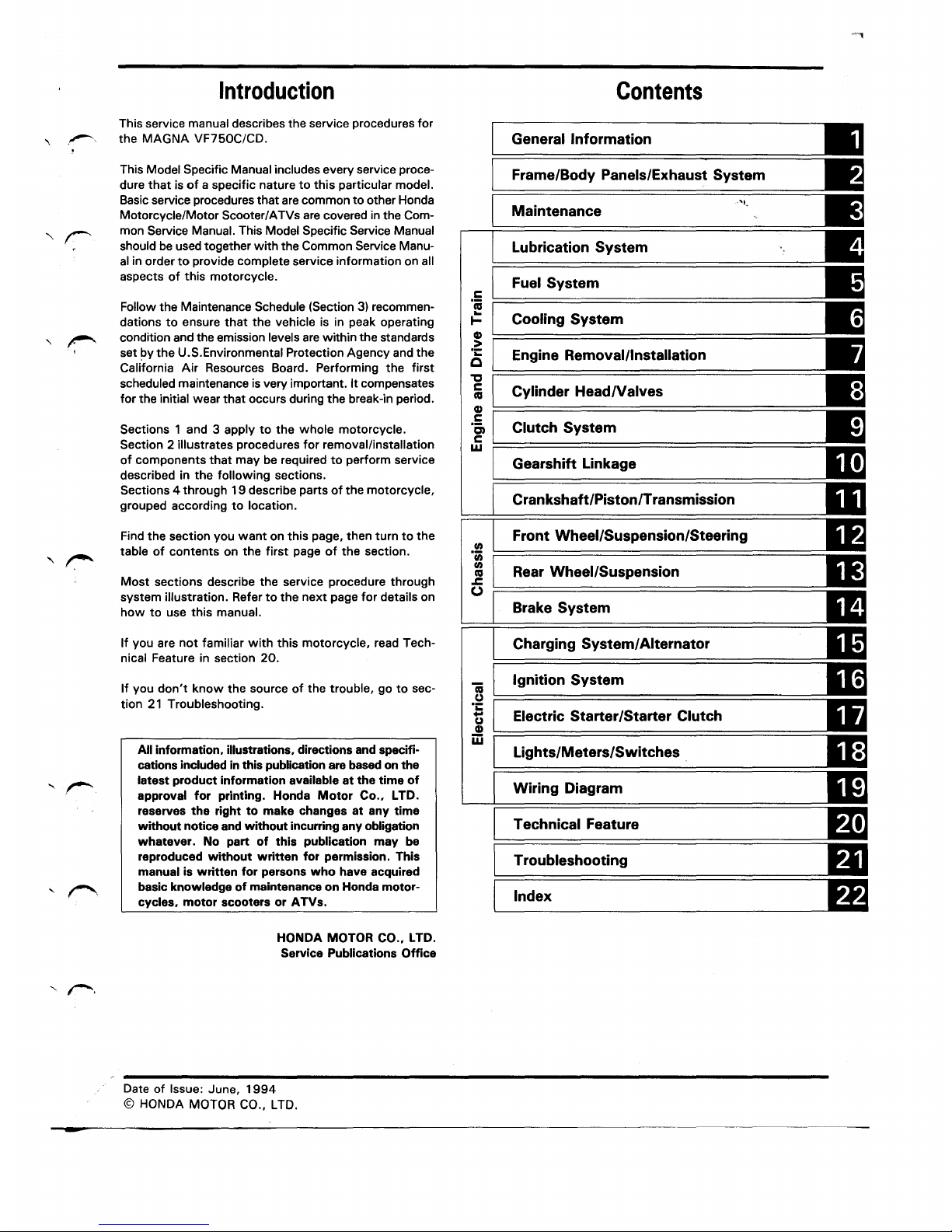
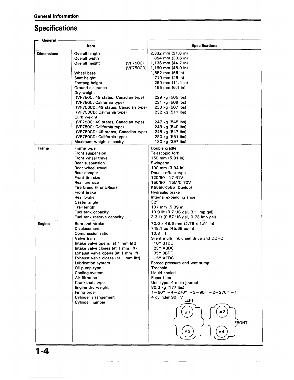
manuals.online logo
Brands
  1. Home
  2. •
  3. Brands
  4. •
  5. Magna
  6. •
  7. Motorcycle
  8. •
  9. Magna VF750C User manual

Magna VF750C User manual

This manual suits for next models

1

Popular Motorcycle manuals by other brands

MV Agusta Brutale 675 Workshop manual

MV Agusta

MV Agusta Brutale 675 Workshop manual

APRILIA RSV MILLE - PART 1 1999 User manual content

APRILIA

APRILIA RSV MILLE - PART 1 1999 User manual content

Royal Enfield Himalayan 2018 owner's manual

Royal Enfield

Royal Enfield Himalayan 2018 owner's manual

SSR Motorsports Lazer5 owner's manual

SSR Motorsports

SSR Motorsports Lazer5 owner's manual

MOTO GUZZI 2005 Griso 1100 Use and maintenance book

MOTO GUZZI

MOTO GUZZI 2005 Griso 1100 Use and maintenance book

KTM 85 SX 19/16 owner's manual

KTM

KTM 85 SX 19/16 owner's manual

Beta Motorcycles XTRAINER 250 2T EUROPA 2022 manual

Beta Motorcycles

Beta Motorcycles XTRAINER 250 2T EUROPA 2022 manual

OHVALE GP-0 Use & maintenance

OHVALE

OHVALE GP-0 Use & maintenance

Yamaha Star XV19CTSZ 2009 owner's manual

Yamaha

Yamaha Star XV19CTSZ 2009 owner's manual

KTM 350 XCF-W USA owner's manual

KTM

KTM 350 XCF-W USA owner's manual

HYOSUNG ST7 owner's manual

HYOSUNG

HYOSUNG ST7 owner's manual

Husqvarna FC 250 2016 owner's manual

Husqvarna

Husqvarna FC 250 2016 owner's manual

Yamaha TDR125 owner's manual

Yamaha

Yamaha TDR125 owner's manual

APRILIA ETV MILLE CAPONORD - PART1 02-2001 manual

APRILIA

APRILIA ETV MILLE CAPONORD - PART1 02-2001 manual

KTM Freeride E-XC 2021 owner's manual

KTM

KTM Freeride E-XC 2021 owner's manual

Fantic Enduro 125 user manual

Fantic

Fantic Enduro 125 user manual

Ducati Supersport 750 desmodue owner's manual

Ducati

Ducati Supersport 750 desmodue owner's manual

MV Agusta 2008 F4 312RR 1078 Workshop manual

MV Agusta

MV Agusta 2008 F4 312RR 1078 Workshop manual

manuals.online logo
manuals.online logoBrands
  • About & Mission
  • Contact us
  • Privacy Policy
  • Terms and Conditions

Copyright 2025 Manuals.Online. All Rights Reserved.

r'··
Introduction
This service manual describes the service procedures for
the
MAGNA
VF750C/CD.
This Model Specific Manual includes every service proce-
dure
that
is
of
a specific nature
to
this
particular model.
Basic service procedures
that
are common
to
other Honda
Motorcycle/Motor Scooter/ATVs
are
covered in the Com-
mon Service Manual. This Model Specific Service Manual
should
be
used together
with
the Common Service Manu-
al
in order
to
provide complete service information on all
aspects
of
this motorcycle.
Follow the Maintenance Schedule (Section 3) recommen-
dations
to
ensure
that
the
vehicle is in peak operating
condition and the emission levels
are
within the standards
set by
the
U.S.Environmental Protection Agency and the
California
Air
Resources Board. Performing
the
first
scheduled maintenance
is
very important.
It
compensates
for
the initial wear
that
occurs during
the
break-in period.
Sections 1 and 3 apply
to
the
whole
motorcycle.
Section 2 illustrates procedures
for
removal/installation
of
components
that
may be required
to
perform service
described in
the
following
sections.
Sections 4 through
19
describe parts
of
the
motorcycle,
grouped according
to
location.
Find
the
section you
want
on
this
page, then
turn
to
the
table
of
contents
on
the
first
page
of
the
section.
Most
sections describe the service procedure through
system illustration. Refer
to
the
next
page
for
details on
how
to
use
this
manual.
If
you are
not
familiar
with
this
motorcycle,
read Tech-
nical Feature in section 20.
If
you
don't
know
the
source
of
the
trouble, go
to
sec-
tion
21
Troubleshooting.
All information, illustrations, directions and specifi-
cations included in this publication are based on the
latest
product
information available
at
the
time
of
approval
for
printing. Honda
Motor
Co.,
LTD.
reserves
the
right
to
make changes
at
any
time
without
noticeand
without
incurring any obligation
whatever.
No part
of
this
publication
may
be
reproduced
without
written
for
permission. This
manual is
written
for
persons
who
have acquired
basic knowledge
of
maintenance
on
Honda
motor-
cycles,
motor
scooters
or
ATVs.
HONDA MOTOR CO., LTD.
Service Publications
Office
Date
of
Issue: June,
1994
©HONDA
MOTOR CO., LTD.
How
To
Use
This
Manual
Finding The Information You Need
• This manual is
~into
sections which cover each
of
the
major
comonents'of
the~motorcycle.
To quicklyfind the 88Ction you are interested in, the first page
of
each sectiomi'is marked
with
a black tab
that
lines up
with
one
of
the
thumb
index tabs before this page.
The
first
page
of
each section lists the table
of
contents
wi-
thin
the
section.
Read
the
service information and trobleshooting related
to
the section before you begin working.
• An index
of
the
entire book is provided
in
the last chapter
to
directly locate
the
information you need.
Note
On
the Explanation Method
Of
This Manual
• The removal and installation
of
parts are for the
most
part illustrated by large and clear illustrations
that
should provide
the
reader
with
visual aid in understanding
the
major point
for
servicing.
• The system illustrations
are
augmented
by
call outs whose numbers or letters indicate the order in which
the
parts should
be removed or installed.
• The sequence
of
steps represented numerically are differentiated from
the
ones represented alphabetically
to
notify
the reader that they must perform these steps separately.
• The illustrations may contain symbols
to
indicate necessary service procedures and precautions
that
need
to
be taken.
Refer
to
the next page
for
the meaning
of
each symbol.
• Also
in
the illustration is a chart
that
lists information such
as
the order in
which
the
parts is removal/installed,
the
name
of
the part, and some extra notes
that
may needed.
• Step by step instructions are provided
to
supplement the illustrations when datailed explanation
of
the
procedure is
necessary or illustrations alone
would
not
suffice.
• Service procedures required before or
after
the procedure described on
that
particular page, or inspection/adjustment
procedures required following
the
installation
of
parts, are described under the title Requisite Service.
• Standard workshop procedures and knowledge covered in the Common Service Manual are abbreviated in this manual.
System illustration Symbols
I
'\
Detailed description
of
the
procedure
j
Part name Number
of
parts Extra notes or precaution
related
to
the
service procedure
Symbols
The symbols used
throughout
this
manual
show
specific service procedures.
If
supplementary information is required pertain-
~
ing
to
these symbols,
it
would
be
explained specifically in
the
text
without
the
use
of
the symbols.
tl
Replace
the
part(s)
with
new
one(s) before assembly.
Is.
TOOL I Use special tool.
lo.P.
TOOL' Use optional tool. These
tools
are obtained as you order parts.
c Torque specification.
10
N·m
(
1.0
kg-m, 7 ft-lb)
10(1.0,7)
, Use recommended engine oil, unless otherwise specified.
, Use molybdenum oil solution (mixture
of
the
engine oil and molybdenum grease
with
the ratio 1:1
).
----
Use multi-purpose grease (Lithium based multi-purpose grease NLGI # 2 or equivalent).
Use molybdenum disulfide grease (containing more than
3%
molybdenum disulfide, NLGI
#2
or
~
equivalent).
Example: Molykote® BR-2 plus manufactured by
Dow
Corning, U.S.A.
Multi-purpose
M-2
manufactured
by
Mitsubishi Oil Japan
Use molybdenum disulfide paste (containing more than
40%
molybdenum disulfide, NLGI
#2
or
equivalent).
~
Example: Molykote® G-n Paste manufactured
by
Dow
Corning,
U.S.A.
Honda
Moly
60
(U.S.A. only)
Rocol ASP manufactured
by
Rocol Limited, U.K.
Rocol Paste manufactured by Sumico Lubricant, Japan
~
Use silicone grease.
'=- Apply a locking agent. Use
the
agent
of
the
middle strength, unless otherwise specified.
_..,
..
Apply
sealant.
I Use brake fluid DOT
4.
Use
the
recommended brake fluid, unless
otherwise
specified.
...
Use Fork or Suspension Fluid.
1.
General
Information
~------------------~--
General Safety 1-1 Lubrication & Seal Points
1-17
Model Identification
1-3
Cable & Harness Routing
1-20
Specifications
1-4
Emission Control System (U·.S.A. Only) 1-27
Torque Values
1-12
Emission Control Information Labels
Tools
1-15
(U.S.A Only)
1"-30
General
Safety
Carbon Monoxide
If the engine must
be
running
to
do some work, make sure
the area is well ventilated. Never run the engine in
an
en-
closed area.
• The exhaustcotains poisonous carbon monoxide gas
that
maycause loss
of
consciouness and maylead
to
death.
Run
the engine in
an
open area or
with
an
exhaust evacua-
tion system in
an
enclosed area.
Gasoline
Work in a well ventilated area. Keep cigarettes, flames or
sparks
away
from the work area or where gasoline is stored.
• Gasoline is extremely flammable and is explosive un-
der certain conditions.
KEEP
OUT
OF
REACH
OF
CHILDREN.
Hot
Components
• Engine and exhaustsystem parts become very hot and
remain
hot
for some time afterthe engine is run. Wear
insulated gloves or
wait
until the engine and exhaust
system have cooled before handling these parts.
Used Engine/Transmission Oil
• Used engine oil (ortransmission oil in two-stroke) may
cause skin cancer
if
repeatedly
left
In
contact
with
the
skin
for
prolonged periods. Althrough this is unlikely
unless you handle used oil on a daily basis,
it
is still
advisable
to
thoroughly wash your hands
with
soap
and
water
as soon as possible afterhandling usad oil.
KEEP
OUT
OF
REACH
OF
CHILDREN.
Brake Dust
Never use
an
air hose or dry brush
to
clean brake assem-
blies. Use
an
OSHA-approved vacuum cleaner or alternate
method approved by OSHA, designed to minimize the haz-
ard caused by airborne asbestos fibers.
• Inhaled asbestos fibers have been found
to
cause
respiratory disease and cancer.
Brake Fluid
CAUTION
• Spilling fluid on painted, plastic or rubber parts will
damage them. Place a clean shop
towel
over these
parts wheneverthe system isserviced.
KEEP
OUT
OF
REACH
OF
CHILDREN.
1-1
General Information
Coolant
Under some conditions, the ethylene glycol in engine coolant
is combustible and its flame is
not
visible.
If
the ethylene
glycol does ignite,
you
will
not
see any flame,
but
you can
be
burned.
• Avoid spilling engine coolant on
the
exhaust system
or engine parts. They may be
hot
enough
to
cause the
coolant
to
Ignite and
bum
without
a visible flame.
Coolant (ethylene glycol) can cause some skin irrita-
tion and is poisonous
if
swallowed.
KEEP
OUT
OF
REACH
OF
CHILDREN.
• Do
not
remove the radiator cap
when
the
engine is
hot.
The coolant is under pressure and could scald
you.
• Keep hands and clothing
away
from
the cooling fan,
as
it
starts automatically.
If
it
contacts your skin, wash the affected areas immedi-
ately
with
soap and water.
If
it
contacts
your eyes, flush
them thoroughly
with
fresh
water
and
get
immediate medi-
cal attention.
If
it
is swallowed,
the
victim
must
be
forced
to
vomit,
then rinse
mouth
and
throat
with
fresh
water
be-
fore obtaining medical attention. Because
of
these dangers,
always store coolant in a safe place,
away
from
the reach
of
children.
1-2
Nitrogen Pressure
For shock absorbers
with
a gas-filled reservoir:
• Use
only
nitrogen
to
pressurize the shock absorber.
The use
of
an unstable gas can cause a fire or explo-
sion resulting in serious injury.
• The shock absorber contains nitrogen under high pres-
sure.
Allowing
fire
or
heat near
the
shock absorber
could lead
to
an explosion
that
could result in serious
injury.
• Failure
to
release
the
pressure from a shockabsorber
before disposing
of
it
may lead
to
a possible explo-
sion and serious injury
if
it
is heated
or
pierced.
To prevent the possibility
of
an
explosion, release the nitro-
gen by pressing the valve core. Then remove the valve stem
from the shock absorber reservoir. Dispose
of
the oil
in
a
manner acceptable
to
the Environmental Protection Agen-
cy
(EPA).
Before disposal
of
the shock absorber, release the nitrogen
by pressing the valve core. Then remove the valve stem from
the shock absorber.
Battery Hydrogen Gas & Electrolyte
• The
battery
gives
off
explosive gases; keep sparks,
flames and cigarettes
away.
Provide adequate venti-
lation
when
charging.
• The
battery
contains sulfuric acid (electrolyte). Con-
tact
with
skin
or
eyes
may
cause severe burns. Wear
protective clothing and a face shield.
-
If
electrolyte gets on your skin, flush
with
water.
-
If
electrolyte gets in your eyes, flush
with
water
for
at
least
15
minutes and call a physician im-
mediately.
• Electrolyte is poisonous.
-
If
swallowed, drinklarge quantities
of
water or milk
and
follow
with
milk
of
magnesia
or
vegetable oil
and call a physician.
KEEP
OUT
OF
REACH
OF
CHILDREN.
Model
Identification
'94
MAGNA
VF750C
shown
(2) ENGINE SERIAL NUMBER
(2)The engine serial number is stamped on the right side
of
the upper crankcsase.
(4) CARBURETOR ID.ENTIFICATION NUMBER
(4)The carburetor indentification number is stamped on the
carburetor body intake side.
General Information
(1) FRAME SERIAL NUMBER
(1lThe frame serial number is stamped on
the
right side
of
the steering head.
(3) VEHICLE IDENTIFICATION NUMBER
(3)The vehicle Identification Number (VIN) is located on the
Safety Certification Label on the
left
side
of
the
steering
head.
(5) COLOR LABEL
(5)The color label is attached as
shown.
When ordering
color-coded parts, always specify the designated color
code.
1-3
General Information
Specifications
r-
General
------------------------------------,--------------------------------------------,
Dimensions
Frame
Engine
1-4
Item
Overall length
Overall
width
Overall height
Wheel base
Seat height
Footpeg height
Ground clearance
Dry
weight
(VF750C)
(VF750CD)
(VF750C:
49
states, Canadian type)
(VF750C: California type)
(VF750CD:
49
states, Canadian type)
(VF750CD: California type)
Curb
weight
(VF750C:
49
states, Canadian type)
(VF750C: California type)
(VF750CD:
49
states, Canadian type)
(VF750CD: California type)
Maximum
weight
capacity
Frame
type
Front suspension
Front wheel travel
Rear suspension
Rear wheel travel
Rear damper
Front tire size
Rear tire size
Tire brand (Front/Rear)
Front brake
Rear brake
Caster angle
Trail length
Fuel
tank
capacity
Fuel
tank
reserve capacity
Bore and stroke
Displacement
Compression ratio
Valve train
Intake valve opens (at 1 mm lift)
Intake valve closes (at 1
mm
lift)
Exhaust valve opens (at 1
mm
lift)
Exhaust valve closes (at 1 mm lift)
Lubrication system
Oil pump type
Cooling system
Air
filtration
Crankshaft
type
Engine
dry
weight
Firing order
Cylinder arrangement
Cylinder number
2,332
mm
(91.8
in)
854
mm
(33.6
in)
1,136
mm
(44.7 in)
1,190
mm
(46.9
in)
1,652
mm
(65
in)
710
mm (28 in)
290
mm
(11.4
in)
155
mm (6.1 in)
229
kg
(505
lbs)
231 kg
(509
lbsl
230
kg
(507
lbs)
232
kg (511 lbs)
247
kg
(545
lbs)
249
kg
(549
lbs)
248
kg
(547
lbs)
250
kg (551 lbs)
180
kg
(397
lbs)
Double cradle
Telescopic
fork
150
mm (5.91 in)
Swingarm
Specifications
100
mm
(3.94
in)
Double
effect
type
120/80-17
61V
150/80-15M/C
70V
K555F/K555
(Dunlop)
Hydraulic brake
Internal expanding shoe
32°
137
mm
(5.39
in)
13.9
lit (3.7 US gal, 3.1 Imp gal)
3.3
lit
(0.87
US gal,
0.
73
Imp gall
70.0
x
48.6
mm
(2.
76
x 1.91 in)
748.1 cc
(45.65
cu-in)
10.8:
1
Silent multi link chain drive and DOHC
10°
BTDC
25°
ABDC
35°
BBDC
-5°
ATDC
Forced pressure and
wet
sump
Trochoid
Liquid cooled
Paper filter
Unit-type, 4 main journal
80.3
kg
(177
lbs)
1-90°
-4-270°
-3-90°
-2-270°
-1
4 cylinder
90°
V LEFT
FRONT
General Information
-General (Cont'dl Item Specifications
Carburetor Carburetor
type
CV (Constant Velocity) type,
with
flat
valve
Venturi diameter
33
mm
(1.30
in)
Drive Train Clutch system Multi-plate,
wet
Clutch operation system Cable operating
Transmission 5 speeds
Primary reduction
1.939
(64/33)
Secondary reduction
--
Third reduction
--
Final reduction 2.
500
(40/16)
Gear ratio
1st
2.846
(37/13)
Gear ratio 2nd
1.882
(32/17)
Gear ratio 3rd
1.450
(29/20)
Gear ratio
4th
1.227
(27/22)
Gear ratio 5th
1.035
(29/28)
Gear ratio
6th
--
Gear ratio reverse
--
Gearshift pattern Left
foot
operated return system
1-N-2-3-4-5
Electrical Ignition system Full transistor ignition
Starting system Starter
motor
Charging system Triple phase
output
alternator
Regulator/rectifier
type
SCR
shorted/triple phase, full-wave rectification
Lighting system Battery
AC regulator
type
--
1-5
General Information
Unit: mm (in)
....-
Lubrication
-----------------.-------------------;-------,
Item
Engine oil capacity
at
draining
at
disassembly
at
oil filter change
Recommended engine oil
OIL VISCOSITIES
[liT
0
20
"10
60
80
100·~
•20•10
0
10
20
30
"'I'C
Oil
pressure
at
oil pressure
switch
Oil pump rotor
tip
clearance
CD
body clearance ®
end clearance @
Standard Service Limit
3.0
lit
(3.2 US
qt,
2.6
Imp qt)
--
3.8
lit
(4.0
US
qt,
3,3
Imp qt)
--
3.1
lit
(3.3
US
qt,
2.7 Imp qt)
--
Use Honda GN4 4-stroke Oil or equivalent
API Service Classification:
SF
or
SG
Viscosity: SAE
10W-40
Other viscosities
shown
in
the
chart may
be used when the average temperature in
your riding area is
within
the
indicated
range.
490-588
kPa
(5-6
kg/cm2,
71.1-85.3
psi)
at
6,000
rpm
(80°C/176°F)
0.
10
(0.004)
0.15-0.22
(0.006-0.009)
0.02-0.09
(0.001-0.004)
0.15
(0.006)
0.35
(0.014)
0.10 (0.005)
....-
FueiSystem
----------------,-----------------.-------,
Carburetor identification number
(49
states type)
(California type)
(Canadian type)
Main
jet
Slow
jet
Pilot
screw
initial opening
Pilot
screw
high altitude adjustment
Float level
Carburetor vacuum difference
Base carburetor (For carburetor synchronization)
Idle speed
(49
states type)
(California type)
(Canadian type)
Throttle grip free play
Pulse secondary air (PAIR) injection system
(California type)
Pulse secondary air injection control valve vacuum
pressure
VP31A
VP30A
VP32D
#102
#40
see page
5-1
6
see page
5-17
13.7
(0.54)
Within
20
mmHg
(0.8
inHg)
No. 1 carburetor
1,000
±
100
rpm
1,1
00
± 1
00
rpm
1,000
±
100
rpm
2-6
(1/8-1/4)
PAIR check valves are buit in
to
the PAIR
control valve
-Cooling System
----------------;----------------,---------.,
Cooling capacity (Radiator and engine)
(Reserve tank)
Radiator cap relief pressure
Thermostat begins
to
open
Thermostat
fully
open
Thermostat valve
lift
1-6
2.4
£
(0.6
US gal,
0.5
Imp gal)
0.4
£ (0.1 US gal,
0.09
Imp gal)
107.9
kPa
(1.1 kg/cm2,
15.64
psi)
80-84°C
(176-183°F)
95°C
(203°F)
8.0
(0.315)
min.
General Information
Unit: mm
(in)
Cylinder Head
--------------,--------------,---..:...._
__
__:_:,
Item
Cylinder compression
Cylinder compression synchronization difference
Valve clearance
IN
EX
Cylinder head warpage
Cam lobe height
CD
IN
IN
EX
EX
Camshaft runout @
Camshaft oil clearance
HOLD
Camshaft journal O.D.
Camshaft holder I.D.
Valve stem O.D.
IN
EX
Valve guide I.D.
IN
EX
Stem-to-guide clearance
IN
EX
(California type)
(California type)
Valve guide projection above cylinder head
IN
EX
Valve seat
width
Before guide installation:
1. Chill the valve guides in the
freezer section
of
the refrigerator
for about
an
hour.
2.
Heat the cylinder head
to
212-300°F
(100-150°C)
Valve spring free length
Valve lifter O.D.
Valve lifter bore I.D.
Standard
1,275
kPa
(184.9
psi,
13.0
kg/cm2
)/
500
rpm
0.16 ±
0.02
(0.006
±
0.001)
0.25
±
0.02
(0.010
±
0.001)
35.980-36.140
(1.4165-1.4228)
35.670-35.830
(1.4043-1.4106)
0.030-0.072
(0.0012-0.0028)
24.949-24.970
(0.9822-0.9831)
25.000-25.021
(0.9843-0.9851)
4.475-4.490
(0.1762-0.1767)
4.465-4.480
(0.4758-0.1764)
4.500-4.512
(0.1772-0.1776)
4.500-4.512
(0.1772-0.1776)
0.010-0.037
(0.0004-0.0015)
0.020-0.047
(0.0008-0.0019)
15.30-15.50
(0.602-0.610)
15.30-15.50
(0.602-0.610)
1.0
(0.04)
37.86
(1.49)
25.978-25.993
(1.0225-1.0233)
26.010-26.026
(1.0240-1.0246)
Service Limit
0.
10
(0.004)
35.95
(
1.4153)
35.64
(1.4031)
0.05
(0.002)
0.10
(0.004)
24.94
(0.982)
25.05
(0.986)
4.46
(0. 175)
4.45
(0.175)
4.56
(0.179)
4.56
(0.179)
1.5
(0.06)
36.1 (1.42)
25.96
(1.022)
26.04
(1.025)
1-7