2
Index
1. Installation
1.1 General and safety warnings 3
1.2
Connection to gas supply
4
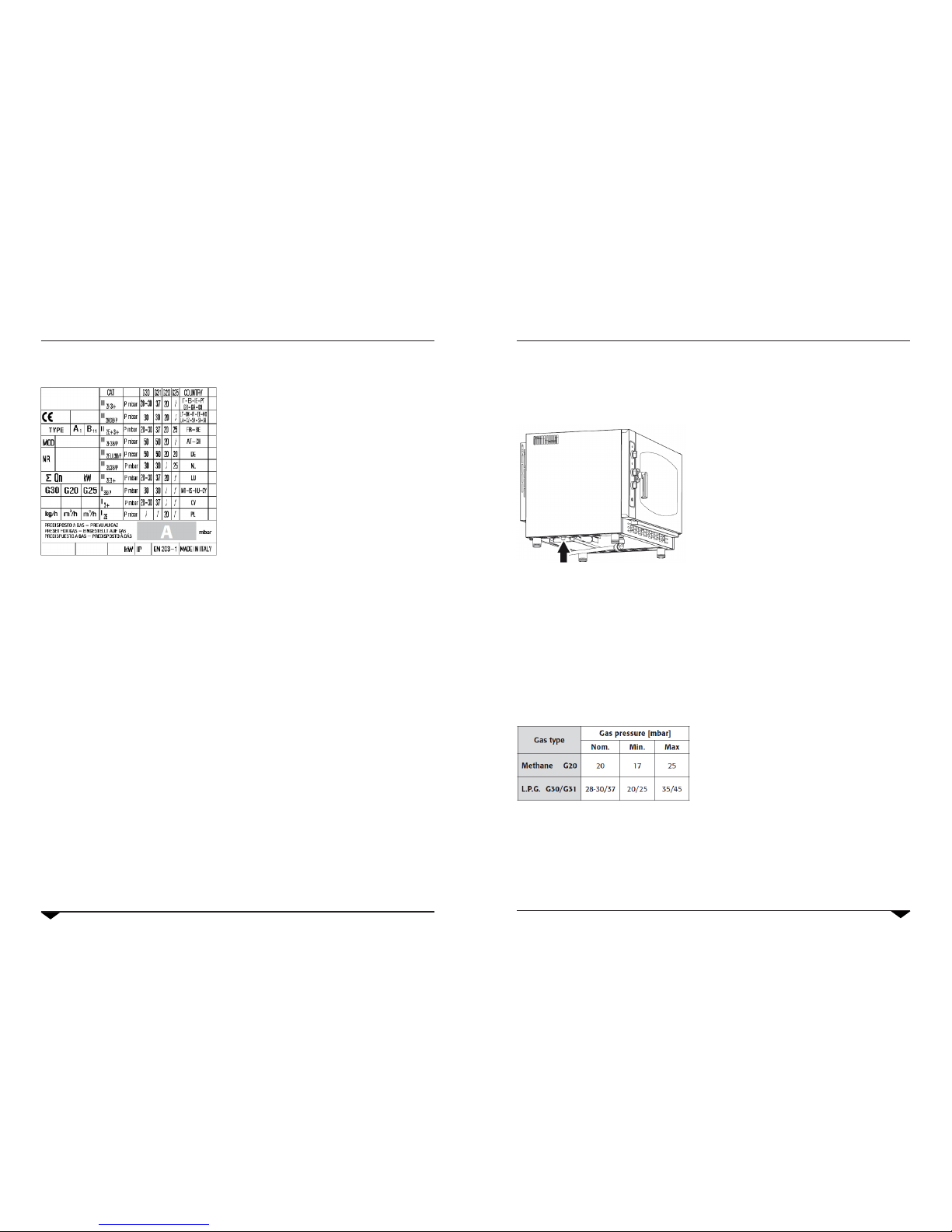
1.3
Checking gas pressure
6
1.4
Replacing nozzles (gas type change)
6
1.5 Electric connection 7
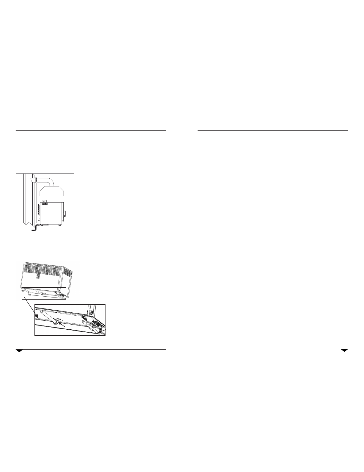
1.6
Fume discharge
8
1.7
Connection to the drain
8
1.8 Switching on oven and testing 9
2. Use instruction
2.1 Preliminary information 10
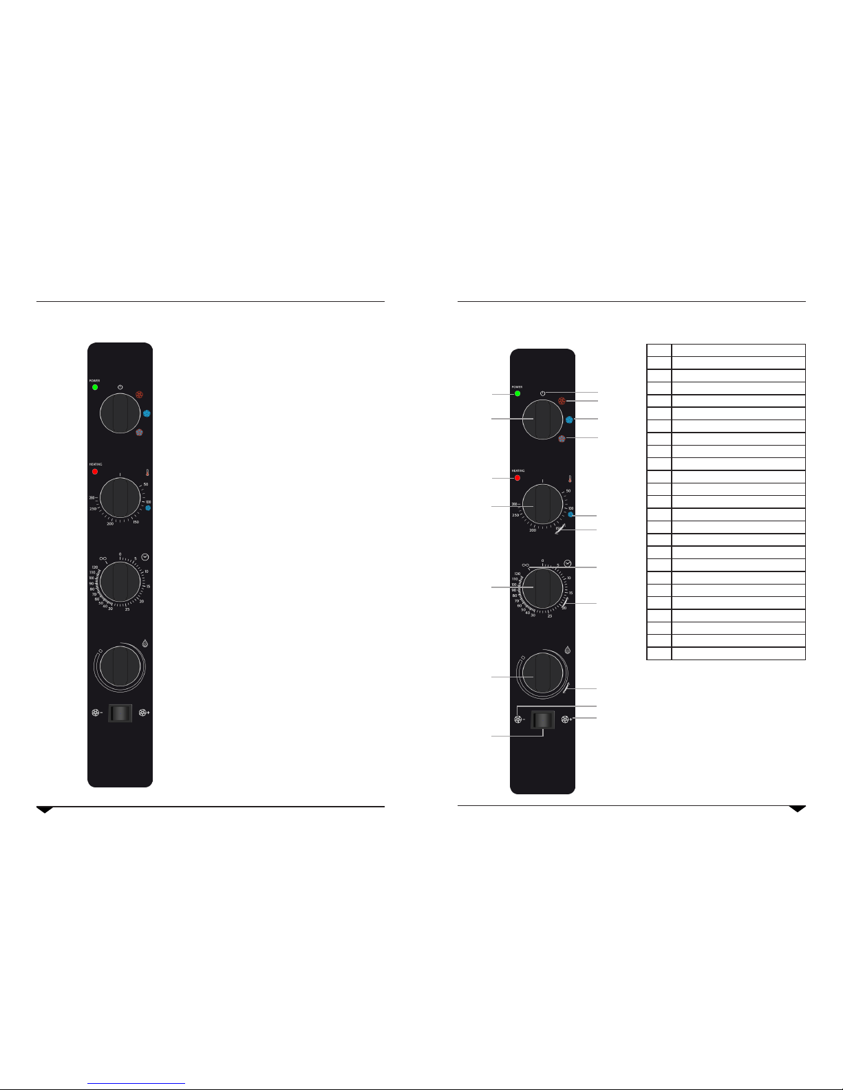
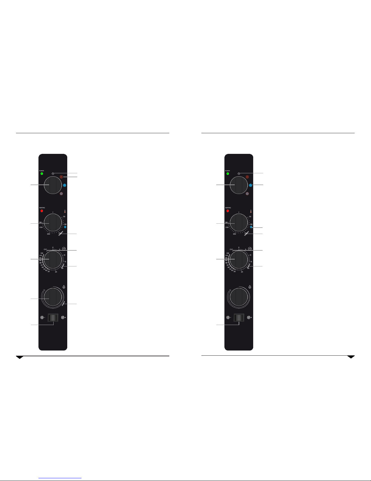
2.2 Control Panel 11
2.3 Convection cooking 12
2.4 Steaming 13
2.5 Convection/steam combi cooking 14
2.6 Humidity draining valve 15
2.7 Compartment lighting 15
2.8 Stop and oven swich off 15
2.9 Flame control (gas ovens only) 15
2.10 Other versions 16
4. What to do if...
4.1 Most common problems 18
4.2 Safety thermostat of the cooking
compartment
19
3. Maintenance
3.1 Cleaning 17
3.2 Cleaning of the glass 17
Dear Customer,
We thank you for having purchased our product.
This oven is part of a line of appliances specically designed for baking and patisserie, made of gas and electric
ovens with different capacities. The pleasant and modern design of these ovens provides ease of use, ergonomics
and cooking control.
The oven has a 12 month warranty against any manufacturing faults, starting from the date on the sales invoice.
The warranty covers the normal functioning of the oven and does not include the consumption materials (lights,
gaskets, etc.) and faults caused by incorrect installation, wear, maintenance, repair, decalcication & cleaning,
tampering and improper use.
The manufacturer reserves the right at any time to make changes or necessary amendments to the product.
• Carefully read this manual before installing and com-
missioning the oven. The text gives important indi-
cations regarding the safe installation, operating and
maintenance of the equipment.
• Keep this manual in a safe and easily accessible place
for further consultation by the operators.
• In case of transferring the oven, always attach the ma-
nual; if necessary, a new copy must be requested from
the authorised dealer or directly from the manufactu-
ring company.
• Once unpacked, ensure the oven is intact and does not
show signs of damage due to transport. A damaged
appliance must never be installed and commissioned; if
in doubt, immediately contact the after-sales technical
assistance or your own dealer.
• The appliance has been designed to cook food in closed
premises and must only be used for this purpose: any
other use must, therefore, be avoided as considered
improper and dangerous.
• The device is intended for professional use only by qua-
lied personnel
• The oven must only be used by staff adequately trained
for its use. To avoid the risk of accidents or damages to
the appliance, it is also fundamental that staff regularly
receive precise instructions regarding safety.
• The oven must not be used by persons with reduced
physical, sensorial or mental capacities or by persons
without experience and knowledge, unless supervised
or educated regarding the operating of the appliance by
a person responsible for their safety.
• Installation, extraordinary maintenance and repair
operations on the equipment must only be carried out
by professionally qualied staff.
• Children must be supervised to assure they do not
play with the appliance or use it.
• Caution! During working conditions, the external sur-
faces of the equipment may exceed 60 C.
• In case of fault or bad functioning, the equipment
must be deactivated; in case of repair, contact only
an after-sales technical assistance centre authorised
by the manufacturer and request original spare parts.
• Do not position other heat sources like, fryers or
hotplates, near the oven.
• Do not deposit or use ammable substances near the
equipment.
• In case of prolonged disuse of the appliance, both the
water and electric energy supply must be shut-off.
• Before commissioning the equipment, ensure to have
removed all packaging, being careful to dispose of it in
compliance with the Standard in force.
• Amendments to the oven wiring are not admitted.
• The non-compliance with the above warnings can je-
opardise the safety of the equipment and may injury
the operator of the oven.
The gas ovens comply with the essential requirements of 90/396/EEC Gas Directive and therefore have the EC
conformity certicate issued by an approved body. They satisfy the requirements of the following gas regulations:
• EN 203 + subsequent amendments;
• EN 437 + subsequent amendments.
Installation must be carried out in compliance with safety requirements contained in the following regulations:
• UNI CIG n° 7222-7723-8723 + subsequent amendments.
The appliance complies with the essential requirements of the Low Voltage Directives 2006/95/CEE. It satises the
requirements of the following electrical regulations:
• EN 60335-1 + subsequent amendments;
• EN 60335-2-42 + subsequent amendments;
• EN 60335-2-46 + subsequent amendments;
• EN 60335-2-36 + subsequent amendments;
• EN 55104 / EN 55014 + subsequent amendments;
• EN 61000 + subsequent amendments.
The appliance complies with the essential requirements of the Electromagnetic Compatibility Directive 2004/108/
CEE.
1. Installation
1.1 General and safety warnings
5. Data sheet
5.1 ME523 - ME5232 - MME523 19
5.2 ME5232X - ME5232K1 - ME5232K2 20
5.3 ME5 - ME52 - MME52 - ME52X 21
5.4 ME7 - ME72 - MME72 - ME72X 21
5.5 ME10 - ME102 - MME102 - ME102X 22
5.6 MG5 - MG52 - MMG52 23
5.7 MG7 - MG72 - MMG72 23
5.8 MG10 - MG102 - MMG102 24
5.9 MR3 - MR32 - MR31 - MR312 25
5.10 MR4 - MR42 25
5.11 ME423 - ME4232 26
6. Electrical drawings
Electrical drawings 27-42