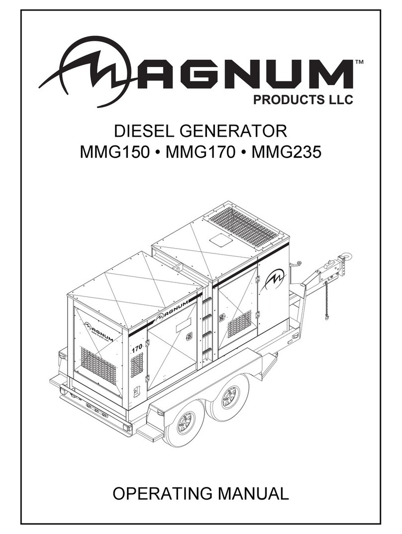
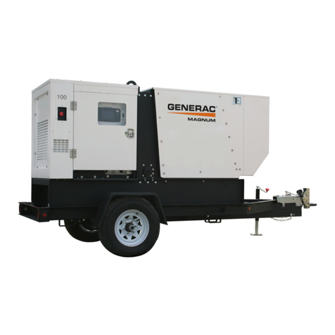
Magnum MLG 25 Application guide

25
www m-p-llc com
DIESELGENERATOR
MLG 25
OPERATION/PARTS MANUAL

2
This manual provides information and procedures to safely operate and maintain the generator.
Foryourownsafetyandprotectionfromphysicalinjury,carefullyread,understand,andobservethe
safetyinstructionsdescribedinthismanual. THEINFORMATIONCONTAINEDINTHISMANUAL
ISBASEDONMACHINESINPRODUCTIONATTHETIMEOFPUBLICATION. MAGNUMPROD-
UCTSLLCRESERVESTHERIGHTTOCHANGEANYPORTIONOFTHISINFORMATIONWITH-
OUTNOTICE.
An engine operators manual was supplied with the machine at the time of its shipment from the
factory. Themanual providesdetailedoperationandmaintenance proceduresfortheengine. Ad-
ditionalcopiesof thismanualare availablefromthe enginemanufacturer.
MAGNUM PRODUCTS LLC
215 POWER DRIVE
BERLIN, WI 54923
PHONE: 920-361-4442
FAX: 920-361-4416
TOLL FREE: 1-800-926-9768
www.m-p-llc.com
Engine Make:
Engine Serial #:
Engine Model #:
Generator Make:
Generator Model #:
Generator Serial #:
Unit Model #:
Unit Serial #:

3
TABLE OF CONTENTS
TABLE OF CONTENTS PAGE 3
SAFETY NOTES PAGE 4
UNITSERIALPLATE LOCATION PAGE 4
SAFETY NOTES PAGES 5 - 6
SPECIFICATIONS PAGE 7
EXTERIOR LOCATIONS PAGE 8
MAINCONTROLPANEL PAGE 9
ENGINE CONTROLLER FEATURES PAGES 10 - 11
GENERATORANDENGINE MONITORING PAGE 12
GENERATOR OUTPUT CONNECTION LUGS PAGE13
VOLTAGE SELECTOR SWITCH PAGE14
AUXILIARYOUTLETS PAGE 15
VOLTAGEREGULATOR PAGE 15
FINEVOLTAGEADJUSTMENT PAGE 15
EMERGENCY STOP SWITCH PAGE15
MAINCIRCUIT BREAKER PAGE 16
REMOTE STARTTERMINALBLOCK PAGES 16 - 17
GENERATORSTARTING PAGES 18 - 20
REMOTESTARTING PAGE 20
SHUTTINGDOWN PAGE20
EZ-1CONTROLLER INFORMATION DISPLAYS PAGE 20
CONTROLLERALARM LIST WITH DESCRIPTIONS PAGES 21 - 22
TROUBLESHOOTINGAUTO SHUTDOWN CONDITIONS PAGES 22 - 23
TOWING THE TRAILER PAGE 23
TRAILERWHEEL BEARINGS PAGE 23
ENGINEANDGENERATORMAINTENANCE PAGE 24
RELOADINGTHE TIME TO SERVICE REMINDER PAGE 24
ADJUSTINGDISPLAYBACKLIGHTING PAGE24
DAILYMAINTENANCECHECKS PAGE25
DERATING FORALTITUDE PAGE25
FRAMEASSEMBLY PAGES 26 - 27
ENCLOSURE ASSEMBLY PAGES 28 - 29
AUXILIARYOUTLETPANELASSEMBLY PAGES 30 - 31
AUXILIARYOUTLETPANELOPTIONS PAGES 32 - 33
ENGINECOOLINGASSEMBLY PAGES 34 - 35
ENGINEASSEMBLY PAGES 36 - 37
CONTROLPANELASSEMBLY - OLD STYLE PAGES 38 - 39
CONTROLPANELASSEMBLY - NEW STYLE PAGES 40 - 41
CONTROLBOXASSEMBLY - OLD STYLE PAGES 42 - 43
CONTROLBOXASSEMBLY - NEW STYLE PAGES 44 - 45
LUG DOORASSEMBLY PAGE 46
GENERATORASSEMBLY PAGE 47
WIRINGDIAGRAMS PAGES 48 - 51

4
UNIT SERIAL PLATE LOCATION
SAFETY NOTES
This manual contains NOTES, CAUTIONS and WARNINGS which must be followed to prevent the
possibilityofimproperservice,damagetotheequipment,orpersonalinjury. Thefollowingformattingoptions
will apply when calling the readers attention to the NOTES, CAUTIONS and WARNINGS.
Notes: Notes contain additional information important to a procedure. The notes called out in this manual
will be included in theregular text body but theword “Note” will bein BOLD text and the note willbe written
in italics to make them more visible. For example: Note: Check the engine oil level before starting.
CAUTION: Cautions provide information important to prevent errors which could damage the equipment.
The cautions called out in this manual will be in BOLD text, in a separate paragraph or sentence from the
regular text body. For example:
CAUTION! Always switch all circuit breakers to “OFF” to prevent the starting of the generator
under load.
WARNINGS:Warningsdescribeconditionsorpracticeswhichcouldleadtoseriouspersonalinjuryordeath
to the operator or others around the equipment. Warnings called out in this manual will be in a separate
paragraph, centered and surrounded by a black border, with warning in BOLD text. For example:
25
wwwm-p-llc com
MANUFACTURED BY/FABRIQUE PAR:
GVWR/PNBV:
DATE OF MFG:
COLD INFL. PRESS./PRESS.
GAWR/PNBE TIRE/PNEU RIM/JANTE KPA(PSI/LPC)
THIS VIEHICLE CONFORS TO ALL APPLICABLE STANDARDS PRESCRIBED UNDER THE CANADIAN MOTORVIEHICLE SAFETY REGULATIONS
IN ECCEFT ON THE DATE OF MANUFACTURE. / CE VEHICULE EST CONFORME A TOUTES LES NORMES QUI LUI SONT APPLICABLES EN
VERTU DU REGLEMENT SUR LA VEHICULES DES AUTOMOBILES DU CANADAEN VIGUEUR A LA DATE SA FABRICATION.
THIS VIEHICLE CONFORMS TO ALL APPLICABLE U.S. FEDERAL MOTOR VEHICLE SAFETY STANDARDS (FMVSS) IN EFFECT ON THE DATE OF
MANUFACTURE SHOWN ABOVE.
V.I.N./N.I.V.: TYPE/TYPE DE VEHICULE:
kg lbs
rpm hz amb. temp.
Serial Number
V
A
MADE IN USA
REV
Model
RATING: CONT. STAND BY
3 Phase 1 Phase
kVA
Magnum Products LLC
Berlin, WI 54923 USA
(800) 926-9768
R
LR 114630-1
WARNING!
Only a qualified electrician may service or make connections
to the generator. Lethal voltage is present at the connection
lugs when the generator is running!

5
OPERATING SAFETY
Before using the generator be sure you read and understand all instructions! Equipment operated
improperly or by untrained personnel can be dangerous! Read the operating instructions and familiarize
yourself with the location and proper use of all instruments and controls. Inexperienced operators should
receiveinstruction from someone familiar withthe equipment before being allowedto operate or set upthe
generator.
The area immediately surrounding the generator should be clean, neat, and free of debris.
Position and operate generator tower on a firm, level surface.
NEVER start a unit in need of repair.
NEVER modify the generator or use it in a manner other than what it was designed for.
ALWAYSkeepthegeneratordoorsclosedwhentheengineisrunning. Donotstartthegeneratorifany
panels or guards are loose or missing.
ALWAYS connect the generator to a good earthen ground.
Move the generator main circuit breaker to the “OFF” position when servicing or troubleshooting the unit.
The output voltage of the generator can cause afatalelectricshock. Avoidcontactwithanyalternating
current wiring when the engine is running. Make sure any extension cords or equipment connected to
the convenience outlets are in good working condition.
NEVER remove control box cover when the engine is running. Exposed live electrical terminals can
cause a fatal electrical shock.
Check your electrical requirements before installing or starting the generator.
Use a ground fault circuit interrupter (GFCI) in damp or highly conductive areas and construction sites
to prevent electrical shock.
ENGINE SAFETY
Internal combustion engines present special hazards during operation and fueling! Failure to follow the
safety guidelines described below could result in severe injury or death. Also read and follow all safety
warnings described in the Engine Operator's Manual. A copy of this manual was supplied with unit when
it was shipped from the factory.
DO NOT run engine indoors or in an area with poor ventilation unless exhaust hoses are used.
DO NOT fill fuel tank near an open flame, while smoking, or while engine is running.
DO NOT fill tank in an enclosed area with poor ventilation.
DO NOT touch or lean against hot exhaust pipes or engine cylinder.
DO NOT operate with the fuel tank cap loose or missing.
DO NOT remove engine coolant cap while engine is hot.
DO NOT clean air filter with gasoline or other types of low flash point solvents.
Keep area around exhaust pipes and air ducts free of debris to reduce the chance of an accidental fire.
Shut the engine down if any of the following conditions exist during operation:
A. Noticeable change in engine speed.
B. Loss of electrical output.
C. Equipment connected to the generator overheats.
D. Sparking occurs.
E. Engine misfires or there is excessive engine/generator vibration.

TOWINGSAFETY
Towing a trailer requires care! Both the trailer and vehicle must be in good condition and securely fastened to
each other to reduce the possibility of an accident. Also, some states require that large trailers be registered
andlicensed. ContactyourlocalDepartmentofTransportationofficetocheckonlicenserequirementsforyour
particular unit.
Checkthatthehitchandcouplingonthetowingvehicleareratedequalto,orgreaterthan,thetrailer's"gross
vehicle weight rating" (GVWR). Check tires on trailer for tread wear, inflation, and condition.
Inspect the hitch and coupling for wear or damage. DO NOT tow trailer using defective parts!
Make sure the trailer hitch and the coupling are compatible. Make sure the coupling is securely fastened
to the vehicle.
Connect safety chains in a crossing pattern under the tongue and attach the brake away cable TO THE
REAR BUMPER OF THE TOWING VEHICLE.
Make sure directional and brake lights on the trailer are connected and working properly.
Check that lug nuts holding wheels are tight and that none are missing.
Maximum recommended speed for highway towing is 45 m.p.h.. Recommended off-road towing speed
is not to exceed 10 m.p.h. or less depending on terrain.
When towing, maintain extra space between vehicles and avoid soft shoulders, curbs and sudden lane
changes. If you have not pulled a trailer before, practice turning, stopping, and backing up in an area away
from heavy traffic.
A film of grease on the coupler will extend coupler life and eliminate squeaking. Wipe the coupler clean and
apply fresh grease each time the trailer is towed.
REPORTING TRAILER SAFETY DEFECTS
If you believe your trailer has a defect which could cause a crash or could cause injury or death, you should
immediately inform the National Highway Traffic SafetyAdministration (NHTSA) in addition to notifying
Magnum Products LLC. If NHTSA receives similar complaints, it may open an investigation; and if it finds
that a safety defect exists in a group of vehicles it may order a recall and remedy campaign. However,
NHTSAcannot become involved in individual problem between you, your dealer, or Magnum Products LLC.
To contact NHTSA, you may either call theAuto Safety Hotline toll-free at 1-888-327-4236 or by fax at:
(202)-366-7882. Additional contact information can be found at: www.nhtsa.dot.gov.
SERVICE SAFETY
This unit uses high voltage circuits capable of causing serious injury or death. Only a qualified electrician
should troubleshoot or repair electrical problems occurring in this equipment.
Before servicing the generator, make sure engine start switch is turned to OFF, circuit breakers are open
(off) and the negative terminal on the battery is disconnected. Open main circuit breaker before
disconnecting battery cables. NEVER perform even routine service (oil/filter changes, cleaning, etc.)
unless all electrical components are shut down.
NEVERallowwatertoaccumulate aroundthebaseof the generator. Ifwaterispresent,DO NOTservice!
NEVERserviceelectricalcomponentsifclothingorskiniswet. Iftheunitisstoredoutside,checktheengine
and generator for any moisture and dry the unit before use.
NEVER wash the unit with a power washer or high pressure hose.
Keep hands, feet, and loose clothing away from moving parts on generator and engine.
Replace all guards and safety devices immediately after servicing.
Replace all missing and hard-to-read labels. Labels provide important operating instructions and warn of
dangers and hazards.
Makesure slings, chains,hooks, ramps, jacks, andother types oflifting devices are attachedsecurely and
have enough weight-bearing capacity to lift or hold the equipment safely. Always remain aware of the
position of other people around you when lifting the equipment.
6
SPECIFICATIONS
Engine manufacturer ISUZU
Engine model 4LE1-PV05
Enginetype Diesel, 4-cyl, liquid cooled 4-stroke
Engine horsepower (standby) 34.5 hp (25.7 Kw) @1800 RPM
Engine horsepower (primed) 31.5 hp (23.5 Kw) @1800 RPM
Fuel tank capacity 56 gal. (215.8 L)
Fuel consumption 2.1 gph (7.90 Lph)
Generator manufacturer Marathon Electric
Generator model 282NSL1505
Generator output 3O Standby Kw/Kva 20/25
Generator output 1O Standby Kw/Kva 16/16
Generator output 3O Prime Kw/Kva 18/23
Generator output 1O Prime Kw/Kva 15/15
Generatorfrequency 60 Hz
Generator output voltage 3O 208/220/440/480V
Generator output voltage 1O 120/138/208/220/240/277V
Generator outputAmperes 3O (480/208) 30/69
Generator outputAmperes 1O (240) 67
Generator power factor 0.8
Generatorinsulation Class “H1”
Width 67 in. (170.2 cm)
Weight (no fuel) 1570 lbs (710 kg)
Weight with fuel (approx.) 2000 lbs. (910 kg)
Height 56 in. (142.2 cm)
7

25
wwwm-p-llc com
5
3
7
2
1
4
6
1. FUEL FILLER LOCATION (under door): Use clean DIESEL FUEL ONLY.
2. RADIATORACCESS PANEL: Remove this panel for engine coolant service.
3. CONTROL PANEL LOCATION (under door): Engine/generator controls and all circuit breakers.
4. EMERGENCY STOP SWITCH: For emergency shutdown; stops engine and trips main circuit breaker.
5. EQUIPMENT OUTLETS: Circuit breaker protected outlets; 20, 30 and/or 50 amp ratings.
6. GROUND STUDS (2): For grounding generator and equipment connected to the equipment outlets.
7. TONGUE JACK: Used to level generator before starting.
8
EXTERIOR LOCATIONS

2
MAIN CONTROL PANEL
1. MAIN CIRCUIT BREAKER (90A): This breaker will disconnect power to the connection lugs.
2. ENGINE CONTROLLER PANEL: See pages 10 - 11 for additional information.
3. AUXILIARY OUTLET MAIN CIRCUIT BREAKER (100A): This breaker disconnects power to the
auxiliaryequipment outlets.
4. PHASE SELECTOR SWITCH: This switch will change the generator output between three phase and
single phase power. See the “VOLTAGE SELECTOR SWITCH” section for more information.
5. REMOTE START TERMINAL BLOCK: Allows for remote starting of the generator.
6. LUG DOOR SAFETY SWITCHES: These switches will shut the generator down if the lug door is
opened when the generator is running.
7. GENERATOR GROUND CONNECTION LUG: This lug is for connecting a good earthen ground per
any local, state or National Electric Code (NEC) guidelines before starting the generator.
8. GENERATOR OUTPUT CONNECTION LUGS: These allow appropriate loads to be wired directly to
thegenerator. 9
64
1
5
3
7
8
6

10
1. LCD DISPLAY
This display shows the controller status in, MANUAL andAUTO (remote start) modes.
Should a shut down fault occur, the LCD display will show the condition causing the fault. At the
same time, the engine will shut down and lock out.
The LCD display will also show any possible Engine Sender Failures and Time To Service
information. These conditions will not shut down the engine; they are used to alert the operator.
2. OPERATION KEYS
MANUAL Press to switch fromAUTO to MANUAL mode.
AUTO Press to switch from MANUAL toAUTO mode for remote starting of
generator.
ENGINESTART Press to start engine.
ALARMCANCEL Press to cancel alarms (visual or audio if equipped).
FAULT RESET Press to clearALARM LIST fault codes.
ENGINESTOP Press to stop engine.
3. CONTROL POWER SWITCH
This main power switch turns the controller on and off.
4. VOLTAGE ADJUSTMENT RHEOSTAT
This knob allows the end user to fine adjust the output voltage from the generator.
5. OPERATION STATUS LED’S
ALARM/ FAULT Indicates active or inactive alarms.
READY/MANUAL Indicates controller is in MANUAL mode, ready to start.
RUNNING Indicatesrunning engine.
WARNING Indicates active or inactive warnings.
READY/AUTO Indicates controller is in AUTO mode, ready for remote start signal.
SUPPLYINGLOAD Indicates the genset is running, giving proper voltage and frequency and
is supplying load.
ENGINE CONTROLLER FEATURES
ENGINE
ENGINE
START
START
ENGINE
ENGINE
STOP
STOP
MANUAL AUTO
ALARM
CANCEL
FAULT
RESET
ALARM/FAULT
READY/MANUAL READY/AUTO
WARNING
RUNNING SUPPLYING LOAD
OPERATION
PAGE
SELECT
ENTER
DIAGNOSTICS
STATUS
CONTROL
CONTROL
ON
ON
CONTROL
CONTROL
OFF
OFF
MAN AUT
Ready
PF 0.00
RPM 0
0 kW 0
6
3
5
1
2
4

11
6. DIAGNOSTICS
UP
DOWN Switch between:
POWER SCREEN DISPLAY (DISPLAYS FROM MANUALTOAUTO MODE)
ALARMSCREEN DISPLAY
HOUR SCREEN DISPLAY
POWER DETAIL SCREEN DISPLAY
Note:Automatically returns to flipping between the ENGINE / GENERATOR DISPLAY SCREENS
after 60 seconds.
PAGE SELECT Provides access to programming and resets.
ENTER Allows access to the next level.

ENGINE MONITORING
Engine information is shown on the LCD display in a repeating manner while the unit is in MANUAL or
AUTO mode. Engine information will show the oil pressure, water temperature, fuel level and battery
voltage.
8. OIL - Displays engine oil pressure. The display registers oil pressure between 0-100 psi. Normal
operating pressure is between 35-80 psi.
9. TEMPERATURE - Displays the temperature of the engine’s coolant. If the coolant temperature
exceedsthe Max WaterTemp the enginewill automatically shut down. Zero “0”will be displayed until a
minimum of 100° F is reached.
10. FUEL - Displays the relative fuel level in the fuel tank in percent (50% = 1/2 tank, 75% - 3/4 tank, etc.).
If the fuel level drops below a programmed Fuel Shutdown Percent the engine will automatically shut
down.
11. BATTERY - Displays the engine battery voltage. Anormal reading is 13-14V on 12 volt systems and
24-26V on 24 volt systems.
GENERATOR MONITORING
Generator information is shown on the LCD display in a repeating manner while the unit is running in
MANUAL orAUTO mode. Generator information will show the voltage, amperage and frequency of each
phase.
Additional information can be viewed when the unit is MANUAL or AUTO modes. Pressing “PAGE SE-
LECT” then “UP” or “DOWN” on the key pad will display, Alarm Screen, Hour Screen, and Power Detail
Screen displays.
NOTE: Whenloading the generator it is importantto observe the amperage to determinetheload balance
on each line of the generator. Minor load unbalances, usually 5% or less, will not cause any particular
problems. Every effort should be made to distribute the load equally between all lines.
1. PHASE - Indicates generator configuration, 3 phase or single phase.
2. HERTZ - Displays output frequency.
3. NOMINAL VOLTS - Displays generator nominal voltage in current phase switch selection.
4. NOMINAL AMPS - Displays maximum amps in current phase switch selection.
5. GENERATOR OUTPUT VOLTAGE - Line to Line display.
6. AMPS - Displays theAC output amperage produced by the generator.
7. GENERATOR OUTPUT VOLTAGE - Line to Neutral display.
Gen freq 60.0Hz
Gen freq 60.0Hz
NomVolt (3PY)
NomVolt (3PY)
208V
208V
NomAmps 300A
NomAmps 300A
L1N 120V L12 208V
L1N 120V L12 208V
L2N 120V L23 208V
L2N 120V L23 208V
L3N 120V L31 208V
L3N 120V L31 208V
G-Curr 0 0 0 A
G-Curr 0 0 0 A
1
2
3
4
5
6
7
Oil Press 49 psi
Oil Press 49 psi
Water Temp 183°F
Water Temp 183°F
Fuel Level 83%
Fuel Level 83%
Batt Volts 13.4V
Batt Volts 13.4V
8
9
10
11
12

GENERATOR OUTPUT CONNECTION LUGS
The generator is equipped with connection lugs behind a door below the controller face. The lugs provide
connection points for attachment of external loads to the generator. A large decal on the inside of the
connection lug door details the proper connections for selected voltages.
Connections to the lugs should be made by running the power cables through the circular plastic bushing
onthe lower right side ofthe control box. DO NOT makeany connections directly to the lugwithout routing
thecables through this bushing. Theconnection lug door isequipped with a safetyinterlock switch that will
automatically trip the main circuit breaker and disable the voltage regulator when the lug door is opened.
Use a 5/16” hex-wrench to tighten the cable connections.
A ground connection is located next to the connection lugs. The unit MUST HAVE this ground lug con-
nected to a good earthen ground for proper operating safety. The ground connection SHOULD BE IN
COMPLIANCE WITH THE NATIONAL ELECTRIC CODE (NEC)AS WELLAS ANY STATE OR LOCAL
GUIDELINES OR CODES.
WARNING!
It is HIGHLY RECOMMENDED that only a trained and licensed electri-
cian perform any wiring and related connections to the generator. Instal-
lation should be in compliance with the NATIONAL ELECTRIC CODE
(NEC) as well as any local or state guidelines as required by law. Failure
to follow proper installation requirements may result in equipment or
property damage, personal injury or death.
WARNING!
Before any connections are made to the generator, make sure that the
main circuit breaker and the control power switch are in the OFF “O”
position. Potentially lethal voltages may be present at the generator
connection lugs.
WARNING!
Improper or incorrect connections to a buildings electrical system can
cause potentially lethal voltages to backfeed onto utility lines. This
may result in injury or electrocution to utility workers nearby. Make
sure the generator is suppling power to an isolated object or building
that is not connected to any utility lines.
13

14
VOLTAGE SELECTOR SWITCH
The voltage selector switch is located on a panel attached to the generator behind the door located next to
the fuel tank filler. The selector switch is a three position switch that mechanically changes the connec-
tions between the generator output leads and the connection lugs on the main control panel. Voltage
ranges are selected by rotating the handle on the switch to the desired voltage.
The voltage switch is equipped with a locking mechanism. Once the proper voltage has been selected,
push the red latch on the inside of the phase switch handle up and insert a padlock through the handle. By
locking the handle in place you will prevent unauthorized personnel from changing the switch settings.
NOTE: When the voltage selector switch is in position for 480/277V 3O, voltage at the two GFCI duplex
convenience outlets is 139 Volts and the voltage at the three twist-lock outlets is 240/139 Volts. When the
voltage selector switch is in position for 208/120V 3O, voltage at the three twist-lock outlets and the two
GFCI outlets is 208/120 volts.
T1
L1
T4
T7
T10
N
T2
L2
T8
T5
T9
T6
T3
L3
T11
T12
L-N
L-L
T4
T7
T10
T1
L1
L2
T8
T2
T9
T3
T6 T11
L3
T5
T12 N
L-N
L-L
T10 T7
T6 T8
T12 T2 T11
T3
T4 T1
T5
T9
L3
N
L1
120V120V
240V
WARNING!
NEVER CHANGE THE VOLTAGE SELECTOR SWITCH WHILE THE ENGINE
IS RUNNING! THIS WILL CAUSE SEVERE ARCING AND DAMAGE TO THE
SWITCH AND GENERATOR WINDINGS.
480/277V
3-PHASE
208/120V
3-PHASE
240/120V
1-PHASE

AUXILIARY OUTLETS
The control panel is equipped with six outlets for
running accessories or tools from the generator.
Power is supplied to the outlets any time the en-
gine is running and the main circuit breaker and
theauxiliaryoutletmaincircuitbreakerareswitched
on“I”.
Should the main breaker trip, or the auxiliary out-
let main circuit breaker trip, remove some of the
load to the outlets before turning them back on.
Note: To ensure proper grounding, anytime the
generator is providing power to any equipment or
load panels that do not have a grounded plug a
ground wire must be added between the equipment and the grounding stud on the outlet panel per any
local, state or NEC codes and guidelines.
VOLTAGE REGULATION
Systemstability is the ability ofthe generator to respond to loadtransients. Decreasing stability makes the
generator less sluggish and faster to respond to load transients. If the stability of the regulator is de-
creased too much, the generator will tend to hunt under steady state conditions. To adjust the regulation,
see the included manual for the voltage regulator. The regulator is located behind the control panel on the
back of the generator box.
FINE VOLTAGE ADJUSTMENT
The output voltage can be fine adjusted after the generator is running by using the fine voltage adjustment
knob. Theswitch is located directly below the control power switchnext to the control panel. This rheostat
will provide an increase (“+”) or a decrease (”-”) in the output voltage. To adjust the voltage, check the
outputvoltageon theLCD display. Turn theknob in thedesired direction untilthe required voltageis shown
on the LCD display.
EMERGENCY STOP SWITCH
The generator is equipped with one emergency stop switch,
located on the side panel next to the auxiliary outlet panel.
Theswitch is clearly labeled with“EMERGENCY STOP”and
is red in color. The switch can be accessed and activated
with all doors closed and locked.
Activate the emergency stop switch by pushing the red but-
tonin until itlocks down. This will tripthe main circuit breaker
whichwill open thecontact disconnecting theload to thecon-
nectionlugs. This willalso openthe fuelpump solenoid,shut-
ting down the engine and the Emergency Stop fault will be
displayedon the LCD. The switch will remain closed until it is
pulledout.
CAUTION! Use the EMERGENCY STOP only when the generator must be shut down immediately.
For any other shut down, follow the detailed shut down procedure.
15
AUXILIARYOUTLET
GROUNDINGSTUD

MAIN CIRCUIT BREAKER
The main circuit breaker is located on the main control panel. When the breaker is in the off “O” position,
power is interrupted between the customer connection lugs and the generator. Once the connections
have been made to the connection lugs and the generator has been started and allowed to reach normal
operating temperature, the breaker may be switched to the on “I” position.
The main circuit breaker will be tripped, disconnecting power to the connection lugs, if any of the following
items occur while the unit is running:
1. Overload of the generator circuits to the connection lugs.
2. The door covering the customer connection lugs is opened.
3. If the emergency stop switch is activated.
Make sure that any problems that caused the main circuit breaker to trip are corrected before returning the
switch to the on “I” position.
REMOTE START TERMINAL BLOCK
The remote start terminal block is located under the lug box door just below the voltage selector switch. It
providesa connection for installationof a remote start switchwhich will allow the generatorto be started by
a remote dry-contact closure switch.
Before pressing the “AUTO” button, verify that the contacts on any remote switch linked to the generator
are OPEN. If the contacts on a remote switch are closed, the generator will crank and start whenAUTO is
selected on the controller. Attach the switch leads to the two unused terminals on the generators remote
start block. For additional information on starting the generator, see GENERATOR START UP section of
this manual.
When the generator is used as a standby power supply, it must be equipped with a transfer switch which
isolates it from the utility’s distribution system. A transfer switch is designed to transfer electrical
loads from the normal power source (utility) to the emergency power source (generator) when normal
voltage falls below a prescribed level. The transfer switch automatically returns the load back to the
normal source when power is restored back to operating levels.
WARNING!
Failure to isolate the generator from the normal power utility can cause
potentially lethal voltage to backfeed into the utility lines. This may result in
injury or electrocution of utility workers nearby. Make sure that the generator
is isolated by a transfer switch from any local utility lines. This also applies if
the generator is being used as a back up to some other type of power supply.
16
WARNING!
THE MAIN CIRCUIT BREAKER INTERRUPTS POWER TO THE CUSTOMER
CONNECTION LUGS ONLY. THE CUSTOMER CONVENIENCE OUTLETS HAVE
POWER EVEN IF THE MAIN CIRCUIT BREAKER IS IN THE OFF “O” POSITION.
The auxiliary outlet main circuit breaker, located next to the main circuit breaker,
will disconnect all power to the auxiliary outlet panel.

Installation of a transfer switch or other type of remote starting device is the responsibility of the generator
user. Installation of such devices must be performed by following all directions supplied by the manufac-
turer of the switch. If attaching generator to a power supply normally serviced by a utility company, notify
the utility company and check local and state regulations. Familiarize yourself with all instructions and
warning labels supplied with the switch.
17
INCOMING
UTILITY
POWER
WHITE = INCOMING UTILITY POWER
GRAY = NORMAL UTILITY POWER CIRCUIT
BLACK = EMERGENCY GENERATOR POWER CIRCUIT
UTILITY
METER
TRANSFER
SWITCH
MAIN DISTRIBUTION
PANEL
(UTILITY POWER)
EMERGENCY
DISTRIBUTION PANEL
(GENERATOR POWER)
POWER FROM
GENERATOR
WARNING!
It is strongly recommended that ONLY a licensed electrician perform any
wiring and any related connections to the generator. Installation should be in
compliance of the National Electric Code as well as any state or local codes or
regulations. Failure to follow these procedures could result in property
damage, personal injury or death. Before any connections are attempted,
make sure the main circuit breaker and the engine start switch are in the
OFF “O” position.
WARNING!
When using the generator as a stand by or substitute power supply, make sure
the output voltage and phase rotation of the generator match those of the
local power utility. Improper voltage or phase rotation may cause equipment
damage or malfunction.

18
OPERATION STATUS
ALARM/FAULT
READY/MANUAL
RUNNING
WARNING
READY/AUTO
SUPPLYING LOAD
65h
65h
ComAp 2005
ComAp 2005
MMG
MMG
IL-MRS17-JD-1.1.1
IL-MRS17-JD-1.1.1
Serial: 11353559
Serial: 11353559
SW vers: 1.1, 1.1
SW vers: 1.1, 1.1
Appl: MRS17
Appl: MRS17
Branch: JD
Branch: JD
GENERATOR START UP
Before starting the generator, carefully read the pre-start check list. Make sure that all of the items are
checked before trying to start the generator. This check list applies for both manual and remote starting
of the generator.
PRE-START CHECK LIST
1. Make sure the control power switch is in the OFF “O” position.
2. Make sure that the circuit breakers (main and convenience) are switched OFF “O”.
3. Check that the generator is properly grounded to a good earthen ground per local and
NEC regulations.
4. Check all electrical connections at the connection lugs. Are they wired correctly?
5. Are the connection lugs tight?
6. Check the voltage selector switch and make sure that it is set to the desired voltage.
7. Is the voltage selector switch locked?
8. Is the generator sitting level?
9. Check for any water inside the unit, on or near the generator. Dry the unit before starting.
10. Check engine oil level, engine coolant level and engine battery connections.
11. Check engine fan belt tension and condition.
12. Check engine fan belt guard.
13. Check engine exhaust system for loose or rusted components.
14. Check radiator and surrounding shroud for debris.
15. Are any of the generator covers loose or missing?
MANUAL STARTING OF THE GENERATOR
1. Move the control power switch to the “CONTROL ON” position.
2. The LCD screen will quickly display system information, all LEDS will flash.
OPERATION STATUS
ALARM/FAULT
READY/MANUAL
RUNNING
WARNING
READY/AUTO
SUPPLYING LOAD
MAN
MAN
AUT
AUT
Ready
Ready
PF 0.00
PF 0.00
RPM 0
RPM 0
0 kW 0
0 kW 0
3. The LCD Screen will indicate MANUALmode and Ready. Ready/Manual LED will be lit.
4. Press the green ENGINE START key.
NOTE: Unit must be in MAN Mode with READY/MANUAL LED lit.

19
OPERATION STATUS
ALARM/FAULT
READY/MANUAL
RUNNING
WARNING
READY/AUTO
SUPPLYING LOAD
MAN
MAN
AUT L
AUT L
Starting
Starting
PF 1.00L
PF 1.00L
RPM 250
RPM 250
0 kW 0
0 kW 0
OPERATION STATUS
ALARM/FAULT
READY/MANUAL
RUNNING
WARNING
READY/AUTO
SUPPLYING LOAD
MAN
MAN
AUT L
AUT L
Prestart
Prestart
PF 0.00
PF 0.00
RPM 0
RPM 0
Prestart
Prestart
0 kW 5
0 kW 5
9. If the engine does not start after the first cranking attempt the engine will wait for 15 seconds to allow
the starter to cool and the LCD will show “Pause”. The engine will make two more attempts to start for
a total of three crank cycles.
10. Should the engine not start and run the LCD display will show “SD StartFail”. The starting sequence
may be repeated after the starter has had a minimum of two minutes to cool. The FAULT RESET
button needs to be pressed to clear the controller. The unit will start by pressing the ENGINE START
button.
Note: the engine controller may skip the pre-heat acquisition and engine pre-heat steps.
11. Once the engine starts it will slowly begin speeding up to a constant 1800 rpm. On units with isochro-
nousengine governing, the enginemay hunt or changespeeds until operating temperatureis reached.
After a few minutes of operation the engine will be warmed up and the LCD display will show engine
and generator operating parameters. Temperature will be shown as “0” until the engine temperature is
approximately 100 degrees Fahrenheit.
Oil Press 49 psi
Oil Press 49 psi
Water Temp 183°F
Water Temp 183°F
Fuel Level 83%
Fuel Level 83%
Batt Volts 13.4V
Batt Volts 13.4V
Gen freq 60.0Hz
Gen freq 60.0Hz
NomVolt (3PY)
NomVolt (3PY)
208V
208V
NomAmps 300A
NomAmps 300A
L1N 120V L12 208V
L1N 120V L12 208V
L2N 120V L23 208V
L2N 120V L23 208V
L3N 120V L31 208V
L3N 120V L31 208V
G-Curr 0 0 0 A
G-Curr 0 0 0 A
8. The LCD will switch from the POWER SCREEN DISPLAY to:
OPERATION STATUS
ALARM/FAULT
READY/MANUAL
RUNNING
WARNING
READY/AUTO
SUPPLYING LOAD
MAN
MAN
AUT L
AUT L
Running
Running
PF 1.00L
PF 1.00L
RPM 1800
RPM 1800
V Detect
V Detect
4 kW 15
4 kW 15
7. The Running screen will display.
NOTE: It may take a few seconds for the engine to run smoothly and reach its governed operating speed.
6. The Starting screen will display. The engine will crank and start running.
5. The Prestart screen will display (if equipped).

20
Once the generator is at normal operating temperature, check the generator for excessive noise, vibration
and coolant, oil or fuel leaks before applying any loads.
12. Check that theAC output voltage is correct. The output voltage can be fine adjusted by using the fine
voltage adjustment switch, described on page 16.
13. Check that the frequency (Hz) is correct. With no loads connected to the generator, the frequency
should read approximately 60-62 Hz, depending on the type of engine governing used.
14. If all wiring connections have been done correctly, switch the main circuit breaker to the on “I” position
andthen add any loadsattached to the convenienceoutlets by switching the respectivecircuit breaker
to the ON “I” position. You will notice a slight change in engine noise.
AUTO (REMOTE) STARTING OF THE GENERATOR
The AUTO button is used when the generator is started from a location other than the control panel by
using a remote start switch or transfer switch. AUTO (remote start) is the normal setting when the genera-
tor is being used as a standby power supply. Before putting the generator in the AUTO (remote start)
mode, review the PRE-START CHECK LIST and MANUAL STARTING OF THE GENERATOR sections
beginning on page 18. Also follow all safety warnings and information on isolating the generator with a
transfer switch if the unit is to be used as a standby power supply on pages 16 and 17. Then continue with
the steps described below:
1. Perform a manual start of the generator at least once to verify that the engine is operating correctly.
2. Ifacheck of the remote startcircuit is desired, pressthe“AUTO” button. The LCD displayshould high-
light “AUT” in the upper left corner. Attach a jumper wire (minimum 16 gauge) equipped with two
alligator clips across the two unused terminals on the remote start terminal block. This applies a
ground to the EZ-1 to close the starting circuit. The engine should crank, start and run.
3. Remove the jumper wire from the remote start terminal block, the engine will stop. Connect any nec-
essary wires from the remote start switch.
4. Confirm unit is in “AUTO” mode. The LCD display should have “AUT” hilighted in the upper left corner.
5. Close (set to ON/“I”) the main circuit breaker.
6. Secure the generator by closing and locking all access doors.
7. The generator is now ready for remote starting.
SHUTTING DOWN THE GENERATOR
Check with other personnel using power supplied by the generator and let them know that the power is
going to be turned off. Make sure the power shutdown will not create any hazards by accidentally turning
off equipment that needs to be kept on (pumps, compressors, lights, etc.).
1. Remove all loads from the generator by opening (turn to OFF/“O”) all circuit breakers.
2. Let the engine run for approximately five minutes to allow it to cool down.
3. Push the “ENGINE STOP” button.
4. Move the control power switch to the CONTROL OFF/“O” position.
EZ-1 CONTROLLER INFORMATION DISPLAYS AND FUNCTION
The MAGNUM EZ-1 controller constantly monitors vital generator and engine functions for a number of
operation, alarm and fault conditions. When a fault condition occurs, the engine will shut down automati-
cally and the LCD display will show the fault that has caused the shut down. To resume operation, the fault
condition must be resolved. To reset the EZ-1 and resume operation, press the “FAULT RESET” button.
Operation, alarm and fault conditions and (displayed message) are described in the following table:
Table of contents
Other Magnum Portable Generator manuals

Magnum
Magnum MPG 6000 User manual

Magnum
Magnum MMG75D User manual

Magnum
Magnum MPG 3800C User manual

Magnum
Magnum MMG25FHICAN6 User manual

Magnum
Magnum MLT 4250 User manual

Magnum
Magnum MMG 150 User manual

Magnum
Magnum MPG 6600 User manual

Magnum
Magnum MMG25FHZ User manual

Magnum
Magnum MMG75CAN6 User manual

Magnum
Magnum MMG25FHI User manual