Maker Factory ELECTRONICS EXPERIMENTS BOX User manual
1000µF
16V
10µF
160V
100µF
16V
2N
3904
2N
3904
2N
3819
PT
331C
2N
3904
2N
3904
2N
3904
104104104
221 221
101
100
103103
103
102
102102
220µ
A
X
Y
B
C
D
E
F
G
H
I
J
Y
E
F
G
H
I
J
5
5
10
10
15
15 20
100
000µF
16V
100µF
16V
100µF
16V
10µF
16V
F
100µF
16V
10µF
16V
10µF
16V
10µF
16V
µF
6V
10µF
16V
10µF
16V
10µF
16V
1µF
16V
F
V
10µF
16V
1µF
16V
1µF
16V
220µ
1µF
16V
220µ
15038-7_HB_U1_Eng.qxp_Layout 1 19.11.18 11:06 Seite 1
Electronics – Experiments Box
All circuits and programmes presented in this book have been developed, tried and tested with the utmost care. However, errors
cannot be fully excluded.
Publisher and author are liable in cases of intent or gross negligence in accordance with statutory provisions.
Other than that, publisher and author will only be liable for injury of life, body or health under the Product Liability Act or for the
culpable infringement of fundamental contractual duties. The claim for damages resulting from breaching fundamental contractual
obligations will be limited to contract-typical, foreseeable damages, provided that a case of mandatory liability pursuant to the
Product Liability Act can be excluded.
Caution! Eye protection and LEDs:
Do not look straight into an LED from a short distance; staring directly into the light can lead to retinal damage! This is especially
true for bright LEDs in a clear housing and in particular for high power LEDs. The perceived magnitude of white, blue, purple and
ultraviolet LEDs conceals the actual danger your eyes are exposed to.
Exercise caution when using convergent lenses. Operate the LEDs as described in the instruction;
Do not use larger currents.
Dear Customers,
This product has been manufactured in accordance with the applicable European directives and therefore bears the CE mark. The
intended use is described in the instructions enclosed.
You are responsible for complying with applicable rules, if you are using or modifying the product in any other way. Therefore,
build the circuits exactly as described in the instructions.
You should pass this product on only including this manual.
The symbol of the crossed-out wheelie bin means that this product must be separated from household waste and must be recycled
as electronic waste. Consult with your local authority to find the nearest free collection point.
WEEE-REG.-NO.: DE 21445697
© 2018 Franzis Verlag GmbH, Richard-Reitzner-Allee 2, 85540 Haar (Munich)
All rights reserved, including those of photomechanical reproduction and storage on electronic media.
The production and distribution of copies on paper, on data media or on the Internet, in particular as PDF, is permitted only with
the express permission of the publisher and will otherwise lead to prosecution.
Most product designations of hardware and software as well as company names and logos mentioned in this work are usually also
registered trademarks and should be treated as such.
The publisher follows basically the spellings of the manufacturers with regard to product names.
Produced on behalf of Conrad Electronic SE, Klaus-Conrad-Str. 1, 92240 Hirschau
Author: Richard Zierl
art & design: www.ideehoch2.de
GTIN 4019631150387

5
Foreword
Experiments should be fun, and this is at the foreground in this huge experimental package. We have more
than 200 circuits – from very simple to rather complicated experiments.
Some are just for action, while others might be potentially useful in house, yard or garden, but all of them
will bring new expertise and skills.
In some very few cases you will find circuits descriptions that make use of external elements, which are not
part of the Experiment box. If you can’t find anything suitable in your own crafting box, probably a friend,
who shares your electronics hobby, can help out.
Come on in and pick a circuit that interests you, and suits your abilities, and get started. You don’t need to
read circuit diagrams or know the symbols. Everything is reproduced in a clear and viable way; it is easy to
rebuild and successfully put into operation. Learning by Doing is a good strategy for achieving success after
all. Those who are still keen on some theory and background knowledge after so many successful experi-
ments will find the appropriate literature in specialized shops. For those of you interested, we have included
the circuit diagrams for all of the circuits in the appendix.
Besides the many basics of modern electronics, also your motor (precision mechanical) abilities will benefit.
The terminals of the components and the breadboard used for the construction are fragile. They do not
tolerate rough handling. Every now and then you should use tweezers to securely insert the lead wire of a
component into the board.
In a playful way you are learning a lot of skills, which may later proof to be helpful you when you start your
professional life. But if we have managed to whet your interest in a worthwhile, fun and informative pas-
time, then this experimental package has served its purpose indeed.
Have fun with our many interesting experiments and good speed!
Richard Zierl


7
Table of Contents
1 The Experiment Box ..............................................................................................11
1.1 What’s inside the experiment box ...............................................................11
1.1.1 Breadboard ............................................................................................................11
1.1.2 Transistors .............................................................................................................11
1.1.3 Diodes ................................................................................................................... 12
1.1.4 Solar cell ............................................................................................................... 13
1.1.5 Ceramic capacitors ............................................................................................... 14
1.1.6 Electrolytic capacitors ........................................................................................... 15
1.1.7 Fixed value inductance ......................................................................................... 16
1.1.8 Piezo element ....................................................................................................... 16
1.1.9 Jumper wire .......................................................................................................... 16
1.1.10 Battery clip 9-V block ............................................................................................17
1.1.11 Battery holder 1.5 V AA ..........................................................................................17
1.1.12 Resistors .................................................................................................................17
1.1.13 Moving-coil instrument ......................................................................................... 21
1.2 Tips ...........................................................................................................22
1.2.1 Successful equipping ............................................................................................22
1.2.2 Simple bending jig ................................................................................................22
1.2.3 Acoustic panel ......................................................................................................22
1.2.4 Moving-coil instrument .........................................................................................23
1.2.5 Practical use of the circuits in home and garden .................................................23
1.2.6 Buttons and switches ...........................................................................................23
2 Experiments .........................................................................................................24
2.1 Series connection ......................................................................................25
2.2 Parallel connection ....................................................................................29
2.3 Determining the connection sequence of a bipolar transistor ......................32
2.4 Determining the current amplification of a bipolar transistor ......................34
2.5 Diodes .......................................................................................................36
2.6 Double turn signals ....................................................................................42
2.7 Binary memory ......................................................................................... 44
2.8 Flashing bicycle light ................................................................................. 46
2.9 Solar light ................................................................................................. 48
2.10 Switch-off delay ......................................................................................... 51
2.11 Bicycle light ...............................................................................................54
2.12 Peak-VU meter ...........................................................................................57

8
2.13 Antenna amplifier ......................................................................................59
2.14 Acoustic continuity tester ........................................................................... 61
2.15 High pass ...................................................................................................63
2.16 Electronic potentiometer ........................................................................... 66
2.17 Active battery monitor ...............................................................................67
2.18 Two-stage AF amplifier ............................................................................. 69
2.19 Zener diode meter .....................................................................................70
2.20 Variable Zener diode ..................................................................................72
2.21 Acoustic Wellness – ticking clock ................................................................76
2.22 Light sensitive switch .................................................................................78
2.23 Symmetric NF Limiter ................................................................................. 81
2.24 Storm detector ...........................................................................................82
2.25 Active DC-DC converter ...............................................................................83
2.26 Low regulated output voltage .................................................................... 88
2.27 Schmitt-Trigger ........................................................................................... 91
2.28 Turn signal gentle to the eye .......................................................................93
2.29 RIAA equalizer ...........................................................................................95
2.30 Low pass ...................................................................................................97
2.31 Quiztimer ................................................................................................ 103
2.32 Handy diode tester ................................................................................... 106
2.33 E-cap as crystal diode .............................................................................. 108
2.34 Fog horn ...................................................................................................110
2.35 Mosquito repeller ......................................................................................111
2.36 Metronome ............................................................................................... 112
2.37 Constant current sources for LEDs ............................................................. 113
2.38 Fireworks ................................................................................................. 117
2.39 Bursts of light ............................................................................................118
2.40 Loud foghorn ........................................................................................... 120
2.41 Chaotic flashing ........................................................................................ 121
2.42 LED driver .................................................................................................123
2.43 Electronic potentiometer ...........................................................................125
2.44 Battery charger ........................................................................................ 126
2.45 Battery discharger .................................................................................... 128
2.46 Whistle buoy ........................................................................................... 130

9
2.47 Constant current source ............................................................................132
2.48 Hawaiian guitar ........................................................................................135
2.49 Glass breakage detector ........................................................................... 136
2.50 Trill generator .......................................................................................... 138
2.51 Iron-free push-pull amplifier ..................................................................... 139
2.52 Flickering light ......................................................................................... 140
2.53 Sensor button (finger) ...............................................................................141
2.54 Sensitive RF watchdog ............................................................................. 143
2.55 Electronic potentiometer .......................................................................... 145
2.56 Sensor toggle switch (finger) .................................................................... 146
2.57 Voltage multiplier passive ........................................................................ 148
2.58 Solar charger ........................................................................................... 150
2.59 Electronic drum. ...................................................................................... 152
2.60 Switch-on delay ........................................................................................153
2.61 Low-noise high-impedance input amplifier ................................................157
2.62 NOR gate ................................................................................................. 158
2.63 NAND gate ............................................................................................... 160
2.64 Mixing console ........................................................................................ 163
2.65 Electrometer ............................................................................................ 165
2.66 Simple AM-Radio ......................................................................................167
2.67 Water alarm ............................................................................................ 168
2.68 Telephone monitor .................................................................................. 170
2.69 Signal tracker ............................................................................................ 171
2.70 Simple signal injector ...............................................................................173
2.71 RS232C monitor ........................................................................................174
2.72 Simple RC sine wave generator .................................................................175
2.73 Oscillating circuit tester/Quartz tester ...................................................... 178
2.74 LF phase shifter ........................................................................................179
2.75 Headphone amplifier ............................................................................... 182
2.76 Needle pulse generator ............................................................................ 183
2.77 Jimi Hendrix sound generator ................................................................... 189
2.78 Lie detector ..............................................................................................191
2.79 Buffer amplifier ........................................................................................ 195
2.80 HF generator .............................................................................................197

10
2.81 AF switch ................................................................................................. 198
2.82 Voltage regulator ..................................................................................... 199
2.83 LC generator ............................................................................................204
2.84 Simple battery monitor ............................................................................206
2.85 Audio Fade-in and Fade-out .................................................................... 208
2.86 Level meter ..............................................................................................209
2.87 Acoustic continuity tester .......................................................................... 211
2.88 Logic probe ...............................................................................................212
2.89 Active probe ............................................................................................ 214
2.90 IR control ................................................................................................. 218
2.91 Constant voltage source ...........................................................................220
2.92 Class A end-level ......................................................................................222
2.93 IR control ................................................................................................. 223
2.94 Push-Pull amplifier ................................................................................... 225
2.95 Switch-off delay .......................................................................................226
2.96 Siren ........................................................................................................229
2.97 Discrete OPAMP .......................................................................................230
2.98 NAND and NOR gates ............................................................................... 232
2.99 Active Zener diode ...................................................................................234
2.100 Detector receiver ..................................................................................... 237
2.101 Simple condenser tester (Tantal, E-caps) ...................................................240
2.102 Generating hydrogen ................................................................................ 241
3 Circuit diagrams .................................................................................................245

11
1 The Experiment Box
1.1 What’s inside the experiment box
1.1.1 Breadboard
All of the experiments are built on a convenient breadboard. The red lines demonstrate how the board is
wired internally. Connectors of components and any jumper wires are simply inserted into the contacts.
When finished with your experiment, pull out all the components and the wires. Thus you will have them
ready for the next new experiments. Please read our tip on “Successful equipping” in Chap. 1.2.1.
Fig. 1.1: The breadboard that is
included in the experiment box
1.1.2 Transistors
One of the most important active components in modern electronics and also in our experimental package
is the transistor. It is used to amplify smaller signals and to switch currents. NPN and PNP transistors differ
in polarity, but otherwise they are the same. FET transistors have a very high internal resistance, compara-
ble to that of electron tubes, while incident light controls the current flow through phototransistors.
Fig. 1.2: The component symbol is on the left and for information,
the circuit diagram symbol of the 2N3904 NPN bipolar transistor
on the right; the experimental package contains two of them.
Fig. 1.3: The component symbol is on the left and for information,
the circuit diagram symbol of the 2N3906 NPN bipolar transistor
on the right; the experimental package contains one only.

12
Fig. 1.4: The component symbol is on the left and for information, the
circuit diagram symbol of the J111 FET-Transistors on the right; the experi-
mental package contains one only.
Fig. 1.5: The component symbol is on the left and for information, the
circuit diagram symbol of the PT331C phototransistor on the right; the
experimental package contains one only.
1.1.3 Diodes
Silicon diodes are common; they allow current to flow only in one direction. Schottky diodes do the same,
but their threshold voltage is lower. Light-emitting diodes (LEDs) transform electricity into light. They come
in different colours.
Fig. 1.6: The component symbol is on the left and for information, the
circuit diagram symbol of the red LED on the right; the experimental pack-
age contains one only.
Fig. 1.7: The component symbol is on the left and for information, the
circuit diagram symbol of the green LED on the right; the experimental
package contains one only.

13
Fig. 1.8: The component symbol is on the left and for information, the
circuit diagram symbol of the yellow LED on the right; the experimental
package contains one only.
Fig. 1.9: The component symbol is on the left and for information, the
circuit diagram symbol of the infrared diode on the right; the experimental
package contains one only.
Fig. 1.10: The component symbol is on the left and for information, the
circuit diagram symbol of the 1N4148 silicon diode on the right; the experi-
mental package contains two of them.
Fig. 1.11: The component symbol is on the left and for information, the
circuit diagram symbol of the BAT85 Schottky diode on the right; the experi-
mental package contains one only.
1.1.4 Solar cell
Solar cells convert light into electricity.
Fig. 1.12: The component symbol is on the left and for information, the
circuit diagram symbol of the silicon solar cell on the right; the experimental
package contains one only.
14
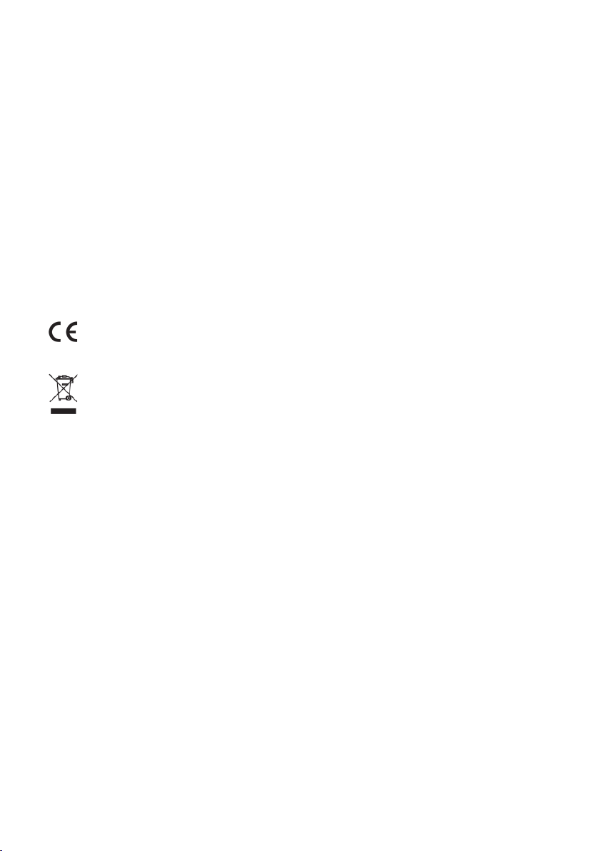
1.1.5 Ceramic capacitors
Ceramic capacitors are used for the separation of DC voltage and are mainly utilized with high frequencies.
Fig. 1.13: The component symbol is on the left and for information,
the circuit diagram symbol of the silicon solar cell on the right;
the experimental package contains one only.
Fig. 1.14: The component symbol is on the left and for information, the
circuit diagram symbol of the 100-pf ceramic capacitor on the right; the
experimental package contains one only.
Fig. 1.15: The component symbol is on the left and for information, the
circuit diagram symbol of the 220-pf ceramic capacitor on the right; the
experimental package contains two of them.
Fig. 1.16: The component symbol is on the left and for information,
the circuit diagram symbol of the 1-nf ceramic capacitor on the right;
the experimental package contains three of them.
Fig. 1.17: The component symbol is on the left and for information, the
circuit diagram symbol of the 10-nf ceramic capacitor on the right; the
experimental package contains three of them.
15
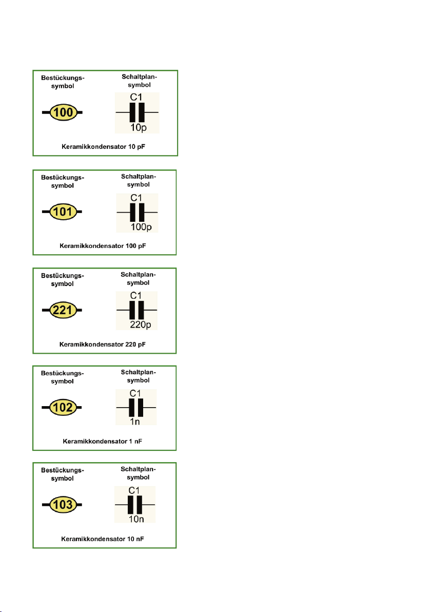
Fig. 1.18: The component symbol is on the left and for information, the
circuit diagram symbol of the 100-nf ceramic capacitor on the right; the
experimental package contains three of them.
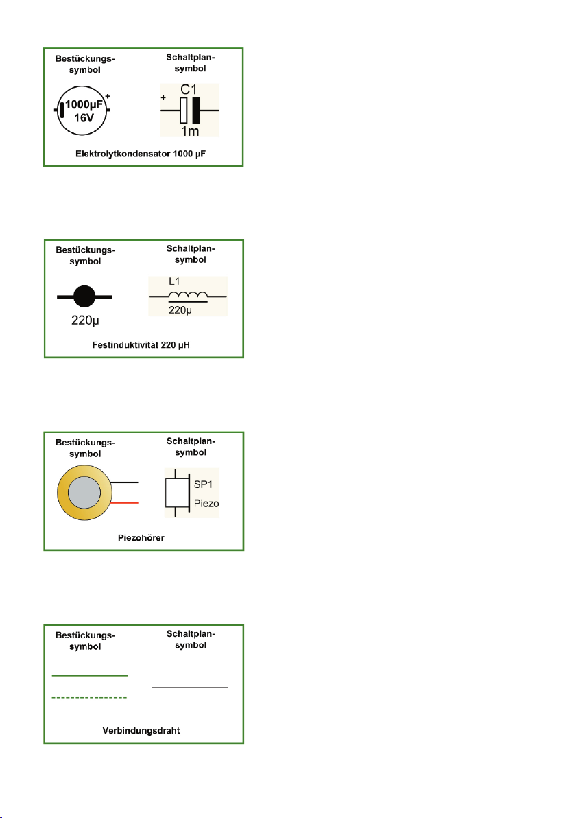
1.1.6 Electrolytic capacitors
Electrolytic capacitors are used for the separation of DC voltage and for short-term storage of electrical
energy. They are mainly utilized with low frequencies.
Fig. 1.19: The component symbol is on the left and for information, the
circuit diagram symbol of a 1-μF electrolytic capacitor on the right; the
experimental package contains two of them.
Fig. 1.20: The component symbol is on the left and for information, the
circuit diagram symbol of a 10-μF electrolytic capacitor on the right; the
experimental package contains four of them.
Fig. 1.21: The component symbol is on the left and for information, the
circuit diagram symbol of the 10-μF electrolytic capacitor on the right; the
experimental package contains one only.
Fig. 1.22: The component symbol is on the left and for information, the
circuit diagram symbol of a 100-μF electrolytic capacitor on the right; the
experimental package contains two of them.
16
Fig. 1.23: The component symbol is on the left and for information, the
circuit diagram symbol of the 1.000-μF electrolytic capacitor on the right;
the experimental package contains one only.
1.1.7 Fixed value inductance
Inductors are mainly used in resonant circuits or for screening purposes.
Fig. 1.24: The component symbol is on the left and for information,
the circuit diagram symbol of a 220-μH-fixed inductor on the right;
the experimental package contains one only.
1.1.8 Piezo element
The Piezo horn is used to reproduce or generate audio signals.
Fig. 1.25: The component symbol is on the left and for information,
the circuit diagram symbol of the Piezo horn included on the right;
the experimental package contains one only.
1.1.9 Jumper wire
Jumper wires are used to create the required electrical connections, in our case in the form of wire bridges.
Fig. 1.26: The component symbol is on the left and for information, the
circuit diagram symbol of a connection on the right; the experimental
package contains one meter of insulated jumper wire.

17
1.1.10 Battery clip 9-V block
A battery clip is used to connect the battery to the circuit.
Fig. 1.27: Component symbol of the enclosed battery clip for a 9 V block
battery, there is no individual circuit diagram symbol for this;
the experimental package contains one only.
1.1.11 Battery holder 1.5 V AA
A battery holder is used to connect the battery to the circuit.
Fig. 1.28: Component symbol of the enclosed 1.5 AA battery holder, there
is no individual circuit diagram symbol for this; the experimental package
contains two of them.
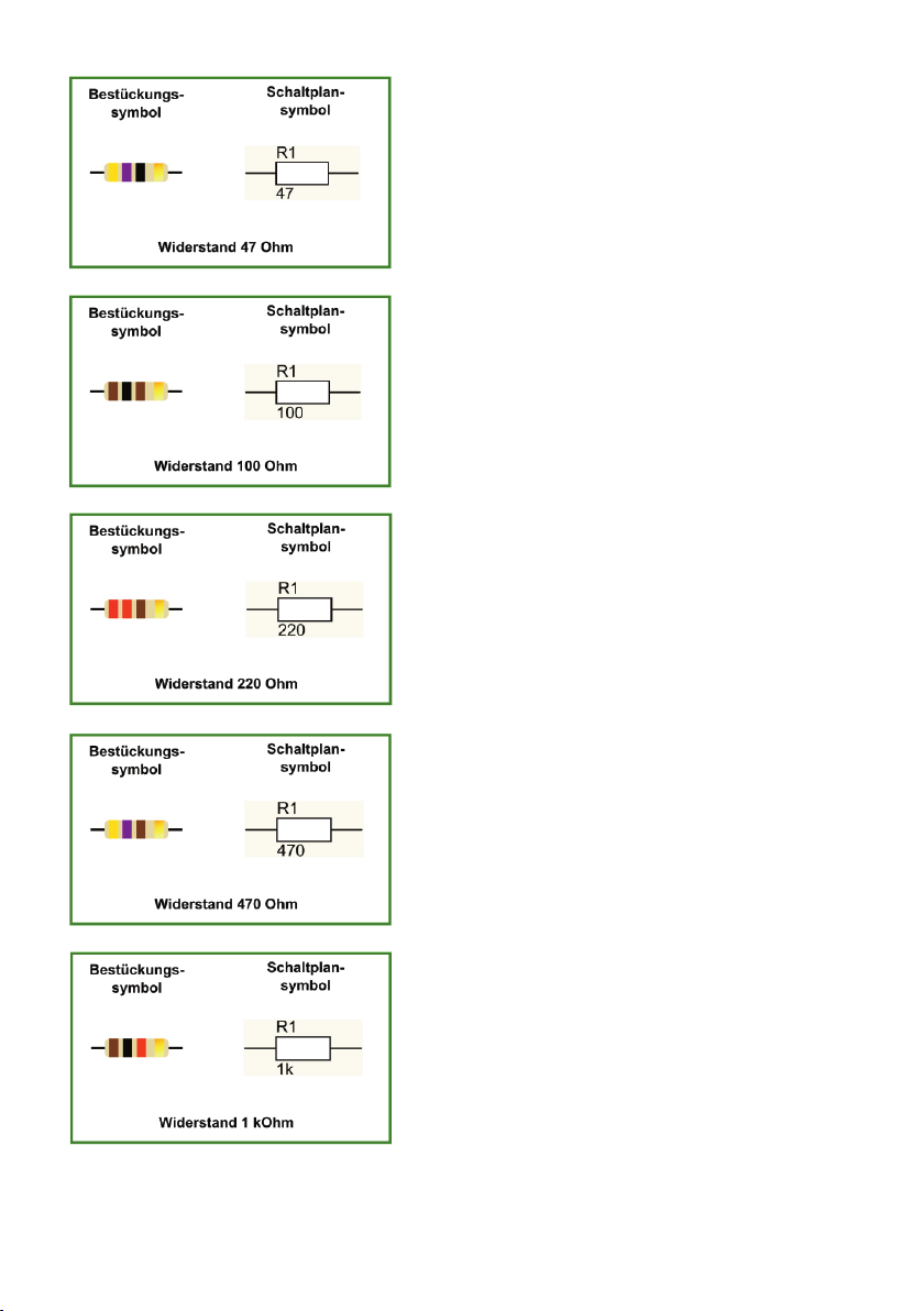
1.1.12 Resistors
Resistors are used to set the voltage potential to the required value.
Fig. 1.29: The component symbol is on the left and for information, the
circuit diagram symbol of the 10-Ω resistor on the right; the experimental
package contains one only.
Fig. 1.30: The component symbol is on the left and for information, the
circuit diagram symbol of the 22-Ω resistor on the right; the experimental
package contains one only.
18
Fig. 1.31: The component symbol is on the left and for information, the
circuit diagram symbol of the 47-Ω resistor on the right; the experimental
package contains one only.
Fig. 1.32: The component symbol is on the left and for information, the
circuit diagram symbol of the 100-Ω resistor on the right; the experimental
package contains two of them.
Fig. 1.33: The component symbol is on the left and for information, the
circuit diagram symbol of the 220-Ω resistor on the right; the experimental
package contains two of them.
Fig. 1.34: The component symbol is on the left and for information, the
circuit diagram symbol of the 470-Ω resistor on the right; the experimental
package contains one only.
Fig. 1.35: The component symbol is on the left and for information, the
circuit diagram symbol of the 1-kΩ resistor on the right; the experimental
package contains four of them.
19
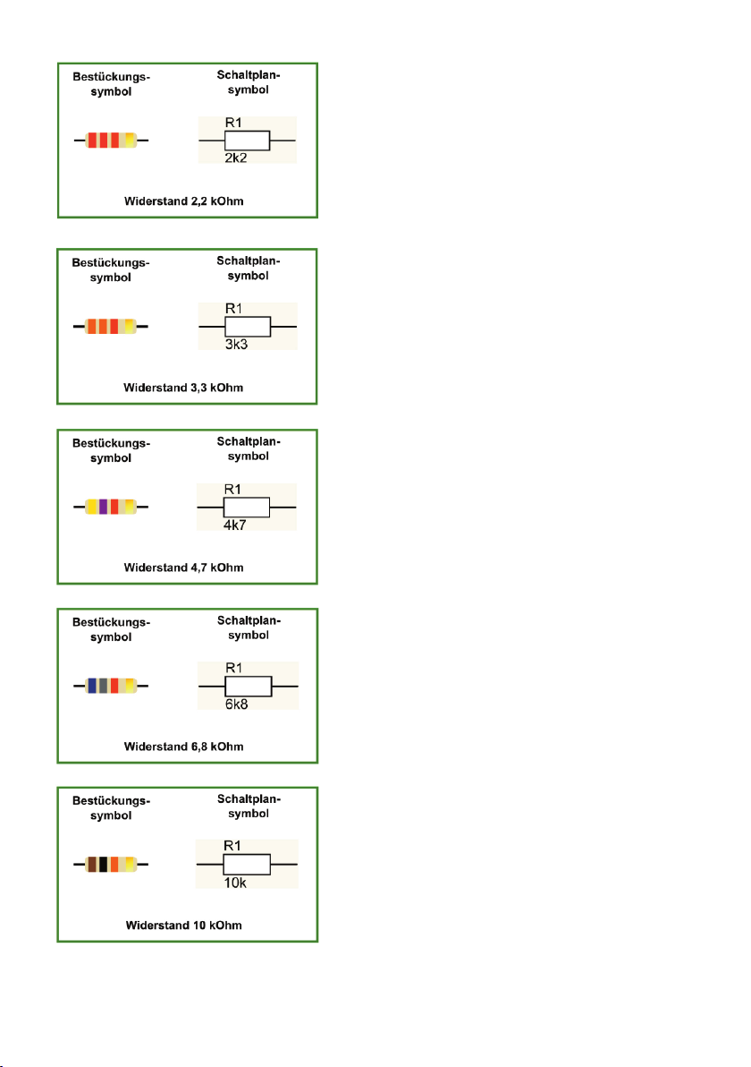
Fig. 1.36: The component symbol is on the left and for information, the
circuit diagram symbol of the 2.2-kΩ resistor on the right; the experimental
package contains three of them.
Fig. 1.37: The component symbol is on the left and for information, the
circuit diagram symbol of the 3.3-kΩ resistor on the right; the experimental
package contains one only.
Fig. 1.38: The component symbol is on the left and for information, the
circuit diagram symbol of the 4.7-kΩ resistor on the right; the experimental
package contains two of them.
Fig. 1.39: The component symbol is on the left and for information, the
circuit diagram symbol of the 6.8-kΩ resistor on the right; the experimental
package contains one only.
Fig. 1.40: The component symbol is on the left and for information, the
circuit diagram symbol of the 10-kΩ resistor on the right; the experimental
package contains four of them.

20
Fig. 1.41: The component symbol is on the left and for information, the
circuit diagram symbol of the 22-kΩ resistor on the right; the experimental
package contains four of them.
Fig. 1.42: The component symbol is on the left and for information, the
circuit diagram symbol of the 47-kΩ resistor on the right; the experimental
package contains two of them.
Fig. 1.43: The component symbol is on the left and for information, the
circuit diagram symbol of the 56-kΩ resistor on the right; the experimental
package contains one only.
Fig. 1.44: The component symbol is on the left and for information, the
circuit diagram symbol of the 100-kΩ resistor on the right; the experimental
package contains four of them.
Fig. 1.45: The component symbol is on the left and for information, the
circuit diagram symbol of the 220-kΩ resistor on the right; the experimental
package contains four of them.
21
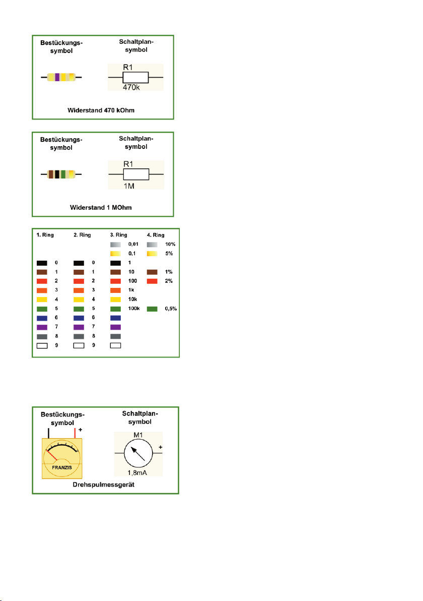
Fig. 1.46: The component symbol is on the left and for information, the
circuit diagram symbol of the 470-kΩ resistor on the right; the experimental
package contains two of them.
Fig. 1.47: The component symbol is on the left and for information, the
circuit diagram symbol of the 1-MΩ resistor on the right; the experimental
package contains one only.
Fig. 1.48: Colour chart for the coding of the resistors
1.1.13 Moving-coil instrument
A moving-coil instrument is used to indicate the level of direct current by means of the needle deflection.
Fig. 1.49: The component symbol is on the left and for information, the
circuit diagram symbol of the moving-coil instrument included on the
right; the experimental package contains one only.

22
1.2 Tips
1.2.1 Successful equipping
A perfect connection is the alpha and omega for your experiment to succeed. But a problem with a contact
in an electrical system brings even a car to a halt.
Make sure that the jumper wires of components are all free of grease and dirt. The ends should be straight-
ened. The board‘s contact holes are sometimes very tight, especially in the beginning. A bit of force and
skilfulness are needed to insert the wire ends into the board. The best bet is to use a pair of good tweezers
for support. A part of the wire ends must be fitted into the plug contact. If you are not sure, pull a bit on the
wire. If the wire remains tight in the board, it is properly inserted.
1.2.2 Simple bending jig
Tidy home, tidy mind! In our case this means that clean angled jumper wires will at least let you keep
track and increase the probability that everything is wired correctly. You can only successfully reproduce
our experiment, if everything is properly connected. A very handy tool that is equally small is shown in
Fig. 1.50. You can easily make it yourself using a standard perforated board. Use it to create clean angled
jumper wires with widths of 1 x spacing to 12 x spacing
Fig. 1.50: Bending jig, cut from a perforated board
1.2.3 Acoustic panel
The Piezo element enclosed works also, if it is not installed in a suitable housing; however, sensitivity
might be a bit underwhelming. A sound plate is easy to make and it significantly enhances its performance.
Fig. 1.51 has an example. A hole is cut out of the centre of a round metal or plastic plate. The Piezo element
will be fitted in (the outer diameter is about 100mm, the cut-out for the Piezo element should be 24mm
exactly). Use epoxy resin, which has good bonding capabilities. Installing it into the lid of a matching box
(dimensions as above, the can’s height is irrelevant) is the best solution however. The level of sensitivity
achieved by this, is comparable to the one of commercial crystal headphones.
Table of contents


