7
Speed change
Fig.6
To change the speed, first switch off the tool and then
slide the speed change lever to the "2" side for high
speed or, "1" side for low speed. Be sure that the speed
change lever is set to the correct position before
operation. Use the right speed for your job.
CAUTION:
•
Always set the speed change lever fully to the
correct position. If you operate the tool with the
speed change lever positioned halfway between the
"1" side and , "2" side, the tool may be damaged.
• Do not use the speed change lever while the tool is
running. The tool may be damaged.
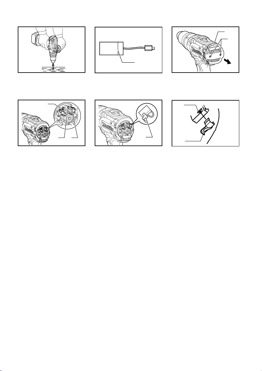
Selecting action mode
Fig.7
This tool has an action mode change lever. For drilling,
slide the action mode change lever to the left ( symbol).
For screwing, slide the action mode change lever to the
right ( symbol).
NOTE:
• When changing the position from " " to " ", it
may be a little difficult to slide the mode change
lever. At this time, switch on and run the tool for a
second at the " " position, then stop the tool and
slide to your desired position.
CAUTION:
• Always slide the action mode change lever all the
way to your desired mode position. If you operate
the tool with the lever positioned halfway between
the mode symbols, the tool may be damaged.
• Do not use the action mode change lever while the
tool is running. The tool may be damaged.
Adjusting the fastening torque
Fig.8
The fastening torque can be adjusted in 16 steps by
turning the adjusting ring so that its graduations are
aligned with the pointer on the tool body.
First, slide the action mode change lever to the position
of symbol.
The fastening torque is minimum when the number 1 is
aligned with the pointer, and maximum when the
marking is aligned with the pointer. The clutch will slip at
various torque levels when set at the number 1 to 16.
Before actual operation, drive a trial screw into your
material or a piece of duplicate material to determine
which torque level is required for a particular application.
NOTE:
•
The adjusting ring does not lock when the pointer is
positioned only halfway between the graduations.
ASSEMBLY
CAUTION:
• Always be sure that the tool is switched off and the
battery cartridge is removed before carrying out
any work on the tool.
Installing side grip (auxiliary handle)
Fig.9
Always use the side grip to ensure operating safety.
Insert the side grip so that the protrusions on the grip
base and steel band fit in between the grooves on the
tool barrel. Then tighten the grip by turning clockwise.
Installing or removing driver bit or drill bit
Fig.10
Turn the sleeve counterclockwise to open the chuck
jaws. Place the bit in the chuck as far as it will go. Turn
the sleeve clockwise to tighten the chuck. To remove the
bit, turn the sleeve counterclockwise.
Installing bit holder
Fig.11
Fit the bit holder into the protrusion at the tool foot on
eithher right or left side and secure it with a screw.
When not using the driver bit, keep it in the bit holders.
Bits 45 mm long can be kept there.
Hook
Fig.12
The hook is convenient for temporarily hanging the tool.
This can be installed on either side of the tool.
To install the hook, insert it into a groove in the tool
housing on either side and then secure it with a screw.
To remove, loosen the screw and then take it out.
OPERATION
Screwdriving operation
Fig.13
First, slide the action mode change lever so that it points
to the marking. Adjust the adjusting ring to the proper
torque level for your work. Then proceed as follows.
Place the point of the driver bit in the screw head and
apply pressure to the tool. Start the tool slowly and then
increase the speed gradually. Release the switch trigger
as soon as the clutch cuts in.
NOTE:
• Make sure that the driver bit is inserted straight in
the screw head, or the screw and/or bit may be
damaged.
• When driving wood screws, predrill pilot holes to
make driving easier and to prevent splitting of the
workpiece. See the chart.