Manitowoc OES 6.08 mini User manual

Part No. OESMINI-INM REV F 08/13 (8197325)
Installation Manual
Installation and Maintenance Instructions
The MINI
Model Number: OES 6.08 mini, OES 3.10 mini, OES 6.10 mini,
OES 10.10 mini, OES 6.10 2in1 mini
Cleveland Range, LLC
1333 East 179th Street
Cleveland, Ohio 44110
Phone: (216) 481-4900
Fax: (216) 481-3782
www.clevelandran
g
e.com

ALL SERVICE MUST BE PERFORMED BY A QUALIFIED
CLEVELAND RANGE AUTHORIZED TECHNICIAN.
This Installation Manual is a part of your new MINI. You must keep and maintain it
for the entire life span of your MINI and pass it on to the next owner of the MINI.
KEEP THIS MANUAL FOR REFERENCE
This manual may be subject to new technical developments, modifications, and unforeseen errors.
DO NOT OPERATE OR ATTEMPT TO OPERATE THIS APPLIANCE OR ANY ACCESSORIES WITHOUT READING
COMPLETELY AND FULLY UNDERSTANDING THIS MANUAL
The MINI Convotherm Combi/Oven-Steamers are intended for other than household use.
FOR YOUR SAFETY
Do not store or use gasoline or
other flammable vapors or
liquids in the vicinity of this or
any other appliance.
Disconnect power at the main external power switch before servicing or repairing a MINI.
Failure to disconnect power can result in death, injury, and property damage.
Improper installation, adjustment, alteration,
service or maintenance can cause property
damage, injury or death. Read the
installation, operating and maintenance
instructions thoroughly before installing or
servicing this equipment.
Do not connect the MINI Combi/Oven-Steamer drain connection to
any drain material that cannot sustain 140oFahrenheit.
Using drain material that cannot withstand 140oFahrenheit can
result in injury, equipment damage, and property damage.
Improper installation, adjustment, alteration, service, or maintenance of this appliance, or installation of
a damaged appliance can result in DEATH, INJURY, EQUIPMENT DAMAGE, and void the warranty.
NEVER install damaged appliances, equipment, or accessories. This unit may only be installed with
Cleveland Range provided legs or stands. Installation in any other manner can result in DEATH,
INJURY, EQUIPMENT DAMAGE, and void the warranty. NEVER INSTALL THIS UNIT WITHOUT
LEGS UNLESS IT IS INSTALLED ON A CLEVELAND RANGE STAND SPECIFYING THAT LEGS
ARE NOT REQUIRED IN ITS INSTRUCTIONS.
ALWAYS have installation and service performed by qualified Cleveland Range authorized personnel.

CONVOTHERM STATEMENT OF POLICIES
LIMITED WARRANTY
CONVOTHERM products are warranted to the original purchaser to be free from defects in materials and workmanship
under normal use and service for the standard warranty period of one year from date of installation or 18 months from date of
shipment, whichever comes first.
CONVOTHERM agrees to repair or replace, at its option, f.o.b. factory, any part which proves to be defective due to defects
in material or workmanship during the warranty period, providing the equipment has been unaltered, and has been
PROPERLY INSTALLED, MAINTAINED, AND OPERATED IN ACCORDANCE WITH THE CONVOTHERM OWNER’S
MANUAL.
CONVOTHERM agrees to pay any FACTORY AUTHORIZED EQUIPMENT SERVICE AGENCY (within the continental
United States, and Hawaii) for reasonable labor required to repair or replace, at our option, f.o.b. factory, any part which
proves to be defective due to defects in material or workmanship, during the labor warranty period. This warranty includes
travel time not to exceed two hours and mileage not to exceed 50 miles (100 miles round-trip), BUT DOES NOT INCLUDE
POST START-UP, TIGHTING LOOSE FITTINGS, MINOR ADJUSTMENTS, MAINTENANCE, CLEANING OR DESCALING.
The standard labor warranty allows factory payment of reasonable labor required to repair or replace such defective parts.
CONVOTHERM will not reimburse the expense of labor required for the repair or replacement of parts after the standard
warranty period, unless an Extended Labor Warranty Contract has been purchased to cover the equipment for the balance of
the warranty period from the date of equipment installation, start-up, or demonstration.
PROPER INSTALLATION IS THE RESPONSIBILITY OF THE DEALER, THE OWNER-USER, OR INSTALLING
CONTRACTOR, AND IS NOT COVERED BE THIS WARRANTY. Many local codes exist, and it is the responsibility of the
owner and installer to comply with these codes. CONVOTHERM equipment is built to comply with applicable standards for
manufacturers, including UL, AGA, NSF, ASNE/Ntl. Bd, CSA, CGA, ETL and others.
STEAM GENERATOR MAINTENANCE IS THE RESPONSIBILITY OF THE OWNER-USER AND IS NOT COVERED BY
THIS WARRANTY. The use of good quality feed water is the responsibility of the Owner-User (see Water Quality
Recommendations below). THE USE OF POOR QUALITY FEED WATER WILL VOID EQUIPMENT WARRANTIES. Steam
Generator maintenance supplies, including gaskets, are not warranted beyond the first 90 days after the date the equipment is
placed into service. Preventive maintenance records must be available showing descaling per applicable CONVOTHERM
Operator Manual for Boiler Proration Program considerations.
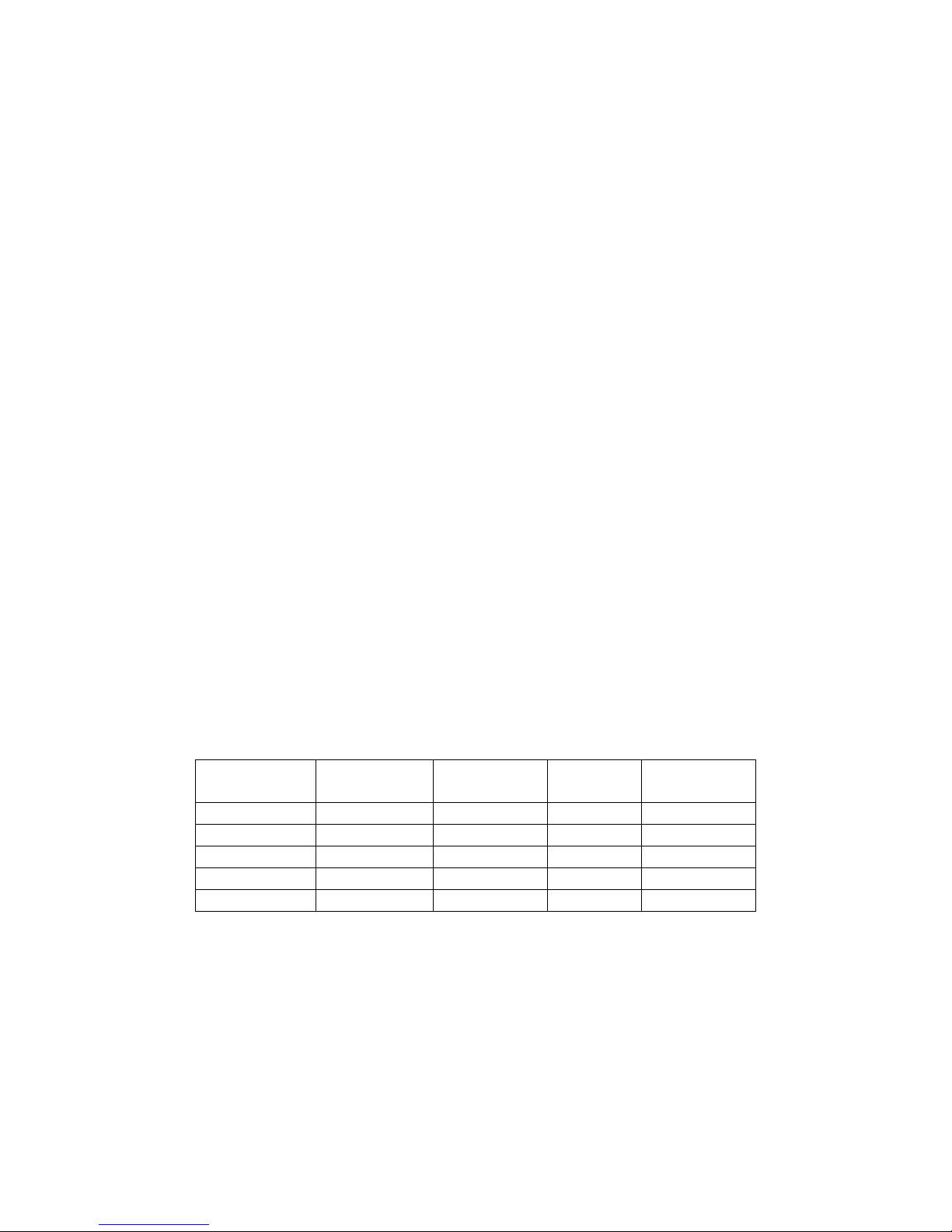
WATER QUALITY RECOMMENDATIONS (NEW)
TDS………………………50-125 ppm pH Factor…………..7.0-8.5
Total Alkalinity…………..50-100 ppm Free Chlorine………< 0.1 ppm
Silica……………………..<13 ppm Hardness…………...50-100 ppm (3-6gpg)
Chloride………………….< 25ppm Water Pressure……35-80 psi
The foregoing shall constitute the sole and exclusive remedy of original purchaser and the full liability of CONVOTHERM for
any breach of warranty. THE FOREGOING IS EXCLUSIVE AND IN LIEU OF ALL OTHER WARRANTIES, WHETHER
WRITTEN, ORAL. OR IMPLIED, INCLUDING ANY WARRANTY OF PERFORMANCE, MERCHANTABILITY, OR FITNESS
FOR PURPOSE, AND SUPERSEDES AND EXCLUDES ANY ORAL WARRANTIES OR REPRESENTATIONS, OR
WRITTEN WARRANTIES OR REPRESENTATIONS, NOT EXPRESSLY DESIGNATED IN WRITING AS A “WARRANTY” OR
“GUARANTEE” OF CONVOTHERM MADE OR IMPLIED IN ANY MANUAL, LITERATURE, ADVERTISING BROCHURE OR
OTHER MATERIALS.
CONVOTHERM liability on any claim of any kind, including negligence, with respect to the goods or services covered
hereunder, shall in no case exceed the price of the goods or services, or part thereof, which gives rise to the claim. IN NO
EVENT SHALL CONVOTHERM BE LIABLE FOR SPECIAL, INCIDENTAL, OR CONSEQUENTIAL DAMAGES, OR ANY
DAMAGES IN THE NATURE OF PENALTIES.
LIMITED EXTENDED WARRANTY COVERAGE
The purchase of a Limited Extended Warranty Contract extends the standard warranty coverage to the purchased period of time (one to two
years) from the date of installation, start-up, or demonstration, whichever is sooner.
*An additional two years Parts and Labor Warranty can be purchased with each piece of CONVOTHERM equipment for an additional 3.5%
of the List Price per year. The 3.5% of list price charge will be the net invoice amount for each year of extended warranty purchased.
- Extended warranty must be purchased at the same time the equipment is purchased.
- Extended Warranty has the same exclusions as stated in our standard warranty.


INSTALLATION OF THE MINI
Table of Contents
Chapter Page
1 GENERAL INFORMATION………………………………………………………………….. 1
A. Product Information………………………………………………………………………... 1
B. Model Number…………………………………….………………………………………... 1
C. Serial Number and Equipment Record………………….………………………………. 1
D. Product Information Plate…………………………………….…………………………… 1
2 INSTALLATION INSTRUCTIONS………………………………………………………….. 2
A. Laws, Codes and Regulations.…………………………………………………………… 2
B. Inspect for Shipping Damage…………………………………………............................ 2
C. General Instructions……………………………………………………………………….. 3
D. Install the MINI………………….………………………………………………………...... 4
1. Select a Location for the MINI……….……………………………………………...… 4
2. Exhaust Hood Requirements………………………………………………………….. 4
3. Dimensions and Clearances………………………………………………………...… 5
4. Connections……………………..…………………………………………………...… 8
5. Sensible and Latent Heat Values…..……………………………………………...…
6. Air Supply………………………………………………………………………………. 12
12
E. Water Connections for the MINI………………………………………………………...... 13
1. Install Water Supply……………………………………………………………………. 13
2. Water Supply Requirements…………………………………………………………... 13
3. Connect Water Supply Lines………………………………………………………….. 14
4. Test Water Supply Lines………………………………………………………………. 14
F. Electric Connections for the MINI……………………………………………………...… 17
1. Install Electric Power Lines……………………………………………………………. 17
2. Electrical Connection Data…………………………………………………………….. 17
G. General Information for ALL MINIs…………………………………………………….… 18
H. Install Free Air Vented Drain Lines from the MINI to the Existing Floor Drain…..….. 18
3 STARTUP PROCEDURE……………………………………………………………………. 20
A. Installation Check List……………………………………………………………………... 22
B. In the Event of a Power Failure…………………………………………………………... 22
C. Startup Procedure…………………………………………………………………………. 22

1
CHAPTER 1
GENERAL INFORMATION
A. Product Information
Cleveland Range assigns two product identification numbers to each MINI: a model number and a serial
number. The model number identifies the product characteristics. The serial number identifies the
individual unit.
B. Model Number
1. This manual covers installation of The MINI Convotherm Combi/Oven-Steamer.
2. For further information, contact your Cleveland Range sales representative or Cleveland Range.
C. Serial Number and Equipment Record
During manufacture, MINIs are assigned individual serial numbers. Please provide the following
information when you contact Cleveland Range or a qualified Cleveland Range authorized service
representative:
Serial Number________________________________________________________________
(Write the Serial Number of your MINI here.)
Model Number________________________________________________________________
(Write the Model Number of your MINI here.)
D. Product Information Plate
The Product Information Plate on the left side of the unit lists the model, serial number, electric, and
wiring requirements of the appliance.

2
Operating this appliance out of level can cause DEATH, INJURY, and EQUIPMENT DAMAGE.
This appliance must be level both front-to-back and side-to-side in all installations.
NEVER operate this appliance out of level.
If this appliance is suspected to be out of level, shut it down at once and call your qualified
Cleveland Range authorized service agency immediately.
CHAPTER 2 INSTALLATION INSTRUCTIONS
A. Laws, Codes, and Regulations
This equipment should be installed only by qualified, professional plumbers, pipe fitters, and
electricians.
1. The installation of this appliance must conform with:
a. The National Electrical Code, ANSI/NFPA 70 (latest edition), or the Canadian Electrical
Code, CSA C22.2, or local codes, as applicable.
When installed, the appliance must be electrically grounded in accordance with the
above.
NOTE: This appliance is not GFI (GFCI) compatible.
b. The Food Code (latest edition) of the Food and Drug Administration (FDA).
2. This equipment is to be installed with adequate backflow protection to comply with applicable
federal, state and local codes.
3. This equipment is to be installed to comply with the applicable federal, state, or local plumbing
codes. Water and waste piping connections shall comply with the latest edition of the international
plumbing code, International Code Council (ICC) or the uniform Plumbing Code, International
Association of Plumbing and Mechanical Officials (IAPMO)
4. Installation instructions must be read in their entirety before starting installation of this
appliance. This includes the separate installation instructions provided with accessories such
as Cleveland Range stands designed to be used with the MINI.
5. Install this appliance according to the policies and procedures outlined in this manual.
6. Installation must comply with all local fire and health codes.
B. Inspect for Shipping Damage
If the appliance is damaged or damage is suspected:
1) Submit a Damage Claim to the Shipper immediately.
2) Inform your dealer at once.
3) Inform Cleveland Range in writing within three (3) days.
Improper installation, adjustment, alteration, service, or maintenance of this appliance, or installation of
a damaged appliance can result in DEATH, INJURY, EQUIPMENT DAMAGE, and void the warranty.
NEVER install damaged appliances, equipment, or accessories. This unit may only be installed with
Cleveland Range provided legs or stands. Installation in any other manner can result in DEATH,
INJURY, EQUIPMENT DAMAGE, and void the warranty. NEVER INSTALL THIS UNIT WITHOUT
LEGS UNLESS IT IS INSTALLED ON A CLEVELAND RANGE STAND SPECIFYING THAT LEGS
ARE NOT REQUIRED IN ITS INSTRUCTIONS.
ALWAYS have installation and service performed by qualified Cleveland Range authorized personnel.

3
All clearance requirements above, below, and around the MINI are the same for non-
combustible locations as for combustible locations.
Failure to maintain required clearances and additional distances as needed can result
INJURY and EQUIPMENT DAMAGE.
Consult manufacturers’ literature, and sales and service agencies as needed.
Operating an out of level MINI can cause DEATH, INJURY, and EQUIPMENT DAMAGE.
MINIs must be level both front-to-back and side-to-side in all installations.
NEVER operate an out of level MINI.
If a MINI is suspected to be out of level, shut it down at once and call you qualified
Cleveland Range authorized service agency at once.
C. General Instructions
1. Select the MINI’s operating location.
2. Only install the MINI with the legs provided or with a Cleveland Range Stand designed
specifically for a MINI. Never install this unit without legs unless it is installed on a Cleveland
Range stand specifying that legs are not required in its instructions.
3. Complete the water, drain, and electric lines before positioning and leveling the MINI.
4. Position and level the MINI.
5. Connect the utility lines after positioning and leveling the MINI.
6. Call Cleveland Range at 216-481-4900 for the Free Start-Up Program’s Performance Checkout.
7. After Setup and Performance Checkout, the MINI should provide years of reliable operation.
Improper lifting can result in DEATH, INJURY, AND EQUIPMENT DAMAGE.
Use enough workers with training and experience lifting heavy equipment to place
MINIs on supporting surfaces, and lift and handle MINIs and accessories.

4
D. Install the MINI
1. Select a Location for the MINI
a. For safe and efficient operation, observe the following criteria when selecting an
operating location for a MINI
b. Transport the MINI on its pallet.
c. Passages and doors must be high enough and wide enough for a MINI and its pallet. See
Table 2-1.
d. Location selected must be capable of supporting a MINI. See Table 2-1.
e. The area MUST be free from and clear of combustible materials.
f. KEEP THE MINI AREA FREE AND CLEAR FROM COMBUSTIBLES.
g. Level the floor if needed.
h. The operating surface must be level enough to allow leveling a MINI with its adjustable
legs, or those provided with the appropriate Cleveland Range provided stand.
i. A MINI MUST be level both front to back and side to side.
j. Position the MINI so it will not tip or slide.
k. The ambient temperature should be within 40° and 95° F.
l. Proper air supply for ventilation is REQUIRED for and CRITICAL to safe, efficient
operation of a MINI.
m. Operating Clearances: Sides and Rear - 3".
n. Service Clearance: Above - 20”.
o. Allow for sufficient distance if a "high heat source" (e.g. broiler) is located next to the unit
p. Allow for sufficient clearance on left side for service access. Contact Cleveland Range at
216-481-4900 for recommendations.
q. Allow extra clearance on the side if the appliance has the optional hand shower.
r. Installation must comply with all local fire and health codes.
s. Do not install the MINI directly over a drain. Steam rising up out of the drain will adversely
affect operation, hamper cooling air circulation, and damage electrical and electronic
components.
t. Do not obstruct the flow of ventilation air. Make sure the air vents of the MINI are not blocked.
TABLE 2-1 WEIGHT AND DIMENSIONS INCLUDING PALLET AND CRATE*
The MINI
MODEL WEIGHT WIDTH DEPTH HEIGHT
6.08 143 lb 22.84” 32.65” 31.5”
3.10 190 lb 25.6” 36.5” 32.1”
6.10 190 lb 25.6” 36.5” 32.1”
10.10 215 lb 22.84” 35.83” 41.93”
6.10 2in1 310 lb 22.84” 36.81” 67.38”
2. Exhaust Hood Requirements
a. Install the MINI under an Exhaust Hood.
b. The exhaust hood must extend over the exhaust ports and meet the following requirements:
1) The Exhaust hood must be sized for the cumulative ventilation requirements of all the
appliances in the area under the hood, including the MINI.
2) If an existing hood cannot be used, a new one must be constructed over the MINI.
3) When determining hood size; include Operating Clearances of 3 inches sides and
rear, and Service Clearance of 20 inches overhead. See Table 2-2

5
START
STOP
KEY
SMART
STEAM COMBI RETHERMHOTAIR TEM P PROBETIME
COOKBOOK EDIT
ON
OFF
1234
5678
20.625"
24.00"
3.00"
20.276"
3.00"
3.00"
30.75"
180°
28.95"
22.66"
31.88"
TABLE 2-2 OPERATING WEIGHT AND DIMENSIONS*
The MINI
MODEL WEIGHT WIDTH DEPTH HEIGHT
6.08 110 lb 20.3” 31.3” 27.7”
3.10* 157 lb 20.3” 35.06” 29.27”
6.10* 157 lb 20.3” 35.06” 29.27”
10.10* 152 lb 20.3” 30.6” 33.7”
6.10 2in1* 218 lb 20.3” 31.6” 62.48”
*Weights presented presume that the user does not have a unit with the automatic
cleaning system option. The automatic cleaning system option increases both
shipping and operating weights 33 lbs. It increases both the shipping and operating
heights 33lbs of the 10.10 5.5”. Cleaning system increases depth of the 3.10 and 6.10
by .3”. the Easy Touch control option increases height by ~ 1 ¼ inches on all models
except the 2 in 1, where the Easy Touch is standard.
3. Dimensions and Clearances
OES6.08 Mini Dimensions and Clearances
Appliance must be installed level
Operating Clearances: Left-Right: 3”, Back: 3”
Service Clearance:Above: 20” (ventilation)
Allow extra clearance on the left side if the appliance has the optional hand shower.
Note: the Easy touch control option increases the height by approximately 1 ¼ inches.

6
OES 3.10/6.10 mini Dimensions and Clearances
Appliance must be installed level
Operating Clearances: Left-Right: 3”, Back: 3”
Service Clearance:Above: 20” (ventilation)
Allow extra clearance on the left side if the appliance has the optional hand shower.
Note: the Easy touch control option increases the height by approximately 1 ¼ inches.
Model Dimension (inches)
X Y Z
OES 3.10 mini 35.06 31.23 23.04
OES 6.10 mini 34.56 30.57 22.38
X
Y
Z

7
OES 10.10 mini Dimensions and Clearances
Appliance must be installed level
Operating Clearances: Left-Right: 3”, Back: 3”
Service Clearance:Above: 20” (ventilation)
Allow extra clearance on the left side if the appliance has the optional hand shower

8
OES 6.10 mini 2in1 Dimensions and Clearances
Appliance must be installed level
Operating Clearances: Left-Right: 3”, Back: 3”
Service Clearance:Above: 20” (ventilation)
Allow extra clearance on the left side if the appliance has the optional hand shower

9
4. Connections

10
OES 10.10 Connections

11
OES 6.10 mini 2in1 Connections

12
5. Sensible and Latent Heat Values
TABLE 2-2 HEAT OUTPUT
Model Number Heat Output kJ/h BTU/h
6.08 Sensible heat output 1100 1043
Latent heat output 1000 948
3.10 Sensible heat output 1450 1375
Latent heat output 1330 1261
6.10 Sensible heat output 1450 1375
Latent heat output 1330 1261
10.10 Sensible heat output 2030 1924
Latent heat output 1850 1754
6.10 2in1 Sensible heat output 2370 2247
Latent heat output 3700 3508
6. Air Supply
a. Keep all air intake vents clear, clean, and free of obstruction.
b. Observe all applicable codes for ventilation.

13
NOTICE
Using water outside the limits specified in this manual
without appropriate adjustment in the maintenance
schedule voids warranty coverage.
E. Water Connections for the MINI
1. Install Water Supply
a. Install the water supply before positioning the MINI.
b. Water supply line(s) must be designed so the MINI can be moved for service.
c. Construct all supply lines up to the point of installing the MINI.
d. Flush the water supply lines before connecting the MINI to the water supply lines.
e. Use of the supplied strainer is mandatory for warranty coverage. Use of a water filtration
system is recommended. Contact Cleveland Range at 216-481-4900 for details.
2. Water Supply Requirements
a. Water Quality
1) Check the quality of supply water (described below) before designing the water supply.
2) Contact a local water treatment specialist for on-premises water analysis.
3) Minimum feed water quality requirements are listed in Table 2-3.
4) Poor water supply quality degrades MINI performance.
5) Softened or chlorinated water damages the MINI by increasing corrosion. Carbon type
filters are required before water enters the MINI if supply water is softened or chlorinated.
6) If a water treatment system must be installed to achieve acceptable water quality, install it
BEFORE connecting the water supply lines to a MINI.
7) If analysis shows that supply water is below Minimum Water Quality:
EITHER a water treatment system and/or carbon filter must be installed in the line
feeding the spritzer,
OR the frequency of maintenance and cleaning must be increased beyond that
recommended in the maintenance schedule,
AND Contact your Cleveland Range sales representative for details on how to
provide water per Minimum Water Quality Requirements in Table 2-3, or how to
increase the frequency of maintenance and cleaning.
Table 2-3 Minimum Water Quality Requirements
Scale Forming Factors Concentrations must be:
Total Dissolved Solids 50-125 parts per million
Silica less than 13 parts per million
Alkalinity 50-100 parts per million
Hardness 50-100 parts per million (3-6gpg)
Corrosion-Causing Factors Concentrations must be:
Free Chlorine less than 0.1 parts per million
Chloride less than 25 parts per million
pH factor between 7.0-8.5
b. Water Supply System Pressure Requirements
The water supply must provide:
A minimum dynamic pressure of 35 psi (2.4 kg/cm2)
A maximum static pressure of 80 psi (4.1 kg/cm2).

14
3. Connect Water Supply Lines
The Installer/Owner is responsible for the correct water connection of the MINI. When connecting
water supply lines observe the following instructions, and any and all other applicable national,
state, and local codes and regulations:
a. Connect the MINI to COLD WATER
b. Never connect the MINI to HOT WATER! The condenser system will not work properly if
connected to HOT or WARM water.
c. The water supply must have a minimum dynamic (flow) pressure of 35 psi (2.4 kg/cm²) and a
maximum static pressure of 80 psi (4.1 kg/cm²).
d. If the static pressure is above 80 psi, a pressure regulator must be used and set at
approximately 50 psi. Pressure above 80 psi can damage solenoid valves.
e. MINIs have two connection points for incoming water. See Figure 2-1.
f. Stacked MINIs may be connected to the water supply as shown in Figure 2-2
g. 2 in 1 minis have 3 connection points. See Figure 2-3.
h. Water supply must meet the minimum requirements shown in the Warranty and Table 2-3.
Install a water treatment system as needed.
i. Installation Requirements:
1) Apply non-hardening pipe thread sealant to all the threaded connections except the ¾”
GHT Female (Garden Hose Thread or National Hose Thread) connections at the Water
Connection. GHT or NHT connections do not require pipe thread sealant.
2) Install a manual water shut-off valve (not provided) between main water supply lines and
MINI supply lines.
3) The National Sanitation Foundation (NSF) requires installation of a check-valve (or other
approved anti-backflow / anti-siphon device) (not provided) in all supply lines in
accordance with and as required by local, state, and national health, sanitation and
plumbing codes.
4) Check local codes to determine exactly what type of anti-backflow / anti-siphon device is
necessary to meet local requirements.
4. Test Water Supply Lines
a. Check all connections for proper tightness.
b. Remove rear and top panels to inspect water connections inside the MINI.
c. Open the water supply valves.
d. Check all lines and connections for leaks, both inside and outside the MINI.
e. Replace the top and rear panels and secure them to the MINI before starting the MINI.
This manual suits for next models
5
Table of contents
Other Manitowoc Oven manuals
Popular Oven manuals by other brands

SEVERIN
SEVERIN TOASTOFEN TO 2032 Dimensions

NEFF
NEFF B69FS5C.0A User manual and installation instructions

Hotpoint
Hotpoint SE661X/1 operating instructions

STODDART
STODDART Giorik Movair MTE5WRT SPECIFICATION, INSTALLATION & OPERATION MANUAL

Pkm
Pkm BIC3 I-GK-IX-2 instruction manual

Prima
Prima LPR802 manual