10
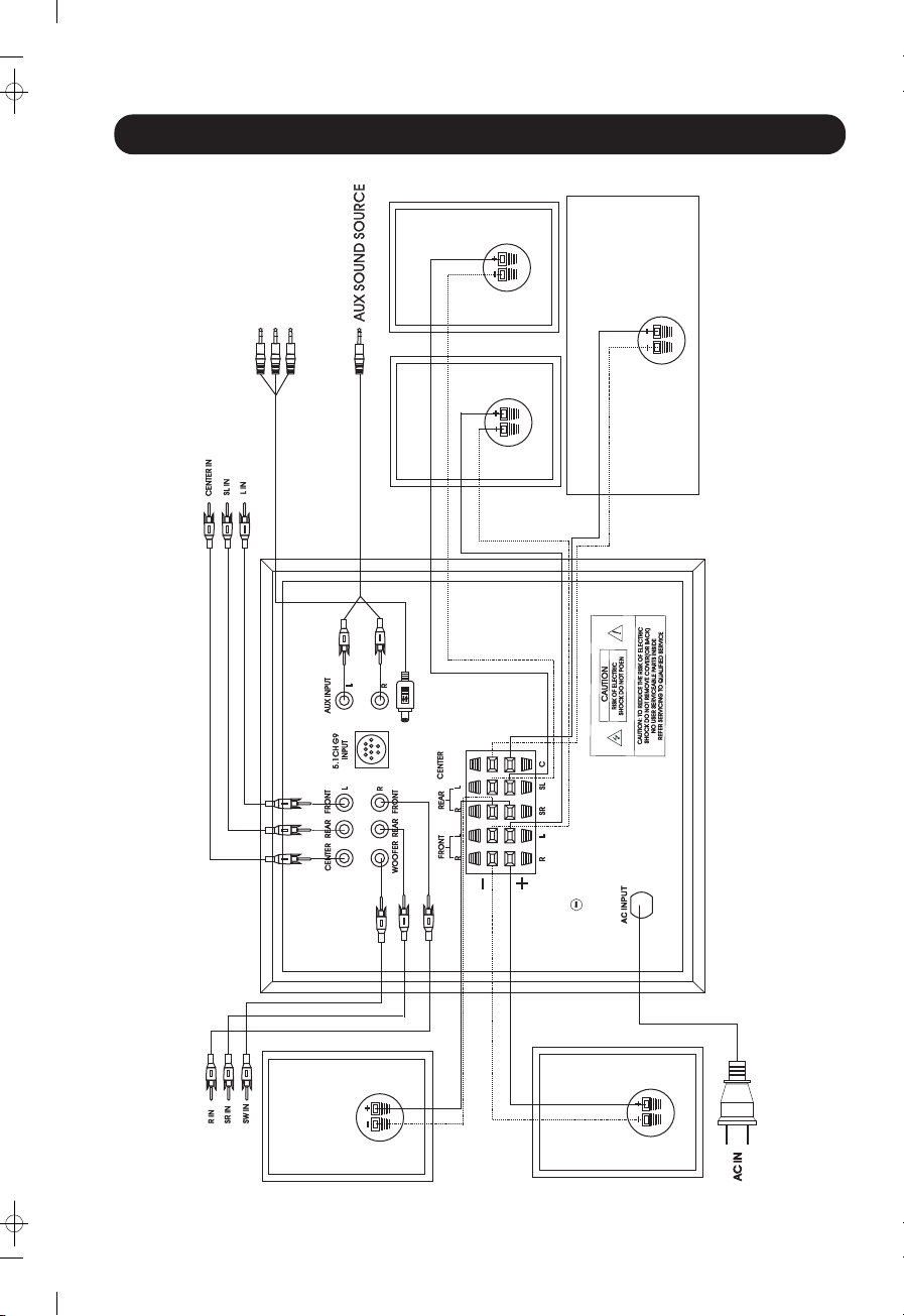
wThe AC-3(5 .1) input connectors on the subwoofer rear panel are for the devices those,
which are with the 5:1 channel outputs of front speakers, central speakers & subwoofer;
such as DVD.
wThe 5.1CH G9 input on the subwoofer is for the devices those are with the 5.1 channel
output that is with the terminal; such as a sound card for the computer.
wThe AUX input is for two sound channel devices such as CD. VCD & PC. Please refer to
their manual respectively when connecting those devices with this system.
1. The operative range of the remote Gontrol is 7 meters & the valid angle is 45 degrees from the
remote contro1 window on the main body of the system; Push the “POWER ON/OFF” button
on the remote controller to turn on the system, When the LED indicator turn into green color
from the red one, it means the power is on already.
2. When the sound source is a DVD, AC-3 or PC 5.1, please push the AC-3 button on the remote
controller. The LED function indicator will then be lit in red color that means the system is in the
AC-3 sound source input status. When the sound source is a PC or CD, please press the “AUX”
button on the remote controller. The LED function indicator will then be in green color, it means
the system is in the AUX sound source input status. (The operation also can be done by
pressing the “AC-3/AUX” function key on the front panel of the mam body of this device.)
3. Press the function key “VOLUME” to adjust the master volume. One also can adjust the volume
of front speakers, rear surround speakers and subwoofer accordingly by pressing the button of
“+” or “-” to satisfy his preference.
4. RESET: By pressing the “RESET” button, You can turn the speaker volum to the default
condition.
5. The function key “MUTE” is for shutting off the sound of the system rapidly. Press this key while
in playing, the sound will be shut off immediately. Press the key again to bring it back to the
original status.
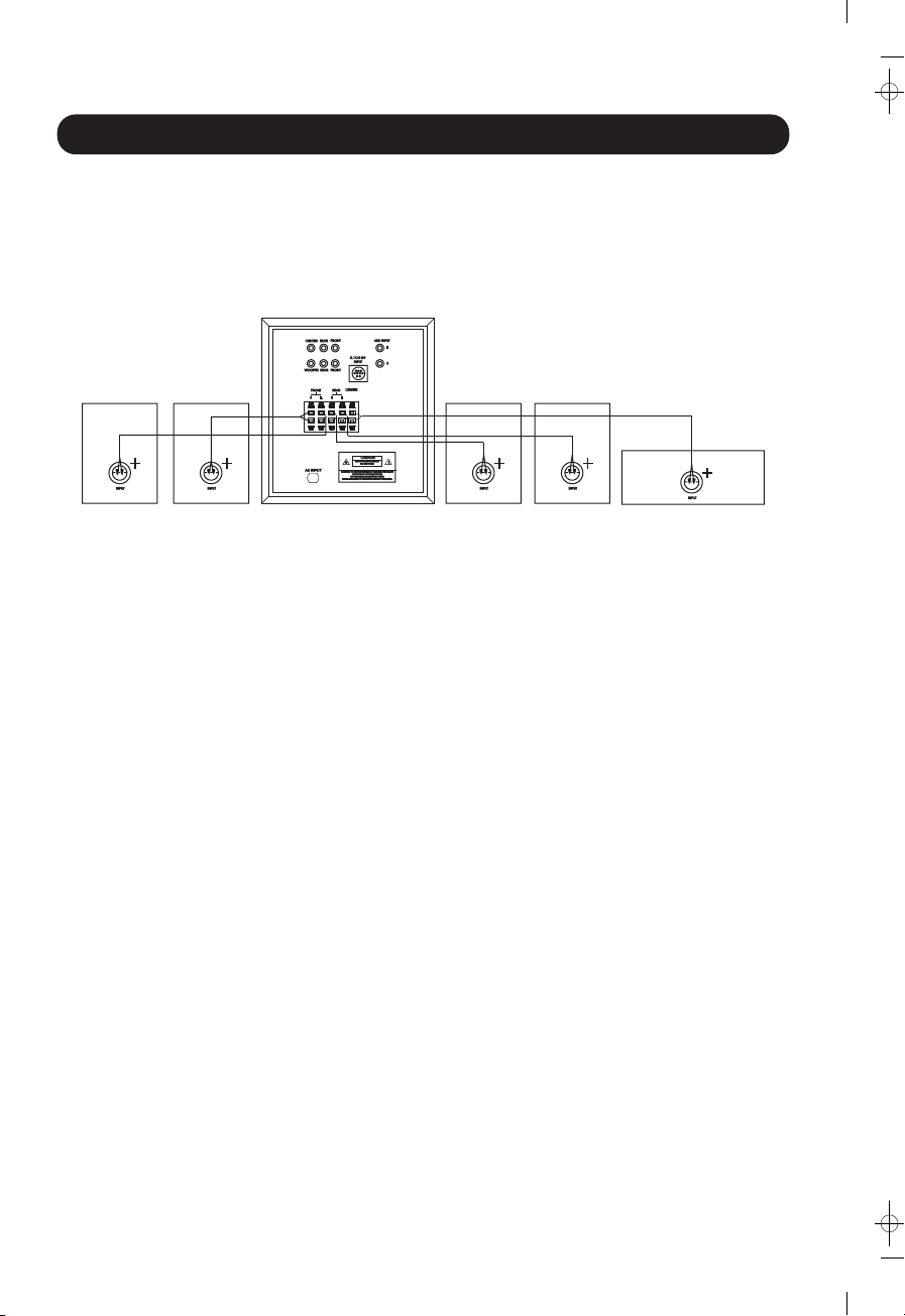
INSTALLATION THE SYSTEM
OPERATION MANUAL
11
1. Please adjust the volume to a proper level while in using. Otherwise, it may damage your
hearing or this device.
2.Please unplug the system when it will not be used for a long period of time.
1. SUBWOOFER IS NOT IN MOTION:
Firstly, check that if the subwoofer input is being well connected. Secondly, press the
“Woofer +” key on the remote controller to check if it is on. And then check the subwoofer
again.
2. NOSOUND IS BEING OUTPUT FORM THE WHOLE SYSTEM:
Check that if the power is on. And then press the “MUTE” key to find out it is in the mute
mode.
3. REMOTE CONTROLLER IS NOT IN FUNCTION:
a. Check the batteries first.
b. Check that if the remote control window
of transmitting/receibing is being blocked.
c. Shut down the system for 5 seconds at least, and then turn it on again;
the remote controller should be back to normal.
4. SOUND OF ELECTRICITY IMPACT FROM THE SPEAKER
WHEN TURNING THE SYSTEM ON:
The system is equipped with the function of restraining the electricity impact sound
occurred when it is being turned on. But the electrical circuit needs a few seconds to
become stable after the system is being turned on.
Therefore it is normal that there is still a slight impact sound occurred when we turn on the
system.
A large electricity impact sound will occur if we turn on the system again within two minutes
after turning it down. This is because that the restraining electrical circuit has not been
back to its normal status yet.
NOTICE
TROUBLESHOOTING