Marani Pro Audio PDA500PF Owner's manual

PDA500PF
PDA500PF is a complete solution dedicated to 1-way or 2-way self-powered loudspeakers. Designed to
meet different applications, it pro ides 2 channels with output power of 2x500W@4 Ohm or
2x250W@8 Ohm. In addition it offers a full set of added alue features such as on board DSP and
RS485 connection for monitoring and control ia dedicated PC software. To guarantee maximum
reliability, the PDA500PF includes a highly efficient uni ersal switch mode power supply with PFC
(Power Factor Correction) which pro ides a total 1kW power to the 2 output channels. The 2 output
stages use the well-known Pascal Class D SPRO2 module. The PDA500PF includes a set of sophisticated
processes for loudspeaker, implemented by the powerful M704 DSP running 48kHz/24bit [96 bits
precision for the internal intermediate processes] and high performance 24bit AD/DA Con erters.
Processes as Noise Gate, up to 512 taps FIR filters OR up to 48dB/Oct IIR Hp/Lp filters for X-o er,
parametric EQs per input and output sections, RMS compressor, alignment delay and All-Pass filters
are a ailable, all in all e erything needed to optimize a self-powered loudspeaker. Moreo er the
Clip/Limiter function per channel pro ides output monitoring to pre ent speaker damage with gentle
gain reduction at clip threshold, in addition to the efficient heat dissipation system and O er-Heat
protection which themsel es ensure a reliability without compromises. Furthermore the PDA500PF is
also equipped with a Dynamic Loudness function and an useful Pink/White noise generator. All setup
parameters for input mixing, DSP features and the limiter setting are accessible by using the remote
PC software.
A Powerful 512taps FIR is available for the System Phase Correctio , based o System Respo se
measureme t.

Features
Outstanding Performance
High power output: 2 x 500W @ 4Ω or 2 x 250W @ 8Ω
Switched-Mode Power Supply with PFC and auto oltage sensing
Pascal Class D Amp Module - full bandwidth PWM modulator with ultra low distortion
Full protection circuitry including O er-Current, O er/Under-Voltage, Output DC and O er-
Temperature
Excellent sonic performance with 24bit high end con erters coupled with 48kHz sample rate
Top-grade DSP Engine
10 band parametric equalization per input channel
8 band parametric equalization per output channels
FIR OR IIR Filters for X-OVER:
The X-O er can be implemented both by FIR filters OR IIR Hp/Lp, as desired by the user which can
select the FIR or IIR use by Sw.
FIR: Crosso er filters can be created by the user selecting from 256 up to 512 taps, the FIR type and
the Out Band attenuation or importing from external application the FIR coefficients as '.txt' file.
IIR: Crosso er filters with slopes from 6dB/Octa e up to 48dB/ Octa e including Butterworth, Bessel
and Linkwitz-Riley
Each output features a precision RMS Limiter with selectable Attack/Release time and Threshold.
On the Low Output, a Bell type Dynamic Filter for Dri er protection is a ailable.
Adjustable Delay time up to 161 ms for input and 81ms for output channels
Input channel includes a Noise Gate function, Pink/White noise generator, sophisticated Dynamic
Loudness function and a High-Pass filter with slopes from 6dB/Octa e up to -48dB/Octa e including
Butterworth, Bessel, Linkwitz-Riley and a RMS Compressor.
Direct PC/Network Connection
Rs485 connection for system setup, monitoring and control ia fully manageable remote PC software
Control
Simultaneous control up to 32 units ia PC software
8 Preset Selection by using rotary encoder switch
Security Lockout

Power & Amp lifier Sectio s
Number of Channels 2
Max Output Power @ 8 ohms 2 x 250W
Max Output Power @ 4 ohms 2 x 500W
Output Circuitry Class D - full bandwidth PWM modulator with
ultra low distortion
Output Voltage +/-70 V (SE Mode unloaded) / Bridged +/-140V
(BTL Mode unloaded)
THD @ Rated power 4Ω (1kHz) <0.005% (20 Hz - 20 kHz, 8Ω load, 3dB below
rated power)
Signal To Noise Ratio >120 dB (A-weighted, 20 Hz - 20 kHz, 8Ω load)
Frequency Response 20Hz - 20kHz ±0.5 dB
Power Supply Switch mode power supply with PFC (Power
Factor Correction) and integral standby con erter
Operating Range Uni ersal Mains, 85-265V
Consumption / Current draw and Thermal
dissipation @ 230 V
11.2W / -A / 38.3 BTU/h (Idle)
173W / -A / 143.4 BTU/h (I/8 max. power@4Ω)
Protections O er-Current, O er/Under Voltage, Output DC
and O er-Temperature
Audio
Analog Input 1 x XLR electronically balanced, +12dB
Analog Output 1 x XLR electronically balanced (Link)
AD&DA Con erters CS42528 24bit
Frequency Response (DSP) 20-20KHz; -0.5dBu at 20Hz and 20kHz

DSP & Processi g
DSP Engine MARANI M704
DSP Resolution 24bit (data) x 24 bit (coeff.), 54 bit accumulation
registers, 96 bit precision on intermediate
processing data
Parametric Equalization 10 filters input, 8 filters output channels
Filter Type Bell, Low/High Shel ing ariable Q, Low/High Pass
Q ar and Notch
Filter Gain From -15dBu up to +15dBu by 0.5dBu resolution
steps
Center Frequency Adjustable with a 1Hz resolution step from 20Hz
up to 20kHz
Bell Filter Q/BW Q from 0.5 up to 10 by 0.1 resolution steps
System Phase Correction 512 taps FIR
Crosso er section FIR from 256 up to 512 taps coefficients, FIR type
selection and out of band attenuation, operating
from 250Hz, up as X-o er point; accepted
coefficients generated by external applications
Crosso er section IIR HPF/LPF Butterworth 6/12/18/24/48dB Octa e
Linkwitz-Riley 12/24/36/48dB Octa e.
Bessel 12/24dB Octa e.
Filter resolution 1Hz
Input Special Filters FIR up to 512 Taps for System Phase Correction
working with Internal Wizard Tool or importing
Coefficients from External Application
High-Pass filter up to 48dB/Oct
Sophisticated Dynamic Loudness
Input RMS Compressor Dri e from -12 to 6dBu; Threshold from -18dBu
up to -12dBu; Attack time from 5ms up to 100ms;
Knee 0~100%; Ratio from 2:1 to 100:1;
Release time from 40ms up to 1000ms (10ms
resolution).
Output Peak Limiter Threshold from -18dBu up to +12dBu Release
time from 40ms up to 1000ms (10ms resolution
up to 200ms,100ms res. up to 1000ms) Attack
time from 1ms up to 100ms (1ms resolution up to
20ms, 10ms resolution up to 100ms)
Delay 161 ms, 20.8us increment / decrement steps on
Input Channel and 81ms, 20.8us increment /
decrement steps on each output Channel

Ge eral
Front GAIN pot. -30dBu ~ 0dBu
PRESET EQ 8 positions Rotary encoder switch
Red LED (Power); Yellow LED (Link); Green LED
(Signal presence)
1 x XLR female connector (Input)
1 x XLR male connector (Link Output)
2 x RJ45 connector (M-LAN Rs485)
IEC C13 16A connector; Power on/off switch
Dimensions 355x70x155mm
Weight, Net / Shipping 6.61 lbs (3 Kg) / 8.82 lbs (4 Kg)

Processes Block Scheme

PDA500PF PC Sw Quick User's Guide
Before to install the 'setup.exe', please make sure that the Net Framework 4.0 is already installed on
the PC used.
After install the 'setup.exe' and run the app “PDA500PF” then the system show the following window
and after few seconds the main window
The user must click on the menu “Co ect” in order to connect one or se eral de ices.

The User has the possibility to connect the de ice ia RS485
If the Sw is used for the first time with a new Hw Plate, will be necessary assign to the plate the
specific ID number, so to be able to put more plates in the same Network.
The ID assignment can be done asking the Sw to “Search” for the connected de ice (for the ID
assignment only ONE de ice has to be connected to the Pc Sw) and once found, the ID can be assigned
and 'stored” within the connected unit.
Once done this for more units, assigning them different Ids, then the all units can be connected in
Network and to be controlled by the same Pc sw.
If only one unit with a defined Id is connected to the remote control, in order to control it will be
enough to select as connection “with one de ice” and set as “ID Select” the one of the connected
unit. If more units with their different ID are connected in network , then just need to select as
Connection the “with se eral de ices”.
The User must also set the number of the COM used to connect the de ice(s). When the RS485 is used
and the User want connect se eral de ices then is important that all de ice ha e an unique ID in order
to a oid de ices “o erlap”.
If user not know the a ailable COMs, then can use the button “Check” to see all COM connected on
the PC.

Once set the Connection parameters, press the button “OK” and the system will start to check for the
connected de ice(s).
When found the connected de ice(s) the Sw will show a list of the de ices found (if no de ice are
found then is possible to continue in demo mode “Off-line”) on the window “List ID”.
If no de ices found, the Sw will ask if the user want to continue in demo mode for e aluating the
a ailable process of the PDA500PF.
To edit the de ice, double click on the name of the de ice present on the “List ID”

EDITING Wi dows
on the Edit window is possible edit all parameters of the Input and output Output channel, sa e and
load configuration on the sw PC and see the current ersion of the firmware and software.
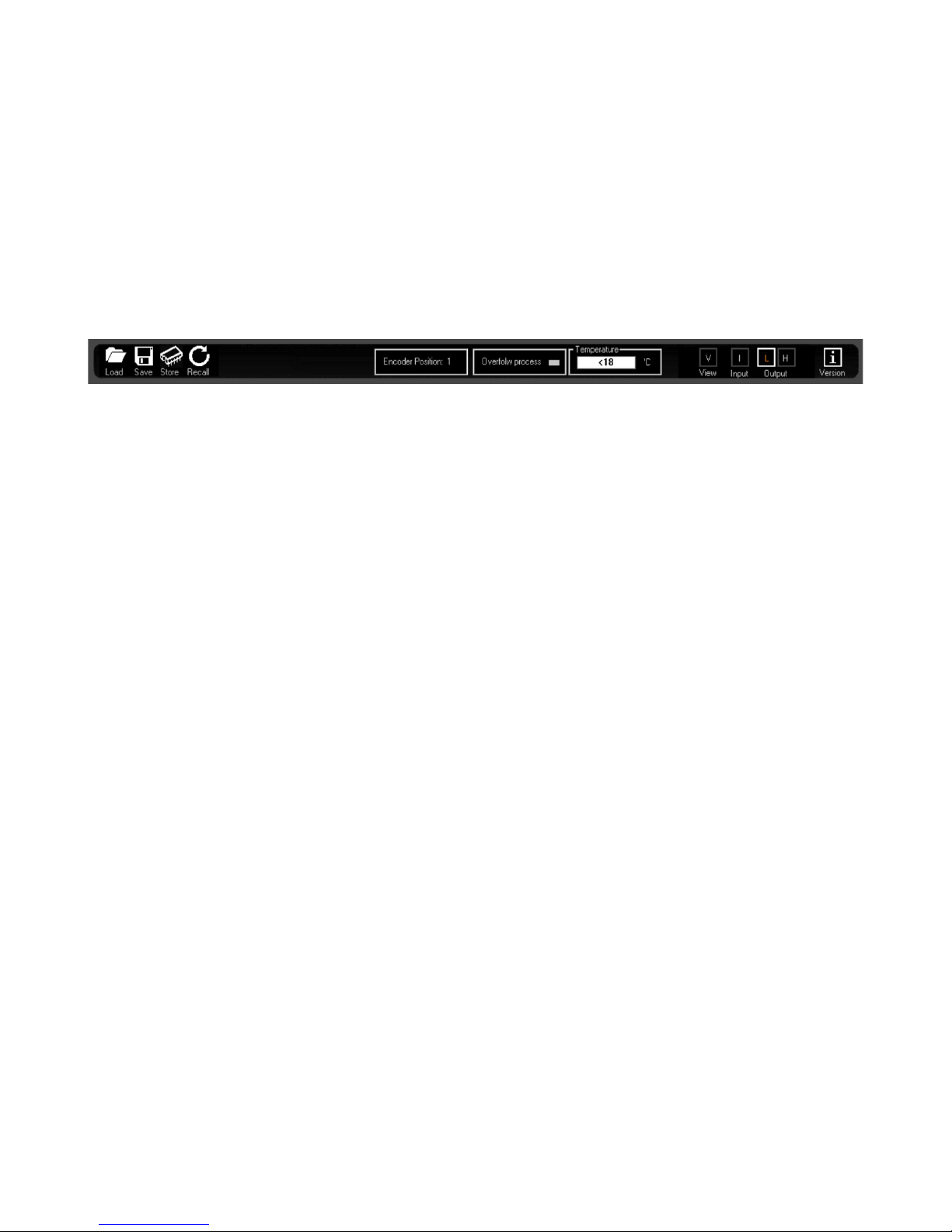
On the ALL Editing Windows, the Top Bar is fixed and shows e er the se eral a ailable “tools'' useful
for the User to manage the Editing Job so as to sa e it on Pc or within the unit.
TOOL BAR
NOTE ON PRESET STRUCTURE ON PDA500PF: Before to proceed with the description of the functions
related to the se eral icons and buttons on the tool bar, need to describe which is the presets'
structure adopted for the PDA500PF. We did start from the idea that the presets ha e to in ol e ONLY
the Input path parameters, and not to in ol e the Output Sections. This basically because we
considered that the Plate, once set the proper configuration for the specific cabinet, has to ha e the
output parameters, as Xo er and delay, or Phase set, fixed, being those parameters strictly related t
the cabinet itself and its set up, and not instead used for creating different “sounding styles”, which
are left to the user in terms of Input parameters set up. On the base of this principle, we did manage
the preset structure so to gi e the possibility to Sa e on / load from Pc or store into / recall from the
PDA500PF up to 8 Input configurations, and set the single Output configuration in a dedicated area of
the PDA500PF internal memory.
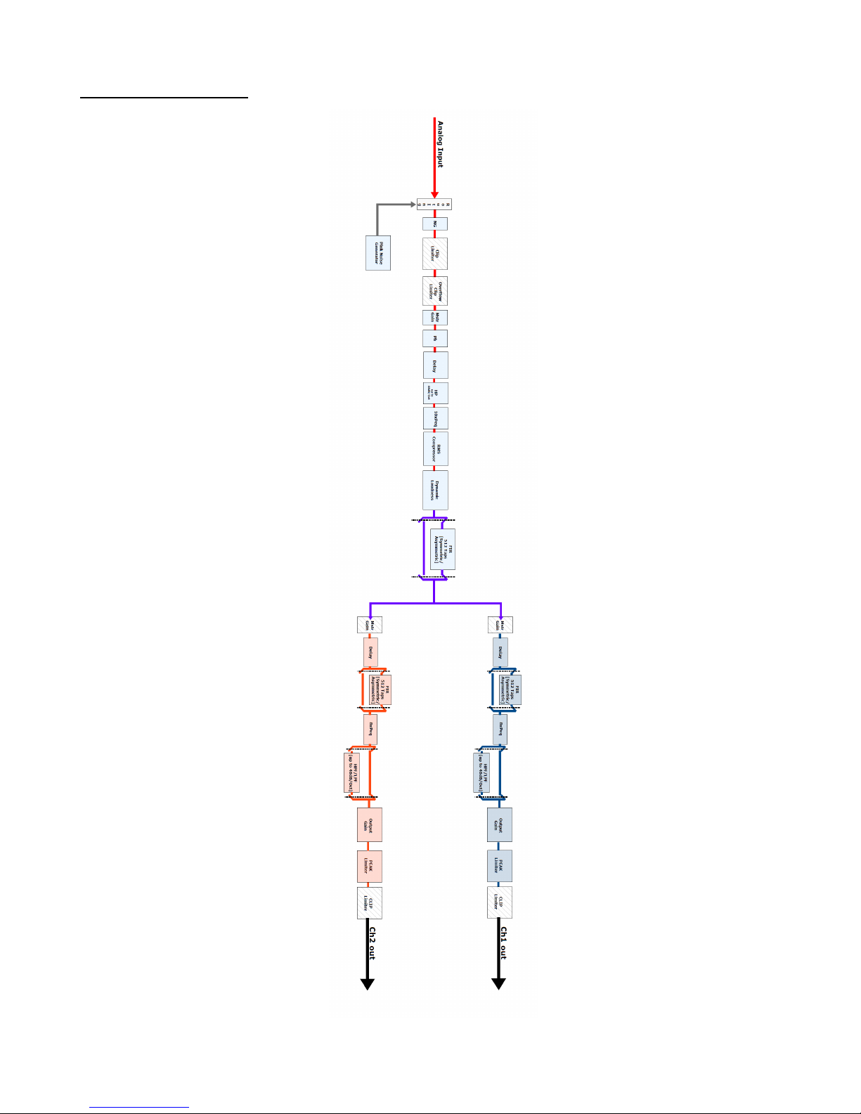
To be more clear, let define the following as the INPUT PARAMETERS, which are the ONLY ONES sa ed
on / Loaded from Pc and Stored into / recalled from the internal memory of the PDA500PF when a
preset is created:
–Input Gain
–Input Mute
–Input Phase
–Input NoiseGate (Bypass,Thr,Rel,Atk)
–Input Delay
–Input RMS Compressor (Bypass, Thr, Ratio, nee, Rel, Atk, Makeup)
–Input Dynamic Filter
–Input HP Filter
–Input 10 PEQ (Type, Freq,Q,Gain,Bypass)
–Enable/Disable FIR Phase correction
–Name Preset
Particularly, the one abo e are the ONLY parameters sa ed on Pc and loaded from Pc.
All other parameters, included the ones related to the Outputs configurations, are stored ONLY withi
the PDA500PF memory.

The internal memory of the PDA500PF is organized as follow:
----------------------------------
Input preset 1
----------------------------------
Input preset 2
----------------------------------
Input preset 3
----------------------------------
Input preset 4
----------------------------------
Input preset 5
----------------------------------
Input preset 6
----------------------------------
Input preset 7
----------------------------------
Input preset 8
----------------------------------
Current input buffer
----------------------------------
Fixed output parameters
----------------------
System ariables
----------------------------------
When the PDA500PF is turned on, the MCU is taking some action
1. Read the Encoder position on the Plate, so to load as current preset, the one selected by the
encoder itself, which will be actually the combination of the Input Preset selected and set it on
the Current input buffer (temporary), then load the Output configuration resident within the
Fixed output parameters location.
2. Set the all System ariables.
After that, the PDA500PF is working without Pc connected, performing the selected preset.
If the Pc will be connected for an Editing Session, the Pc, connection time, will read the Current input
buffer, the Fixed output parameters area and the System ariables are, and show the current
Input/Output configuration on the Editing windows. If a parameter not belonging to the pre iously
defined INPUT PARAMETERS list, is modified, which most likely then is related to the Inputs
configuration or to System ariables, then the new alue of the parameter is sa ed into the “Fixed”
memory area. If a parameter belonging to the INPUT PARAMETERS list, is modified, then the new
alue of the parameter is sa ed into the “Buffer” memory area.
When finally the user is deciding to sa e on Pc or to Store into a location of the {DA500PF the new
preset, the content of the “Buffer” area is sa ed on Pc or Stored into the selected location of the 8
a ailable on the PDA500PF. The “Fixed” area is untouched by the Sa ing and storing actions.

On the base of the note abo e, Load/Sa e. Store and Recall icons allow the following...
Load: Load a pre iously sa ed Input Configuration from a defined Pc directory. The configuration
loaded will be the one edited with its parameters set on the input editing windows. The configuration
loaded is containing only the Input parameters
Save: Sa e the current Input Configuration (the all parameters set within the Input Window) into a
defined Pc directory. The sa ed configuration is containing the Input parameters.
Store: Sa e the current Input Configuration (the all parameters set within the Input Editing Window)
into one of 8 a ailable locations within the PDA500PF. The sa ed configuration is containing the ALL
parameters set in the Input Editing Window and can be recalled also from the unit's front panel.
Recall: Load a pre iously sa ed Input Configuration from one of 8 a ailable locations within the
PDA500PF. The configuration loaded will be the one edited with its parameters set on the Input
editing window.
The stored Preset within the unit are re-callable on the PDA500PF, by the external available 8
positions absolute encoder.
E coder Positio : this frame is indicating the current position of the Absolute Encoder located on the
PDA500PF Plate.
Overflow Process: this Led turn ON if an O erflow is occurring within the DSP processes and the
O erflow Clip Limiter become therefore Acti e. [see IMPRTANT NOTE later]
Temperature: in this frame is displayed the current Temperature of the Power Stages. If the
temperature is exceeding the 80Deg Celsius, the the DSP set Outputs (feeding the power Stages) are
MUTED.
V: button allowing to access the GAINS and SYNOPTIC image Main Editing Page
I: buttons allowing to access the INPUT CHANNEL Editing Pages
L/H: buttons allowing to access the OUTPUT CHANNELS Editing Pages
i: info button, gi ing information about the Firmware and Pc Sw ersion.

GAIN a d SYNOPTIC WINDOW
This Window is guesting a synoptic image of the se eral processes a ailable on the Input and Output
paths of the PDA500PF, so as a series of “frames” for the selection/setting of particular processes.
The Main Input of the PDA500PF, is a Bala ced A alog one, coming from the the Front Panel XLR
connector.
Noise Ge erator frame: In alternati e to the Analog Input, a Noise Generator can be sent to the DSP
processes and to the PDA500PF outputs.
- Noise Ge erator: when enabled, the Analog Input is replaced by the output of the internal nose
Generator. The internal Noise Generator can generate White or Pink Noise and its Le el can be
controlled by the related Slider ranging from -40dBu up to 0dBu.

Clip limiter frame: Here is possible to set a Clip limiter on outputs able to limit the output itself up to
-6dBu from its maximum le el. This Clip limiter can be useful, after the Peak Limiter on the output
paths, to dramatically cut with infinite attack time, the output signal, there where APEC is used for
processing signals going to external Class D amplifiers, in example, without internal Limiting circuitry.
FIR phase correctio frame: here are a ailable the controls for the use of a 512 Taps FIR located on
the Input path, which has been added mainly for being used for PHASE CORRECTION purposes, there
where used together with the “Wizard” process embedded in the PDA500PF Sw (see NOTE A), able to
control a measurement process bringing to the calculation of the necessary coefficients for the phase
linearization of a 2 way system.
Ne ertheless, the FIR on the input paths can also work with coefficients loaded by external files and
generated by Third Party Sw able to generate FIR coefficients. In this case, the FIR turn to be a up to
512 Taps standard FIR, which can be loaded with any sort of coefficients for getting any sort of result
(PEQ, Min Phase, Lin Phase, etc.). For the use of the external coefficients, need to generate them as
text files and import them. See the details on the NOTE B.
- Wizard: this control is launching the “Wizard” Sw for the related FIR (see NOTE A for the Wizard Sw)
- FIR Import: here external coefficients can be imported into the FIR. Pressing the “FIR Import” button,
the following window open and from the clicking on the LOAD icon, a .txt file (see NOTE B) with the
Third Party calculated coefficients can be imported.
The Amplitude and Phase responses can be seen on the graphic which will show the characteristics of
the imported filter.
- View FIR: once imported, or e en internally generated, the FIR coefficients, the response of the FIR
can be seen recalling it on graphic just pressing the 'View FIR” button.
- Byp: this check box is useful for making the loaded Fir Acti e or not. When not acti e, checked box,
the FIR is simply transparent on the related input path. The Byp can therefore be used as powerful
tool for A/B comparison between the system responses using or not the FIR.

Dy amic Filter frame: the Dynamic filter is in facts a Dynamic Loudness which is a Dynamic Filtering
boosting automatically the Input le el on Low and high Frequencies on the base of the Input Le el
RMS alue. Particularly the boost is applied with a couple of Bell filters with different small Qs [pretty
wide BW] centered at 50Hz and 12kHz. At these 2 frequencies the boosts ha e different amount: the
boost on Lows at his maximum reaches +7dBV when the input signal is -28dBV from its max and the
boost on Highs reaches its maximum boost with +3dBV. The amount of boost on the Lows and highs
can anyway be tuned with sliders controlling in percentage the boosts amounts independently. The
following table gi es the details about the Boost amounts per Low and High frequencies in relation
with the Input Signal le el.
The table has to be read as follow...
The 2dBu, 0dBV, represent the Input Le el at the one the boost on both Lows and Highs stops,
maintaining a constant alue up to the Max input le el of 12dBV. The le el of -16dBu, which is -18dBV,
is the Input Le el at the one the Boost for both lows and highs reaches its maximum and remain
constant for the all lower input signals.
ADC Headroom [12dB] frame: checking the ADC Headroom box, an internal process is made acti e,
which is allowing to ha e onto the PDA500PF A/D con erters a +12dB headroom. This means that the
MAX output le el of the Amplifier is reached yet when the input signal is at -12dBu from the Max
accepted le el accepted by the A/D con erters. Each increase of the Input le el in front of the A/D
from the -12dBu, is contained by an internal Clip Limiting process. This feature is allowing to get then
the Max power deli ered by the Amp when still 12dB of Headroom are a ailable on the Inputs, so
allowing to ha e already the Max Power performances and a oid Clips there where the input signal is
Exceeding the -12dBu from the max acceptance.

IMPORTANT NOTE: the PDA500PF has in internal Algorithm controlling the le el coming from the
Processes including gain ariations as, Filtering Gains or Simply Le el Gains, there where the Gain
coming from the processes themsel es can be a positi e one. In this case, it is possible, gi en an input
le el close the the max a ailable, to ha e internal processes o erflow. The PDA500PF inner Clip
limiting Algorithm is detecting the potential or already occurring o erflows and is containing them up
to a 12dB Headroom, with a process “distortion free” based on le el reduction tabled coefficients.
[Note that this algorithm is different from the one used for the 12dB Headroom on the A/D converters,
being the one here described “containing” digital potential overflo s coming from the internal DSP
processes]. When o erflow o er 12dB occurring on the internal processes, the Algorithm is containing
them with a no distortion free process, which progressi ely is increasing the distortion le el as more
as the o erflow containment is exceeding the +12dBu. The result of this “transparent to the user
process”, is a NOT CLIPPED output signal e en with large excess of gaining internal processes and Input
le els close to the max accepted by the unit. The process is acti e ONLY in case of O erflow occurring;
when the signal is not exceeding with the sum of the Input le el and the processes gain, the unit's
dynamic, then the process is not acti e.
I put Meters: the input meters show the Input le els from -36dBu up to +12dBu. The Limit Led is
indicating if Acti e the RMS Compressors. The Clip Led is indicating if the Clip limiter Algorithm
described here abo e is acti e on the Input path.
Output Meters: the output meters show the output le els from -36dBu up to +12dBu. The Limit Led is
indicating if the Peak Limiter. The Clip Led is indicating if the Clip limiter Algorithm described here
abo e is acti e on the Output path.
Sliders: the sliders control the Input/Output le els ranging from -12dBu up to +12dBu.
Phase (Polarity): control for in erting the signal polarity (180Deg.)
Overflow Process: this led is turning ON when an internal o erflow is occurring at digital processes
le el.
Sy optic Image: The Synoptic Image is showing in clear way the a ailable processes on Input and
Output paths, so as gi es the possibility to directly MUTE/UNMUTE input and any output, just clicking
on the related loudspeaker icons. Clicking on any block of the Input path or Output path, the user is
immediately brought to the editing window of the related Input or Output channel.

INPUT WINDOW
All the processes a ailable on the Input Paths can be edited within the Input Windows.
Eq Flat a d Bypass Co trols: the EQ Flat control is allowing to flat in one shot the 10 bands Parametric
Eq. The Bypass control, instead, is allowing to temporarily Bypass the Eq, without resetting the current
setting.
EQ Filters: within this frame, the all 10 filters of the PEQ can be defined in terms of type, gain, Freq, Q
- Filters type: on top of the Slider and the box showing the gain le el, there is a button that once
pressed is opening a wide list of filters type which can be selected, for each filter of the parametric Eq.
The a ailable filters are Bell (constant Q), Hi/Low Shelvi g Q (Symmetrical with ariable Q), Lp/Hp Q
(12dB/Oct second order, ariable Q) and Notch.
- Gai : the filter types which can gain, ha e the gain controlled by a slider ranging from -15dBu up to
+15dBu.
- Freq: here can be inserted the Center, Cutting Frequency of the selected filter, ranging from 20Hz up
to 20kHz.
- Q: there where usable, the Q can be set with a range depending from the selected filter.
- Byp: any filter of the 12 of the Parametric Eq, can be singularly bypassed, so to ha e the possibility to
a quick A/B comparison between the signal when acti e or not the filter currently in editing phase.

Cursor: clicking on this control, cursors will appear on the graphic showing the amplitude response of
the parametric Eq, for the setting of the filters' gain by mouse action.
View All: this control is opening a window showing the full Eq setting on each Input or Output or
combination of them.
Mag a d Phase: it is possible to decide if showing on the Window's graphic the Magnitude response
of the Parametric Eq setting (Mag selected) or the Phase response (Phase selected).
Delay: the Input delay can be set here. The delay (in ms or meter) can be set using the button
up/down “Adj” with step 1ms or “Fine” with step 10.4us (max input delay = 480ms =163.5meter)
High Pass Filter: a Hp filter up to 48dB/Oct of Classic types is a ailable there where the APEC sw is
used for a cabinet working with a separate SUB.
RMS Compressor: the PDA500PF is implementing a powerful RMS compressor on Inputs and Outputs,
which compression coefficient is calculated on the base of tabled alues gi ing a compression step of
0.1dB.
- Bypass: Compressor Acti e or not (Note that the all parameters here below are not accessible when
the Compressor is set in Bypass)
- Threshold: from -10dBu to +20dBu step 0.2dBu
- Ratio: [input:Output] from 2:1 to 32:1 step 1
- K ee: from 0% to 100% (0% hard knee, 100% soft knee
- Release-time: from 0.1sec to 3sec step 0.1 sec
- Attack-time: from 5ms to 200ms step ariable
- Make-Up: from -12dB to +12dB step 0.1dB
Noise Gate: a noise gate is a ailable
- Bypass: Noise Gate Acti e or not
- Threshold: from --80dBu to -50dBu step 5dBu
- Release-time: from 10ms to 1sec step ariable
- Attack-time: from 1ms to 1sec step ariable

OUTPUT WINDOW
All the processes a ailable on the Output Paths can be edited within the Output Windows.
Eq Flat a d Bypass Co trols: the EQ Flat control is allowing to flat in one shot the 8 bands Parametric
Eq. The Bypass control, instead, is allowing to temporarily Bypass the Eq, without resetting the current
setting.
EQ Filters: within this frame, the all 8 filters of the PEQ can be defined in terms of type, gain, Freq, Q
- Filters type: on top of the Slider and the box showing the gain le el, there is a button that once
pressed is opening a wide list of filters type which can be selected, for each filter of the parametric Eq.
The a ailable filters are Bell (constant Q), Hi/Low Shelvi g Q (Symmetrical with ariable Q), Lp/Hp Q
(12dB/Oct second order, ariable Q) and Notch.
- Gai : the filter types which can gain, ha e the gain controlled by a slider ranging from -15dBu up to
+15dBu.
- Freq: here can be inserted the Center, Cutting Frequency of the selected filter, ranging from 20Hz up
to 20kHz.
- Q: there where usable, the Q can be set with a range depending from the selected filter.
- Byp: any filter of the 8 of the Parametric Eq, can be singularly bypassed, so to ha e the possibility to
a quick A/B comparison between the signal when acti e or not the filter currently in editing phase.

Cursor: clicking on this control, cursors will appear on the graphic showing the amplitude response of
the parametric Eq, for the setting of the filters' gain by mouse action.
View All: this control is opening a window showing the full Eq setting on each Input or Output or
combination of them.
Mag a d Phase: it is possible to decide if showing on the Window's graphic the Magnitude response
of the Parametric Eq setting (Mag selected) or the Phase response (Phase selected).
Delay: the Input delay can be set here. The delay (in ms or meter) can be set using the button
up/down “Adj” with step 1ms or “Fine” with step 20.8us (max input delay = 680ms =231meter)
RMS Compressor: the PDA500PF is implementing a powerful RMS compressor on Inputs and Outputs,
which compression coefficient is calculated on the base of tabled alues gi ing a compression step of
0.1dB.
- Bypass: Compressor Acti e or not (Note that the all parameters here below are not accessible when
the Compressor is set in Bypass)
- Threshold: from -10dBu to +20dBu step 0.2dBu
- Ratio: [input:Output] from 2:1 to 32:1 step 1
- K ee: from 0% to 100% (0% hard knee, 100% soft knee
- Release-time: from 0.1sec to 3sec step 0.1 sec
- Attack-time: from 5ms to 200ms step ariable
- Make-Up: from -12dB to +12dB step 0.1dB
Peak Limiter: a Peak Limiter for Loudspeaker protection is a ailable
- Bypass: Peak limiter Acti e or not
- Threshold: from --10dBu to 20dBu step 0.2dBu
- Release-time: from 100ms to 5sec step ariable
Table of contents
Popular Amplifier manuals by other brands

Bose
Bose SoundTouch SA-5 Start here

Altec Lansing
Altec Lansing 9444A POWER AMPLIFIER manual

Electro-Voice
Electro-Voice 7300A Owner's Operation and service manual

Plinius
Plinius SA-100 Series instruction manual

Elan
Elan D1200 Installation manual and user's guide

YORKVILLE
YORKVILLE Coliseum CA12 Service schematics