Thermionic Culture The Earlybird 4 User manual

CULTURE
THERMIONIC
TheEarlybird 4
valve microphone pre-amplifier
OPERATING MANUAL

©Thermionic Culture Ltd., July 2014 1
WARNING
For your personal safety, please read this operating manual and
warning thoroughly before using the equipment.
This unit must be installed in such a manner that operator access
to the mains plug is maintained. Where the product is to be rack
mounted, this may be achieved by having access to the
disconnection device for the whole rack.
To reduce the risk of electric shock, it is essential that the unit is
disconnected from the mains supply before removing the cover.
Please also note that the power supply capacitors within this unit
can remain charged even after the mains supply has been
disconnected. It is essential that these capacitors are discharged
after the mains supply has been disconnected and the covers
have been removed.
In the event that this unit has been dropped or has suffered an
impact, an electrical safety test must be carried out before
reconnection to the mains supply.
This equipment is not intended for use in explosion hazard
environments. It must be used and stored in studio conditions,
such that the ambient relative humidity does not exceed 80%, nor
is the temperature to be allowed to drop to a level, which would
cause dew point to be reached.
Please ensure that adequate ventilation is provided and that the
ventilation slots are not obstructed. When rack mounting this
equipment, a fan may be required to provide sufficient airflow.

©Thermionic Culture Ltd., July 2014 2
CONTENTS
Section Page
1 Introduction 3
2 Controls 4
2.1 Gain 4
2.2 Bass filter 4
2.3 Pad 4
2.4 Z
2.5 +48V 4
2.6 Phase reverse 4
2.7 Output trim 4
3 Metering 6
4 Operational suggestions 7
5 Specification 8

©Thermionic Culture Ltd., July 2014 3
1Introduction
The Earlybird 4 is a four-channel mic-amp employing a
balanced push-pull all valve circuit, which as far as we know,
is unique in this application. The use of this type of circuit
gives seriously low noise, plenty of headroom and means a
very natural interpretation of whatever sound the microphone
is picking up, whether the mic is valve, dynamic or FET.
The Earlybird 4 mic amps are improved versions of the
Earlybird 1 and 2 series. They have improved Sowter input
and output transformers and traditional point-to-point hand
wiring by experts, eliminating the (slight) performance
degradation occurring when using circuit boards. The phase
shift is therefore very small and the distortion so low as to be
almost unmeasurable, especially in the mid range at the
most used gain settings. There is a natural warmth to the
sound but there is no compromising the frequency response,
and of course no solid state in the audio chain so no
“hardening” of the sound.
The Earlybird 4 should be considered as probably the
best microphone amplifier ever made.
“It’s like connecting a wire with gain to a microphone”.

©Thermionic Culture Ltd., July 2014 4
2Controls
2.1 Gain
The gain is varied in steps of 5dB from 40dB to 60dB,
as stated on the front panel, though actual max gain is
2 – 4 dB more with 300 ohm input .impedance and a
low impedance source.
2.2 Bass filter
The response is flat when this switch is fully anti-clockwise.
It acts at 50 & 100Hz. The effect becomes more drastic as
the frequency drops.
2.3 Pad
Cuts down the input level by 20dB. Use with Z set to
1200Ωfor cleanest results.
2.4 Z
Switches input impedance between 300Ωand 1200 Ω.
This is for matching microphones (see 4).
2.5 +48V
Applies phantom power to Mic In sockets. Switch on
only when an FET mic is used. NEVER use if inputs
may be unbalanced or with ribbon microphones..
2.6 Phase reverse
These switches will invert the phase of the signal.in
the corresponding channel, when in.
2.7 Output trim
These controls are reverse linear attenuators,
operating after the electronics. The full output of the

©Thermionic Culture Ltd., July 2014 5
electronics is available when the controls are set to
maximum. These controls are designed to be both
‘fine’ level controls and to reduce the output to feed
-10dBV systems.

©Thermionic Culture Ltd., July 2014 6
3Metering
The meters are of a VU type, but they have a compressed
scale above 0VU. They measure the actual output of the
electronics, less 2dB, not necessarily the actual output as
they precede the Output Trim controls. They will only
measure the actual output when the Output Trim is set to the
‘M’ position (with a load impedance of 10kΩ).
NOTE:- 0 VU is set to the original British standard of +8 dBm
rather than the usual US standard or +4 dBm.

©Thermionic Culture Ltd., July 2014 7
4 Operational Suggestions
For most microphones 300Ωwill give best results. 1200Ωis
recommended by Neumann for FET mics (though we like the
sound of the U67 on 300Ω). 1200Ωis good for SM58s. For
high level inputs, eg. kick drum, use the Pad to reduce level.
With Pad in the input, Z will be 2kΩ.
Keep Output Level controls near maximum for cleanest
results, low and increase Gain control if a bit of distortion is
what you want. The electronics have plenty of headroom for
most purposes, so don’t worry too much if the needle of the
meter hits the end stop.
High gain settings make the sound more ‘gritty’ than lower
ones, which are very smooth.

©Thermionic Culture Ltd., July 2014 8
5 Specification
Included are the figures for noise, distortion and EQ. They
are all measured with the Earlybird set up for 44dB mic gain /
0 dB line gain and a 10kΩload.
Input impedance
With Pad in:
300Ωor 1200Ω, switchable,
balanced
2kΩ
Output impedance
(a) Output level control at max
(b) Output level control at min
55Ωbalanced
500Ωbalanced
Maximum gain 62-64dB
Maximum output level (MOL) +34dBm
Distortion (THD) @
1kHz/100Hz, unweighted, at 40dB
gain
0.0035% / 0.008%
Frequency response
±0.5dB at 40dB gain setting
>10Hz to<35kHz
Gain settings (dB)
Mic
40, 45, 50, 55 & 60dB
High pass filter (Hz) 50 & 100Hz
Output trim -17dB to +2dB reverse linear
attenuator
Input and output connectors 4 x 3 pin XLRs, wired balanced
Valve complement 4x12AX7LPS/ECC803/7025
4x6189/ECC82
Pilot light bulb 12V/3W
Fuses 115V: T1 A
230V: T500mA
Typical frequency response
40dB 45dB 50dB 55dB 60dB
LF (Hz) 3 3 4 5 9
HF (kHz) 58 50 36 23 15
Less than 1dB variation between the ‘LF’ and ‘HF’
frequencies shown above.

©Thermionic Culture Ltd., July 2014 9
Typical values for Distortion, Noise and Phase shift
40dB 50dB 60dB
THD (%) @ 100Hz *
to 10kHz 0.003 0.015 0.03
Noise (dB ref. MOL) -117 -113 -104
Phase shift (°) @
100Hz
1kHz
10kHz
20kHz
0 (0%)
1 (0.3%)
14 (3.9%)
28 (7.8%)
0 (0%)
1.4
(0.4%)
17 (4.7)
35 (10%)
3 (0.8%)
2 (0.6%)
31 (8.6%
62 (17%)

Thermionic Culture Ltd., Harlow, Essex, UK
©Thermionic Culture Ltd., July 2014. Printed in UK.
Table of contents
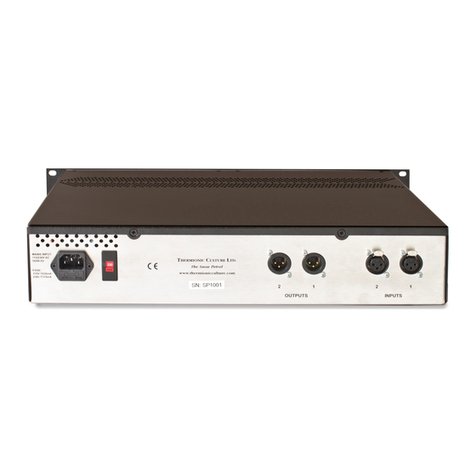
Other Thermionic Culture Amplifier manuals
Popular Amplifier manuals by other brands
Pioneer
Pioneer VSA-AX10 operating instructions
Audiotec Fischer
Audiotec Fischer Match M 2FX installation instructions
AfterBurner
AfterBurner 420 Installation & operation instructions

Sony
Sony TA-A790N Service manual
Lab.gruppen
Lab.gruppen LAB 2002 user manual

VocoPro
VocoPro FEATHER AMP FA-500 owner's manual
