Removable line cord
Refer to Figure 1 and Figure 7 or Figure 8 when
installing the power suppl wiring for the removable line
cord. If our kit has a DPDT toggle switch then use
Figure 7. If our kit has a DPST rocker switch the use
Figure 8.
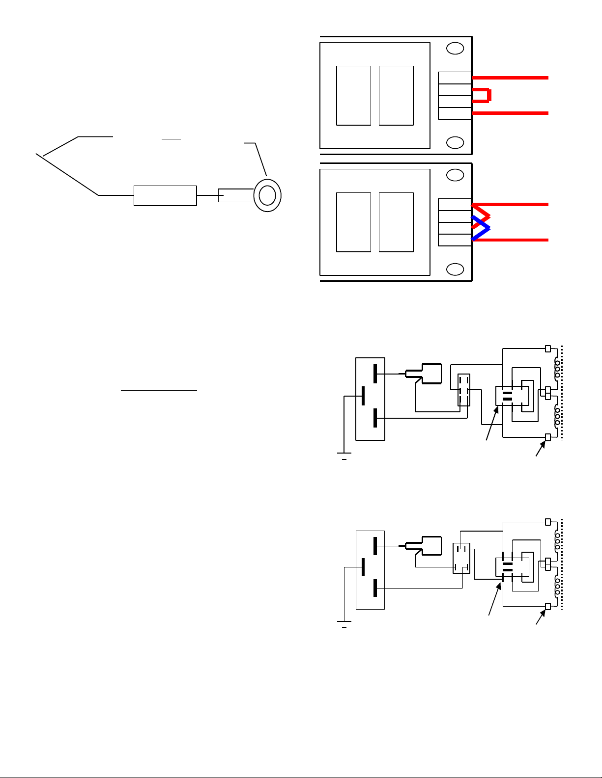
Two rocker switches are included in the kit that has
rocker switches. The illuminated switch with the colored
lens is used for the power and the one without the lens is
used for the sum switch. Note that the rocker switch has
two pairs of contacts; one pair is closer together than the
other. Use the pair that is cose together for the wires that
go to the transformer.
Use high voltage (thick insulation) #22 hookup wire to
make the connections between the power entr
connector, the power switch on the front panel and the
power selector switch on the rear panel and the fuse
holder. Install heat shrink tubing over all junctions. Use
wire colors as shown in .
Make sure to securel install the grounding wire between
the ground terminal on the power entr connector and
the chassis. Solder a 3” piece of green/ ellow hookup
wire to one of the solder lugs provided. Solder the free
end of the wire to the ground terminal and secure the
solder lug to the chassis with one of the 6/32 screws
holding the rear panel.
Set the voltage selector switch to the proper voltage
before proceeding.
Attached AND Removable line cord
Install a 1A fuse in the fuse holder.
We will now test the power supply. Plug the cord in and
turn on the power switch. The two LED indicators on the
power suppl and the front panel LED indicator should all
light.
UNPLUG the power cord before proceeding.
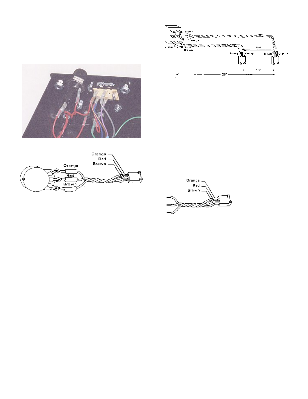
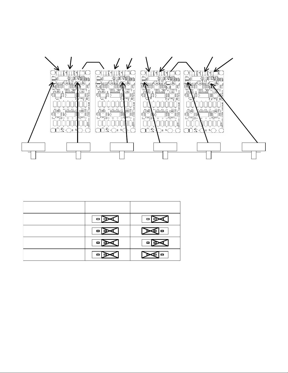
Now the RCA connectors are to be connected to the
circuit boards. Note that the circuit boards have groups of
3 holes marked P6,P7,P8 on the XM9 and P5,P6,P7 on
the XM16. The twisted pairs from the RCA connectors
connect to these locations according to the tables below.
There are four tables (1..4), one for each configuration of
the crossover network. Be sure to solder the red wire to
the small hole in the center of the group, and the brown
ground wire to one of the 3 larger holes in the group. The
boards will have to be removed in order to do the
soldering. On the 3-wa units there also is a set of two
jumper wires between the boards. Make the jumper
connection b running a red wire between the center holes
of the locations indicated and a brown wire between the
grounds at the locations indicated. For example, for the
XM16L-3KK there is a jumper wire between P5 of the left
board and P7 of the left center board, etc.
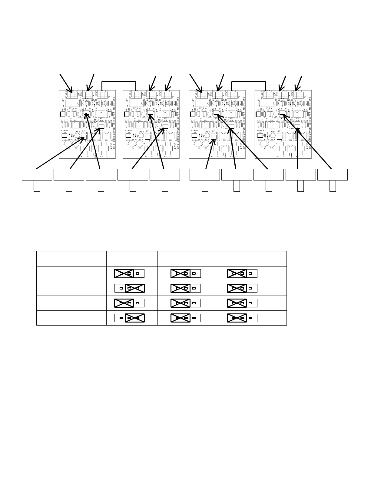
There are several trimmer potentiometers on the
crossover boards. The should all be set to the center
position.
Connect the 2 (4) power cables from the power suppl to
the crossover boards. On the XM9 the cables are plugged
into connectors marked P2. On the XM16 the power
cables are plugged into the connectors marked P1.
The sum-mode cable is hooked to two 3-pin molex
connectors according to the table 5.
The level and damping controls are hooked up
according to table 6.
There are several jumpers on each board. These
jumpers serve to enable the off board level and damping
controls. Near each connector that was used in table 6
there is a 3 position male connector, labeled 1J2 or 3J4 or
5J6. A jumper block should be placed on each of these
connectors. If a cable was connected to the P connector,
then the jumper should be placed over the RIGHT two
pins. If no cable was connected the jumper should be
placed over the LEFT two pins.
Make sure all the jumpers have been installed.
Install the control knobs onto the level and damping
controls. The knobs should be installed so that the arrow
indicator on the knob is at the 12 o'clock position when the
control is centered. The position of the knob when it is
turned full clockwise is thus left-right mirrored from when
it is turned full counterclockwise. When installed in this
s mmetric fashion, the calibration on the front panel will be
correct.
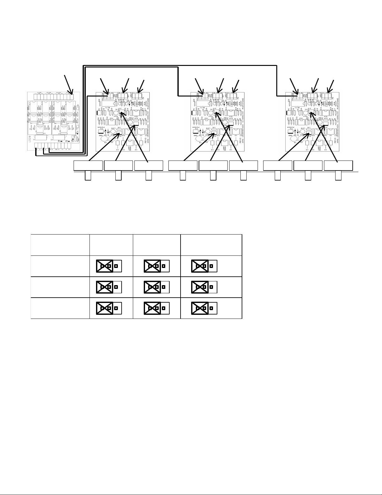
3-Channel Unit
The 3-channel unit use 3 crossover boards and one LD28
summer board. There is no sum switch. The LD28 board
is installed to the left of the 3 crossover boards, as seen
from the front of the unit. The power suppl cable to the
LD28 is the same as for a crossover board. The output
marked OUT4+ of the LD28 Should be connected to the
connector marked “sum” on the rear panel. The 3 inputs
marked IN1, IN2 and IN3 should be connected to the low
pass outputs of the crossover boards. Use black/red
twisted wire pairs for these connections; the red wire being
the signal and the black wire the ground. Note that the
low-pass outputs of the crossover boards now have two
connections each: to the output connectors and to the
summer board.
Frequency Modules
Install the frequenc modules for the proper frequencies.
For the two wa units all frequenc modules have the
same value. On the 3 wa units, install the frequenc
modules with the LOWER frequenc into the Left and
Right-center boards, and the frequenc modules with the
HIGHER frequenc into the Left-Center and Right boards.
The Top Cover of the unit can be installed now or at a
later time. Fasten the top with 4 6/32 x 1/4" screws. In
case it is difficult to insert the screws, loosen the screws
that hold on the front and rear panels and tr again. Now
fasten all screws well.
The assembl is now completed.
© 2000 Marchand Electronics Inc. PO Box 473, Webster, NY, 14580 www.marchandelec.com (716) 872 0980 FAX: (716) 872 1960 4