manuals.online logo
Brands
  1. Home
  2. •
  3. Brands
  4. •
  5. Monacor
  6. •
  7. Crossover
  8. •
  9. Monacor DN-2618 User manual

Monacor DN-2618 User manual

ELECTRONICS FOR SPECIALISTS ELECTRONICS FOR SPECIALISTS ELECTRONICS FOR SPECIALISTS ELECTRONICS FOR SPECIALISTS ELECTRONICS FOR SPECIALISTS ELECTRONICS
DN-2618
Bestell-Nr. • Order No. 12.2260
MONACOR INTERNATIONAL GmbH & Co. KG • Zum Falsch 36 • 28307 Bremen • Germany
Copyright©by MONACOR INTERNATIONAL. All rights reserved.
High
8 Ω
BM
L 1
0m68
L 2
0m27
H
C 1
3µ
150 V
MKT
R1
4Ω7
10 W
I N P U T
C 2
10µ
150 V
MKT
Rx
1 × Bass / Mid 4 Ω or 8 Ω or
2 × Bass / Mid 8 Ω
BM
L 1
BM 8 ΩH
IN
Input
H
R 1
C 2
C 1
Rx L 2
BM
BM H
BM
DN-2618
MONACOR INTERNATIONAL
ZUM FALSCH 36 · 28307 BREMEN
GERMANY
MAX. 350 W/8 Ω
1 × Bass / Mid 4 Ω or 8 Ω or
2 × Bass / Mid 8 Ω
➂
➀
➁
20 50 100 200 500 1k 2 k 5 k 10 k 20 kHz
40
30
20
10
dB
A-1726.99.02.07.2019
2-Way Crossover Network
for Speaker Systems
These instructions are intended for non-
professionals with basic knowledge in DIY
speaker building. Please read the instruc-
tions carefully prior to operation and keep
them for later reference.
1 Applications
This crossover network is specially designed
for setting up a 2-way speaker system with a
power capability of up to 350W.
2 Important Notes
The crossover network corresponds to all rel-
evant directives of the EU and is therefore
marked with .
•
The crossover network is suitable for indoor
use only. Protect it against dripping water
and splash water, high air humidity and heat
(admissible ambient temperature range:
0–40°C).
•
For cleaning only use a dry, soft brush; never
use water or chemicals.
•
No guarantee claims for the crossover net-
work and no liability for any resulting per-
sonal damage or material damage will be
accepted if the crossover network is used for
other purposes than originally intended, it it
is not correctly connected, if it is overloaded,
or if it is not repaired in an expert way.
If the crossover network is to be put
out of operation definitively, take it to
a local recycling plant for a disposal
which is not harmful to the environ-
ment.
3 Connection
1) Connect the bass/midrange speaker (4Ω or
8Ω impedance depending on the desired
crossover frequency, ☞specifications) to
the pins “BM+” and “BM−” (fig.3). Two
8Ω speakers may be connected in parallel.
2) Connect the tweeter (8Ω impedance) to the
pins “H+” and “H−”. The correct connec-
tion of the positive and negative contacts
depends on the speakers used and their
arrangement within the speaker system. To
find the ideal connection for your speaker
configuration, test the options with a sound
check.
3) The pins “IN” are used as a signal input.
4 Specifications
Input power:. . . . . . . . . .350 W max.
Output impedance:. . . . .8Ω (bass also 4 Ω)
Crossover frequency
Low pass at 4/8Ω: . . . .1700Hz/3000Hz
High pass:. . . . . . . . . . .3000 Hz
Slope
Low pass: . . . . . . . . . . . 6 dB/octave
High pass: . . . . . . . . . . 18dB/octave
Dimensions: . . . . . . . . . .125 × 32 × 110 mm
Weight: . . . . . . . . . . . . .410g
Subject to technical modification.
2-Wege-Frequenzweiche
fürLautsprecherboxen
Diese Anleitung richtet sich an Selbstbau-
Amateure von Lautsprecherboxen mit
entsprechenden Grundkenntnissen. Bitte
lesen Sie die Anleitung vor dem Betrieb
gründlich durch und heben Sie sie für ein
späteres Nachlesen auf.
1 Verwendungsmöglichkeiten
Diese Frequenzweiche ist speziell für den Auf-
bau einer 2-Wege-Lautsprecherbox mit einer
Belastbarkeit von bis zu 350W konzipiert.
2 Wichtige Hinweise
für den Gebrauch
Die Frequenzweiche entspricht allen relevan-
ten Richtlinien der EU und trägt deshalb das
-Zeichen.
•
Die Frequenzweiche ist nur zur Verwendung
im Innenbereich geeignet. Schützen Sie sie
vor Tropf- und Spritzwasser, hoher Luftfeuch-
tigkeit und Hitze (zulässiger Einsatztempera-
turbereich 0– 40°C).
•
Verwenden Sie zum Reinigen nur einen tro-
ckenen, weichen Pinsel, auf keinen Fall Was-
ser oder Chemikalien.
•
Wird die Frequenzweiche zweckentfremdet,
falsch angeschlossen, überlastet oder nicht
fachgerecht repariert, kann keine Haftung
für daraus resultierende Sach- oder Per-
sonenschäden und keine Garantie für die
Weiche übernommen werden.
Soll die Frequenzweiche endgültig
aus dem Betrieb genommen werden,
übergeben Sie sie zur umweltgerech-
ten Entsorgung einem örtlichen Recy-
clingbetrieb.
3 Anschluss
1) Den Bass-/Mitteltonlautsprecher (Impedanz
4Ω oder 8 Ω entsprechend der gewünsch-
ten Trennfrequenz, ☞Techn. Daten) an
die Stifte „BM+“ und „BM−“ anschließen
(Abb.3). Es können auch zwei 8-Ω-Laut-
sprecher parallel angeschlossen werden.
2) Den Hochtöner (Impedanz 8Ω) an die Stifte
„H+“ und „H−“ anschließen. Der richtige
Anschluss der Plus- und Minuskontakte
hängt von den eingesetzten Lautsprechern
sowie von ihrer Anordnung in der Box ab
und muss durch Probieren ermittelt werden.
3) Die Stifte „IN“ dienen als Signaleingang.
4 Technische Daten
Eingangsbelastbarkeit: . .max. 350 W
Ausgangsimpedanz: . . . .8 Ω (Bass auch 4Ω)
Trennfrequenz
Tiefpass bei 4/8 Ω: . . . .1700 Hz/3000Hz
Hochpass:. . . . . . . . . . .3000 Hz
Flankensteilheit
Tiefpass: . . . . . . . . . . . . 6 dB/Oktave
Hochpass:. . . . . . . . . . .18 dB/Oktave
Abmessungen: . . . . . . . .125 × 32 × 110 mm
Gewicht:. . . . . . . . . . . . .410 g
Änderungen vorbehalten.
DeutschEnglish
ELECTRONICS FOR SPECIALISTS ELECTRONICS FOR SPECIALISTS ELECTRONICS FOR SPECIALISTS ELECTRONICS FOR SPECIALISTS ELECTRONICS FOR SPECIALISTS ELECTRONICS
MONACOR INTERNATIONAL GmbH & Co. KG • Zum Falsch 36 • 28307 Bremen • Germany
Copyright©by MONACOR INTERNATIONAL. All rights reserved. A-1726.99.02.07.2019
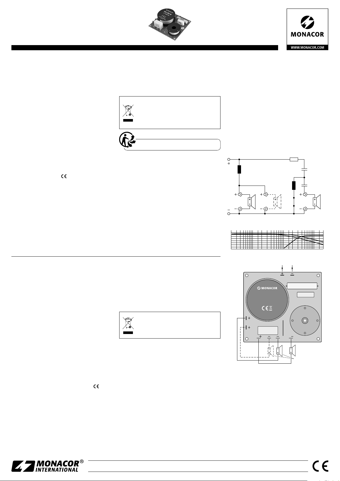
High
8 Ω
BM
L 1
0m68
L 2
0m27
H
C 1
3µ
150 V
MKT
R1
4Ω7
10 W
I N P U T
C 2
10µ
150 V
MKT
Rx
1 × Bass / Mid 4 Ω or 8 Ω or
2 × Bass / Mid 8 Ω
BM
L 1
BM 8 ΩH
IN
Input
H
R 1
C 2
C 1
Rx L 2
BM
BM H
BM
DN-2618
MONACOR INTERNATIONAL
ZUM FALSCH 36 · 28307 BREMEN
GERMANY
MAX. 350 W/8 Ω
1 × Bass / Mid 4 Ω or 8 Ω or
2 × Bass / Mid 8 Ω
➂
➀
➁
20 50 100 200 500 1k 2 k 5 k 10 k 20 kHz
40
30
20
10
dB
Filtro crossover a 2 vie
per casse acustiche
Queste istruzioni sono rivolte alle persone
che desiderano costruirsi da sole delle
casse acustiche e che dispongono delle
relative conoscenza base. Vi preghiamo di
leggere attentamente le presenti istruzioni
prima della messa in funzione e di conser-
varle per un uso futuro.
1 Possibilità d’impiego
Questo crossover è stato realizzato special-
mente per la costruzione di una cassa acustica
a 2vie con potenza massima fino a 350W.
2 Avvertenze importanti
per l’uso
Il crossover è conforme a tutte le direttive rile-
vanti dell’UE e pertanto porta la sigla .
•
Il crossover è previsto solo per l’uso all’in-
terno di locali. Proteggerlo dall’acqua goc-
ciolante e dagli spruzzi d’acqua, da alta
umidità dell’aria e dal calore (temperatura
d’impiego ammessa fra 0 e 40°C).
•
Per la pulizia usare solo un pennello morbido,
asciutto; non impiegare in nessun caso acqua
o prodotti chimici.
•
Nel caso d’uso improprio, di collegamenti
sbagliati, di sovraccarico o di riparazione
non a regola d’arte del filtro crossover, non
si assume nessuna responsabilità per even-
tuali danni consequenziali a persone o a
cose e non si assume nessuna garanzia per
il crossover.
Se si desidera eliminare il crossover
definitivamente, consegnarlo per lo
smaltimento a un’istituzione locale
per il riciclaggio.
3 Connessione
1) Collegare il woofer/midrange (impedenza
4Ω o 8 Ω a seconda della frequenza di taglio
richiesta, ☞Dati tecnici) con i pin “BM+“
e “BM−” (fig. 3). Si possono collegare in
parallelo anche due altoparlanti di 8Ω.
2) Collegare il tweeter (impedenza 8Ω) con i
pin “H+” e “H−”. La corretta connessione
dei contatti positivo e negativo dipende
dagli altoparlanti impiegati e dallo loro di-
sposizione nella cassa e deve essere stabilita
facendo delle prove.
3) I pin “IN” servono come ingresso dei segnali.
4 Dati tecnici
Potenza max. d’ingresso:.350 W max.
Impedenza d’uscita: . . . .8 Ω
(bassi anche 4Ω)
Frequenza di taglio
Passabasso con 4/8Ω:. .1700Hz/3000Hz
Passaalto: . . . . . . . . . . .3000 Hz
Pendenza
Passabasso:. . . . . . . . . . 6dB/ottava
Passaalto: . . . . . . . . . . .18 dB/ottava
Dimensioni:. . . . . . . . . . .125 × 32 × 110mm
Peso:. . . . . . . . . . . . . . . .410 g
Con riserva di modifiche tecniche.
DN-2618
Référence num.• Codice 12.2260
Filtre de fréquences 2 voies
pour enceintes
Cette notice s’adresse aux non-profession-
nels avec des connaissances de base dans
la conception d’enceintes. Veuillez lire la
présente notice avec attention avant le
fonctionnement et conservez-la pour pou-
voir vous y reporter ultérieurement.
1 Possibilités d’utilisation
Ce filtre de fréquences est spécialement conçu
pour le montage d’une enceinte 2 voies avec
une puissance de 350W max.
2 Conseils importants
d’utilisation
Le filtre de fréquences répond à toutes les di-
rectives nécessaires de l’Union européenne et
porte donc le symbole .
•
Le filtre de fréquences n’est conçu que pour
une utilisation en intérieur. Protégez-le des
éclaboussures, de tout type de projections
d’eau, d’une humidité élevée de l’air et de
la chaleur (température ambiante admissible
0– 40°C).
•
Pour le nettoyage, utilisez uniquement une
brosse sèche, douce, en aucun cas de pro-
duits chimiques ou d’eau.
•
Nous déclinons toute responsabilité en cas
de dommages matériels ou corporels résul-
tants si le filtre de fréquences est utilisé dans
un but autre que celui pour lequel il a été
conçu, s’il n’est pas correctement branché,
s’il y a surcharge ou s’il n’est pas réparé par
une personne habilitée; en outre, la garantie
deviendrait caduque.
Lorsque le filtre de fréquences est
définitivement retiré du service, vous
devez le déposer dans une usine de
recyclage adaptée pour contribuer à
son élimination non polluante.
CARTONS ET EMBALLAGE
PAPIER À TRIER
3 Branchement
1) Reliez le haut-parleur de grave/médium (im-
pédance 4Ω ou 8 Ω selon la fréquence de
coupure voulue, ☞caractéristiques techn.)
aux pins «BM+» et «BM−» (schéma 3).
Deux haut-parleurs 8Ω peuvent également
être branchés en parallèle.
2) Reliez le haut-parleur d’aigu (impédance 8Ω)
aux pins «H+» et «H−». Le branchement
correct des contacts plus et moins dépend
des haut-parleurs utilisés et de leur place-
ment dans l’enceinte. Pour le branchement
idéal de la configuration, faites un test audio.
3) Les pins «IN» servent comme entrée de signal.
4 Caractéristiques techniques
Puissance d’entrée: . . . .350W max.
Impédance de sortie: . . .8 Ω (grave aussi 4Ω)
Fréquence de coupure
Passe-bas avec 4/8Ω:. .1700Hz/3000Hz
Passe-haut : . . . . . . . . .3000Hz
Pente
Passe-bas : . . . . . . . . . . 6dB/octave
Passe-haut : . . . . . . . . .18dB/octave
Dimensions: . . . . . . . . . .125 × 32 × 110 mm
Poids:. . . . . . . . . . . . . . .410 g
Tout droit de modification réservé.
FrançaisItaliano

This manual suits for next models

1

Other Monacor Crossover manuals

Monacor DN-10 User manual

Monacor

Monacor DN-10 User manual

Monacor MCX-200/SW User manual

Monacor

Monacor MCX-200/SW User manual

Monacor DN-2618P User manual

Monacor

Monacor DN-2618P User manual

Monacor DN-20 User manual

Monacor

Monacor DN-20 User manual

Monacor CARPOWER CDN-2X User manual

Monacor

Monacor CARPOWER CDN-2X User manual

Monacor DN-20 User manual

Monacor

Monacor DN-20 User manual

Monacor DN-1218PAX User manual

Monacor

Monacor DN-1218PAX User manual

Popular Crossover manuals by other brands

Australion monitor AMIS23X Installation and operation manual

Australion monitor

Australion monitor AMIS23X Installation and operation manual

Ashly SC88 product manual

Ashly

Ashly SC88 product manual

Boss Audio Systems BX-55 user manual

Boss Audio Systems

Boss Audio Systems BX-55 user manual

Legacy LXR-3A user manual

Legacy

Legacy LXR-3A user manual

Alto MAXIDRIVE3.4 PC user manual

Alto

Alto MAXIDRIVE3.4 PC user manual

Behringer SUPER-X PRO CX2310 user manual

Behringer

Behringer SUPER-X PRO CX2310 user manual

Omnitronic XO-230 user manual

Omnitronic

Omnitronic XO-230 user manual

Crunch CRXR Operator's guide

Crunch

Crunch CRXR Operator's guide

Electro-Voice EX23 owner's manual

Electro-Voice

Electro-Voice EX23 owner's manual

dbx 223/223XL Operation manual

dbx

dbx 223/223XL Operation manual

Pyle PPCX3 instruction manual

Pyle

Pyle PPCX3 instruction manual

HELIX DXP-6 Competition instruction manual

HELIX

HELIX DXP-6 Competition instruction manual

Rane MX 23 Operator's manual

Rane

Rane MX 23 Operator's manual

Kenwood KEC-302 instruction manual

Kenwood

Kenwood KEC-302 instruction manual

Sony XES-X1 owner's manual

Sony

Sony XES-X1 owner's manual

Peavey PSX Specifications

Peavey

Peavey PSX Specifications

Audio Research PC-3 instruction manual

Audio Research

Audio Research PC-3 instruction manual

Rane AC 22S Operator's manual

Rane

Rane AC 22S Operator's manual

manuals.online logo
manuals.online logoBrands
  • About & Mission
  • Contact us
  • Privacy Policy
  • Terms and Conditions

Copyright 2025 Manuals.Online. All Rights Reserved.