ENG
7
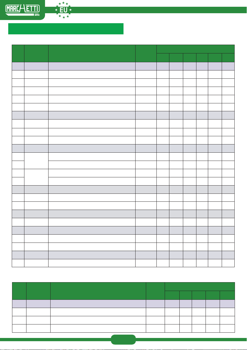
Cod. Component Elements Weight
Kg
CONFIGURATIONS
A1 A2 A3 A4 A5 B6 B7 B8
20580 EXTRACTABLE BASE
1 20551 Wheel-bearing section for extr. Base S120 12,70 1 1 1 1 1 1 1 1
2 20550 Wheel-bearing section for extr. Base S120 12,60 1 1 1 1 1 1 1 1
3 20554 Base brace - 180 6,00 2 2 2 2 2 2 2 2
4 20318 Extractable adjustable foot 3,50 4 4 4 4 4 4 4 4
5 30523 Handgrip screw M14x50 0,14 4 4 4 4 4 4 4 4
20584 TOWER
10 20556 Bearing frame - 120 9,50 2 4 6 8 10 12 14 16
11 20562 Connecting brace - 180 3,50 2 4 6 8 10 12 14 16
12 20566 Diagonal bracing - 180 1,20 4 8 12 16 20 24 28 32
21077 WORK PLATFORM - STEEL
24
21086
Platform w/trapdoor - 180x51 13,74 1 1 1 2 2 2 3 3
26 Long toeboard - 180 3,55 2 2 2 4 4 4 6 6
25 21087 Platform w/out trapdoor - 180x51 13,64 1 1 1 2 2 2 3 3
27 Short toeboard - 180 1,59 2 2 2 4 4 4 6 6
20749 COMPLETE GUARDRAILS
17 20631 Long guardrail - 180 5,10 2 2 2 2 2 2 2 2
18 20784 Short guardrail - 120 2,30 2 2 2 2 2 2 2 2
GUARDRAIL BARS
28 20600 Guardrail bar - 180 1,95 0 0 0 2 2 2 4 4
20753 COMPLETE STABILIZERS
19 20765 Stabilizers - 35 9,80 0 0 4 4 4 4 4 4
20 31383 Stabilizers coupler for round tube- 35 1,00 0 0 8 8 8 8 8 8
21557 COMPLETE STABILIZERS
19 21557 Telescopic Stabilizer - 35 6,25 0 0 4 4 4 4 4 4
Table of elements composing the congurations
IDENTIFICATION SYSTEM 120X180
For congurations with H=0,90 m terminal riser A1T-A2T-A3T-A4T-A5T-B6T-B7T, add the following elements:
Cod. Component Elements Weight
Kg
CONFIGURATIONS
A1T A2T A3T A4T A5T B6T B7T
20586 TOWER
21 20557 Bearing frame - 120 5,80 2 2 2 2 2 2 2
11 20562 Connecting brace - 180 3,50 2 2 2 2 2 2 2
22 20567 Terminal diagonal bracing - 180 1,10 4 4 4 4 4 4 4