User Instructions
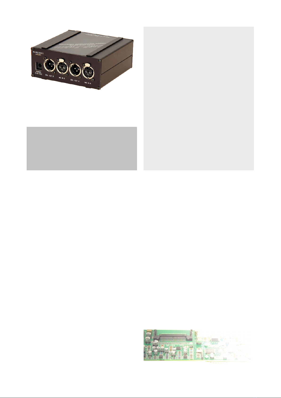
Attach the PSU to the DC supply socket. Polarity should be center pin (+). The DC input is polarity protected.
Activate SMF-5 by switching POWER on.
Connect the microphones to the XLR input sockets.
Switch on 48 V phantom power, if desired.
Make a choice of balanced XLR or unbalanced output (through the front panel mini-tele socket).
Select basic gain by the gain switches and add additional gain by the potentiometers.
Connect a headphone to the front panel socket and adjust audio level by the phones gain potentiometer.
Note 1:
Do not short-circuit the XLR output signal pins 2 or 3 to GROUND pin 1. The outputs are transformerless.
Note 2:
Do not connect unbalanced microphones while 48V phantom power is active. This may destroy the microphone.
Dynamic, balanced microphones will not be damaged by 48 V phantom power.
Technical Data SMF-5mkIII
Frequency range 5 - 40 kHz (-3 dB)
10 - 20 kHz (+-0.5 dB)
THD @ 30 dB gain <0,006% @ 1 kHz, +12 dBu
Max. gain 70 dB (64 dB for unbal. out)
Channel crosstalk <-88 dB @ 1 kHz
Equiv. input ref. noise <-131 dBu with lowZ in
Input sockets XLR-3F
Mic input impedance 1 K ohms
Mic input level max. -6 dBu
Output sockets XLR-3M and mini-tele 3.5 mm
Audio output impedance 2 x 22 ohms balanced
Audio output level max. +24 dBu (XLR)
max. +18 dBu (mini-tele)
Phantom power 48 V+-1 V, max 5 mA
Power supply External supply 10 - 35 VDC,
2.1 mm socket
Size W x H x D approx. 140 x 60 x 136 mm,
excl. sockets and knobs
Weight approx. 900 grams
Carrying case PortaBrace original, optional
Specications are subject to change without notice.
Box includes:
1x SMF-5mkIII
1x Power supply
1x User Instructions (English)
SMF-5mkIII Nov 2010
Copyright MARENIUS ELEKTRONIKUTVECKLING AB, Sweden
MARENIUS
ELEKTRONIKUTVECKLING AB
P O Box 5086
SE-42605 V Frolunda, Sweden
Te l +46-31-691610
Fax +46-31-693188
- Designers of Electronics -
Visit www.marenius.com for information about other MARENIUS products.
Balanced sockets wiring:
1 ground/shield
2 hot
3 cold


