1. Specifications
Power: Non-powered -no power supply required
Size:4.0"W x 2.25"Dx 1.0"H
Weight:6 oz
MTBF >100,000 hours
Altitude Tolerance Any
Temperature Tolerance Operating: 32° to 158° F (0° to 70° C);
Storage: -4° to 185° F (-20° to 85° C)
Humidity Tolerance Up to 95% non-condensing
Interface: RS232
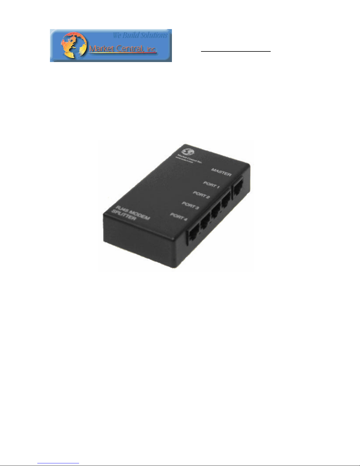
Connectors
(1) single style RJ45 socket connector -(MASTER)
(1) quad style RJ45 connector -(PORT 1 -4)
Leads Supported
Pins 3, 4, 5, 7, and 8 connected straight thru between the MASTER and PORT 1 -4.
Pins 1, 2, and 6 “diode ORed” from PORT 1 -4 to the MASTER port.
.
2. Introduction/Operation
The RJ45 Modem Splitter is designed to permit multiple terminals to share a single modem. The modem
splitter is a passive, non-powered devices and are transparent to data formats, rates & protocols. Data
received from the line and output by the modem as RS232 voltage levels is simultaneously transmitted thru
the modem splitter to all of the terminal devices attached to that modem splitter Likewise, RS232 control
signals output by the modem are simultaneously transmitted to all of the attached terminal devices.
RS232 data output by the attached terminal devices is logically “OR’d” by the modem splitter and then
transmitted to the modem. Because of this, only one terminal device may send data to the corresponding
modem at a time. If more than one terminal device connected to that modem splitter sends data at the same
time, the electrical signals will be combined causing the data going to the modem to be corrupted. The
RS232 control signals output by the terminal devices are likewise logically “OR’d” so that if a control
signal is active on any of the terminal devices (RTS for example), the modem splitter will assert that signal
to the modem. If that signal is not asserted by any of the attached terminal devices, then the modem splitter
will pass thru this inactive state signal to the modem.
This design approach allows the RS232 messages output by the modem to be broadcast to all of the
attached terminal devices, and for the appropriate terminal device to respond to each message. The message
protocol typically includes an identifier so that the terminal devices are able to identify which messages are
addressed to them. When the addressed terminal device is ready to reply, if it uses hardware handshaking it
will assert the RTS signal which the modem splitter transmits via it’s logical “OR”circuitry to the modem.
The modem will respond by asserting the CTS signal which is then broadcast via the modem splitter back
to all the terminal devices including the one that is asserting the RTS signal, thus allowing flow control
regardless of which terminal device is active.