martens TV125M User manual

Operating Manual
Universal Isolating Amplifier
TV125M / ST125M
Save for later reference.
www.ghm-messtechnik.de
Companies / Brands of GHM
English

GHM Messtechnik GmbH –Standort Martens
Kiebitzhörn 18 ● 22885 Barsbüttel ● Germany
Phone +49-40-670 73-0 ● Fax -288
www.ghm-messtechnik.de ● info@martens-elektronik.de
2
Table of contents Page
1Intended use (areas of application) ...........................................................................3
1.1 Safety signs and symbols 4
1.2 Safety instructions 4
1.3 Product liability and warranty 5
1.4 Standards and directives 5
2Product description.....................................................................................................6
2.1 Scope of delivery 6
2.2 Functional principle 6
2.3 Block circuit diagram 7
2.4 Type plate 7
2.5 PowerRail mounting rail bus 8
3Assembly and installation ..........................................................................................9
3.1 Mechanical assembly 9
3.2 Electrical installation 9
3.3 Connection diagram 10
4Controls, functional description, output, transmitter feed....................................10
4.1 Controls, functional description 10
4.2 Status LED 12
4.3 Output 12
4.4 Transmitter feed (only ST125) 12
5Commissioning, maintenance and service.............................................................13
5.1 Commissioning 13
5.2 Maintenance 13
5.3 Service 13
6Technical data............................................................................................................14
6.1 Mechanical design / dimensions 18
7Order key....................................................................................................................19
8Device transport and storage...................................................................................20
9Return to manufacturer.............................................................................................20
10 Disposal......................................................................................................................20
11 Imprint.........................................................................................................................20
12 EC Certificate of conformity.....................................................................................21

GHM Messtechnik GmbH –Standort Martens
Kiebitzhörn 18 ● 22885 Barsbüttel ● Germany
Phone +49-40-670 73-0 ● Fax -288
www.ghm-messtechnik.de ● info@martens-elektronik.de
3
1 Intended use (areas of application)
Refer to the chapter 'Product description' for detailed specifications for
the area of application.
The operational safety of the device is only assured when used as in-
tended in accordance with the specifications in the operating manual.
Intervention beyond the actions described in the operating manual may only be car-
ried out by personnel authorised by the manufacturer for safety and warranty rea-
sons. Conversions or modifications made on one's own authority are expressly pro-
hibited.
Application-specific dangers can emanate from this device when used improperly or
not as intended.
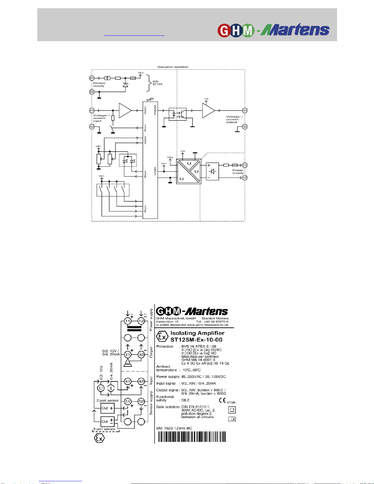
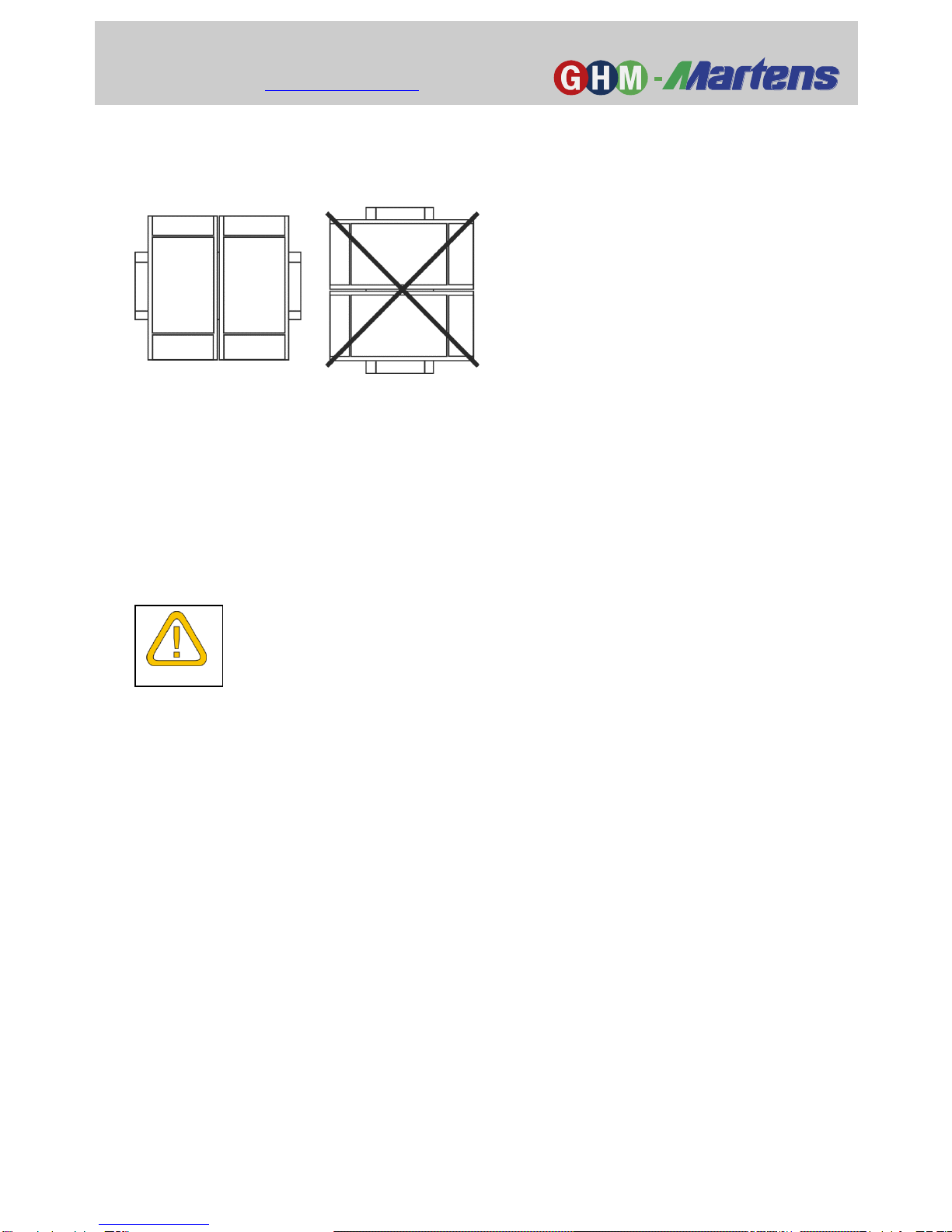
Only device versions TV125M-Ex, TV125MP-Ex, ST125M-Ex and
ST125MP-Ex are permitted for use as operating equipment for connec-
tion of intrinsically safe sensors, installed in Zones 0 or 1 and/or 20
or 21.
All safety-relevant characteristic data must be observed in this connec-
tion.
The approval for all intrinsically safe operating equipment is voided if it
has been previously connected to non-intrinsically safe power circuit,
because compliance with the safety-relevant characteristic data cannot
be 100% guaranteed there.
Therefore, a safety test must be conducted by the manufacturer before
later use as an intrinsically safe operating device.
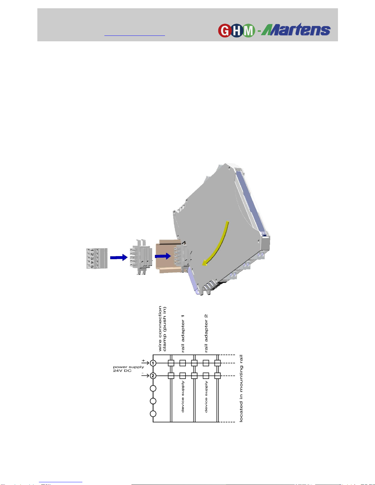
The device TV125MP-00, ST125MP-00 and all other versions of the
series TV****-Ex and ST****-Ex can be installed in the explosion-prone
Zone 2 under the following conditions:
- Installation in a clean environment in a conductive, earthed housing
(switch cabinet) with a minimum protection rating of IP54.
- Disconnection of connecting terminals only takes place in the
de-energised state
Basic standards: EN 60079-0 and EN 60079-15.
General safety instructions, use
This operating manual must be kept in a location such that qualified personnel can
refer to it at all times.
Any processes described in this operating manual may only be carried out by
trained, qualified personnel who are authorised by the owner and wearing protective
clothing. All rights reserved.

GHM Messtechnik GmbH –Standort Martens
Kiebitzhörn 18 ● 22885 Barsbüttel ● Germany
Phone +49-40-670 73-0 ● Fax -288
www.ghm-messtechnik.de ● info@martens-elektronik.de
4
1.1 Safety signs and symbols
Warning notices are identified in this document as described under Table 1:
1.2 Safety instructions
Read the product description before commissioning the device. Ensure
that there are no limitations for use of the product for the relevant applica-
tions.
The owner is responsible for ensuring the fault-free operation of the de-
vice. The owner is obligated to ensure compliance and to observe the re-
quired work and safety measures of the current applicable regulations for the entire
duration of use.
DANGER
Warning! This symbol warns of imminent danger which can result in
death, severe bodily injury, or severe property damage in case of
non-observance.
Attention! This symbol warns of potential dangers or harmful situa-
tions which can cause damage to the device or to the environment
in case of non-observance.
Note! This symbol indicates processes which can have a direct in-
fluence on operation or can trigger an unforeseen reaction in case of
non-observance.
DANGER

GHM Messtechnik GmbH –Standort Martens
Kiebitzhörn 18 ● 22885 Barsbüttel ● Germany
Phone +49-40-670 73-0 ● Fax -288
www.ghm-messtechnik.de ● info@martens-elektronik.de
5
1.3 Product liability and warranty
Exclusion of liability:
The contents of the operating manual have been checked to ensure conformity with
the described device. However, deviations cannot be entirely ruled out. Therefore, we
cannot assume any guarantee for complete conformity. The specifications in this
document are checked regularly and any necessary corrections are incorporated into
subsequent versions. This document is subject to technical changes. In addition, all
claims are based on the valid 'Standard Terms for the Supply of Products and Ser-
vices of the Electrical Industry'.
GHM Messtechnik cannot inspect or repair any devices without the re-
quired form having been filled in completely (see page 20).
1.4 Standards and directives
Conformity
Low Voltage Directive 2014/35/EU
Testing standard EN 61010-1: 2010
EMC Directive 2014/30/EU
Testing standard EN 61326-1: 2013
EN 61326-3-1: 2008, amended 2009
ATEX- Directive 2014/34/EU
Testing standard EN 60079-0: 2012 + A11 : 2013,
EN 60079-11: 2012,
EN 60079-15: 2011
Funktionale Sicherheit
Testing standard EN 61508-1..5: 2011
SN 29500: 2013

GHM Messtechnik GmbH –Standort Martens
Kiebitzhörn 18 ● 22885 Barsbüttel ● Germany
Phone +49-40-670 73-0 ● Fax -288
www.ghm-messtechnik.de ● info@martens-elektronik.de
6
2 Product description
Isolating amplifiers of the series TV/ST125 are suitable for potential isolation and for
conversion of unit signals - optionally in explosion-prone environments. The universal
configuration of the input, output and internal power supply by means of a wide-range
mains adapter limits the number of models to a few versions. The auxiliary voltage
supply can be optionally provided by means of a mounting rail bus connector.
The input measuring range can be switched between 0..20 mA and 4..20 mA and/or
0..10 V and 2..10 V on the front side via a DIP switch. The output measuring range
can be configured between 0..20 mA and 4..20 mA and/or 0..10 V and 2..10 V on the
front side via a DIP switch.
With the microprocessor-controlled measurement recording, undercutting and exceed-
ing of measuring ranges are detected and communicated via a two-colour status LED
on the front side. Then the output is set to a defined starting value and/or end value.
The starting value and the end value of the measuring range can be adjusted with the
two trimmers on the front side.
The device version ST125 provides an additional transmitter feed for external 2, 3-
wire sensors.
The devices can also be used in the explosion-prone Zone 2 if they are installed in a
suitable housing.
Use in systems with functional safety SIL2 is also possible.
2.1 Scope of delivery
TV125 or ST125
This operating manual
2.2 Functional principle
The input signals are amplified in the input stage, the amplitudes are limited and the
band is limited with an analogue filter of the third order. The filtered signal is digital-
ised by the analogue-digital converter of the microprocessor with a resolution of 14
bits. After scaling and a measuring range check, the signal is transmitted by means of
pulse width modulation via an optocoupler to the output stage.
The output stage converts the PWM signal to a proportional analogue value which is
then output via the output. The output current and/or output voltage are limited to a
defined starting value and/or end value. The three circuits: Input, output and auxiliary
voltage are galvanically isolated with amplified isolation.

GHM Messtechnik GmbH –Standort Martens
Kiebitzhörn 18 ● 22885 Barsbüttel ● Germany
Phone +49-40-670 73-0 ● Fax -288
www.ghm-messtechnik.de ● info@martens-elektronik.de
7
2.3 Block circuit diagram
2.4 Type plate
The type plate contains the most important identification data
Type and article designation
Technical data
Serial number / bar code
Fig. 2: Type plate
Fig. 1: Block circuit diagram

GHM Messtechnik GmbH –Standort Martens
Kiebitzhörn 18 ● 22885 Barsbüttel ● Germany
Phone +49-40-670 73-0 ● Fax -288
www.ghm-messtechnik.de ● info@martens-elektronik.de
8
2.5 PowerRail mounting rail bus
The auxiliary voltage supply of multiple devices can be combined and made easier
with a bus system in the mounting rail (TS35).
An appropriate version is available for the entire MP series or GHM rail bus devices
in a 12.5mm-wide housing.
A stackable bus adapter is connected to the mounting rail before installing the de-
vice to be supplied.
An adapter is required for each device for this purpose. Supply of the bus takes
place via a plug-in terminal strip.
The supply terminals 11 and 12 on the upper side of the device are omitted device
version TV/ST125MP provided for this purpose.

GHM Messtechnik GmbH –Standort Martens
Kiebitzhörn 18 ● 22885 Barsbüttel ● Germany
Phone +49-40-670 73-0 ● Fax -288
www.ghm-messtechnik.de ● info@martens-elektronik.de
9
DANGER
3 Assembly and installation
3.1 Mechanical assembly
Mounting rail assembly TS35, EN 60715
Gapless installation of several devices is only permitted with horizontally installed
mounting rails.
The devices can be installed in Ex Zone 2 within an earthed, conductive housing
(switch cabinet) with protection rating IP54.
3.2 Electrical installation
The device may only be installed by an electrician. Compliance with the
national and international regulations for installation of electrical and elec-
tronic systems applicable in the respective country of use is mandatory.
Voltage supply in accordance with EN 60664-1.
SIL 2 requires an EMC-adequate installation, according to EN 60204-1 (for example)
Connection of the auxiliary voltage takes place at connections 11 and 12 of the plug-in
terminal strip.
Terminals 41 and 42 are intended for the input and terminals 51 and 52 are for the
transmitter feed.
The active analogue output is provided at terminals 31 and 32.
Three are two DIP switches in the front panel for configuration of the input measuring
range and the output range. The starting value and the end value of the measur-
ing range can be adjusted with the two trimmers on the front side.

GHM Messtechnik GmbH –Standort Martens
Kiebitzhörn 18 ● 22885 Barsbüttel ● Germany
Phone +49-40-670 73-0 ● Fax -288
www.ghm-messtechnik.de ● info@martens-elektronik.de
10
Status LED
Message
Green LED illumi-
nates
Operating voltage
connected
Red and green LEDs
blink
See Table 7:
Status messages
Red LED illuminates
See Table 7:
Status messages
3.3 Connection diagram
4 Controls, functional description, output, transmitter feed
4.1 Controls, functional description
Trimmer
Adjustment
TR1
Starting value
TR2
End value
Tab. 3: Trimmer
Tab. 2: Status LED
Fig. 4: Front panel
S1: On
Off
S2: On
Off
S3: On
Off
S4: On
Off
TR1
Status LED
TR2
Fig. 3: Connection diagram
Auxiliary voltage: 85..253 VAC / 20..125 VDC
or 24 VDC +/- 15 %
Output: 0/2..10V or 0/4..20 mA
Input: 0/2..10 V or 0/4..20 mA
Transmitter feed (only ST125):

GHM Messtechnik GmbH –Standort Martens
Kiebitzhörn 18 ● 22885 Barsbüttel ● Germany
Phone +49-40-670 73-0 ● Fax -288
www.ghm-messtechnik.de ● info@martens-elektronik.de
11
DIP switches
On
Off
S1
Input configuration as voltage
input
Input configuration as current
input
S2
Output configuration as volt-
age output
Output configuration as cur-
rent output
DIP switches
On
Off
S3
Input configuration:
S1 = On: 0..10 V,
S1 = Off: 0..20 mA
Input configuration:
S1 = On: 2..10 V,
S1 = Off: 4..20 mA
S4
Output configuration:
S2 = On: 0..10 V,
S2 = Off: 0..20 mA
Output configuration:
S2 = On: 2..10 V,
S2 = Off: 4..20 mA
Configuration
S1
S2
S3
S4
Input
Output
1
Off
Off
Off
Off
4..20 mA
4..20 mA
2
Off
Off
Off
On
4..20 mA
0..20 mA
3
Off
Off
On
Off
0..20 mA
4..20 mA
4
Off
Off
On
On
0..20 mA
0..20 mA
5
Off
On
Off
Off
4..20 mA
2..10 V
6
Off
On
Off
On
4..20 mA
0..10 V
7
Off
On
On
Off
0..20 mA
2..10 V
8
Off
On
On
On
0..20 mA
0..10 V
9
On
Off
Off
Off
2..10 V
4..20 mA
10
On
Off
Off
On
2..10 V
0..20 mA
11
On
Off
On
Off
0..10 V
4..20 mA
12
On
Off
On
On
0..10 V
0..20 mA
13
On
On
Off
Off
2..10 V
2..10 V
14
On
On
Off
On
2..10 V
0..10 V
15
On
On
On
Off
0..10 V
2..10 V
16
On
On
On
On
0..10 V
0..10 V
Tab. 4: DIP switches S1 and S2
Tab. 5: DIP switches S3 and S4
Tab. 6: DIP switches, configuration

GHM Messtechnik GmbH –Standort Martens
Kiebitzhörn 18 ● 22885 Barsbüttel ● Germany
Phone +49-40-670 73-0 ● Fax -288
www.ghm-messtechnik.de ● info@martens-elektronik.de
12
4.2 Status LED
In error-free operation the front-side two-colour status LED illuminates green.
When there is an error, the status LED issues a blinking sequence consisting of a
specific number of green and red light pulses:
4.3 Output
Behaviour of the output when a range is undercut and exceeded:
4.4 Transmitter feed (only ST125)
Characteristic curve and output data (terminals 50 and 51):
Error circuit
Blinking
sequence
Cause
Green
Red
System
0
1
Electronic defect
Auxiliary
voltage
1
6
Supply voltage of the processor is too low
1
7
Auxiliary voltage < 18V
Input
2
1
Undermodulation (< -0.3mA / -0.15V or < 3.7mA / 1.85V)
2
2
Overmodulation (> 20.8mA or > 10.4V)
Output
3
1
Undermodulation (< -0.2mA / -0.1V or < 3.8mA / 1.9V)
3
2
Overmodulation (> 20.5mA or > 10.25V)
Output
Modulation range
Undermodulation
Overmodulation
0..10 V
-0,1..10.25 V linear
-0,2 V
10.5 V
2..10 V
1.9..10.25 V linear
1.8 V
10.5 V
0..20 mA
-0,2..20.5 mA linear
-0,4 mA
21 mA
4..20 mA
3.8..20.5 mA linear
3.6 mA
21 mA
Tab. 8: Modulation range
Fig. 5: Transmitter feed, characteristic curve
UN> 15 V,
IN= 20 mA,
Ri= 300 Ω,
UM= approx. 23,5 V,
IM= approx. 28 mA,
U0= 25.9 V,
I0= 92,6 mA,
P0= 598 mW
Tab. 7: Status messages

GHM Messtechnik GmbH –Standort Martens
Kiebitzhörn 18 ● 22885 Barsbüttel ● Germany
Phone +49-40-670 73-0 ● Fax -288
www.ghm-messtechnik.de ● info@martens-elektronik.de
13
5 Commissioning, maintenance and service
5.1 Commissioning
1. Ensure that the connections have been made as indicated in the connection
diagram and the auxiliary voltage is correct.
2. When connecting operating equipment from explosion-prone areas, ensure
that the device version has the appropriate approval.
3. When installing the isolating amplifier in Zone 2, the device must be installed in
a switch cabinet with protection rating IP54.
4. Make sure that the terminals are firmly screwed in.
5. After switching on the auxiliary power, check to ensure the correct configura-
tion.
Note:
After the auxiliary voltage is connected, a check of the device function takes place
according to the requirement for functional safety.
The device is ready for operation after approx. 3 seconds.
The functional test also includes a load test of the auxiliary voltage. The device is sub-
jected to the equivalent of a maximum load for a period of 2 seconds, i.e. a short-
circuited sensor supply and an output current of 21 mA at the output. The load is only
simulated, which means the sensor supply is not short-circuited internally and the out-
put current of the output is 0 mA.
5.2 Maintenance
Housing:
No cleaning or maintenance is required when operated as intended.
5.3 Service Service of the device is only possible in the factory.

GHM Messtechnik GmbH –Standort Martens
Kiebitzhörn 18 ● 22885 Barsbüttel ● Germany
Phone +49-40-670 73-0 ● Fax -288
www.ghm-messtechnik.de ● info@martens-elektronik.de
14
6 Technical data
Explosion protection
Device with intrinsically safe input, zone 0/1
(TV125M*-Ex…, ST125M*-Ex…)
Gas : II (1) G [Ex ia Ga] IIC/IIB 1)
Staub : II (1) D [Ex ia Da] IIIC 1)
1) Zertifikat BVS 16 ATEX E 126
Installation in Zone 2 : II 3 G Ex nA [ic] IIB T4 Gc 2)
2)
Manufacturer's certificate, usage conditions on page
3
Device versions without intrinsically safe input
(TV125MP-00…, ST125MP-00…)
Installation in Zone 2 : II 3 G Ex nA IIB T4 Gc 3)
(ATEX ignition protection type "n") 3)
Manufacturer's certificate, usage conditions on page
3
6.1 Parameters
6.1.1 Device without intrinsically safe input
All versions
Input terminal (Power supply):
Terminals 11(+) and 12 (-) or PowerRail connector (option **125MP)
Maximum Voltage UM AC 253 V
DC 125 V
TV125M-Ex and ST125M-Ex
Power supply U AC 85...253 V (47...63 Hz)
DC 20...125 V
Input-Power P < 4 VA
TV125MP-Ex and ST125MP-Ex
Power supply U DC 24 V (+/- 15%)
Input- Power P < 2 W
All versions
Output terminal
Terminals 31 (+) and 32 (-)
Signals output-voltage U < 30 V
Signals output-current I < 22 mA
Maximum Voltage UMAC 253 V
DC 125 V

GHM Messtechnik GmbH –Standort Martens
Kiebitzhörn 18 ● 22885 Barsbüttel ● Germany
Phone +49-40-670 73-0 ● Fax -288
www.ghm-messtechnik.de ● info@martens-elektronik.de
15
6.1.2 Device with intrinsically safe input
All versions
Input terminal (Input):
Terminals 41 (+) and 42 (-)
Output-voltage U027,6 V
Output-current I01,3 mA
Output-power P09,6 mW
(Characteristic curve trapezoidal)
Input-voltage Ui26 V
Input-current Ii113 mA
Input-power Pi 660 mW
Max. internal capacity Ci1 nF
Max. internal inductivity Li 240 nH
Max. external capacity IIB /IIIC Co667 nF
Max. external capacity IIC Co85 nF
Max. external inductivity IIB /IIIC L0200 mH
Max. external inductivity IIC L0100 mH
ST125M-Ex and ST125MP-Ex, only
Input terminal (Power supply):
Terminals 51(+) and 52(-)
Output-voltage U025,9 V
Output-current I092,6 mA
Output-power P0598 mW
(Characteristic curve trapezoidal)
Max. internal capacity Ci1 nF
Max. internal inductivity Li 240 nH
Max. external capacity IIB /IIIC Co769 nF
Max. external capacity IIC Co99 nF
Max. external inductivity IIB /IIIC L08 mH
Max. external inductivity IIC L02 mH

GHM Messtechnik GmbH –Standort Martens
Kiebitzhörn 18 ● 22885 Barsbüttel ● Germany
Phone +49-40-670 73-0 ● Fax -288
www.ghm-messtechnik.de ● info@martens-elektronik.de
16
6.1.3 Additional data for all device types
Rated voltage : 253 V AC, 125 V DC according to
EN 60079-11.
300 V AC/DC according to EN 61010-1
With overvoltage Category 2 and Degree
of Contamination 2 between all circuits.
Safe separation with amplified isolation.
Test voltage : 3 kV AC
(input / output / auxillary energy)
Working temperature : -10…60 °C
Storage temperature : -20…80 °C
Relaitve air humidity : 10 … 90 % (no condensation)
Input : Current or voltage input, switchable
Voltage Input : 0…10 V or 2…10 V, switchable
Ri = 30 kΩ. Max. overload 26 V DC.
Current Input : 0…20 mA or 4…20 mA switchable.
Ri = 51 Ω. Max. overload 113 mA.
Measuring span : adjustable ± 2 %
Zeropoint : adjustable ± 2 %
Transmitter feed (ST125, only)
Rated voltage at : > 15 V terminals 51, 52.
20 mA output current > 14 V terminals 51, 41.
Ri = 300 Ω. See characteristic curve on
page 12.
Output : Current or voltage input, switchable
Voltage Output : 0…10 V or 2…10 V switchable,
Load > 500 Ω.
Current Output : 0…20 mA or 4…20 mA switchable,
Load < 600 Ω.
Step response T90 : 40ms
Standard error : < 0,2 % of the end value
Temperature coefficient : < 0,01 % / K

GHM Messtechnik GmbH –Standort Martens
Kiebitzhörn 18 ● 22885 Barsbüttel ● Germany
Phone +49-40-670 73-0 ● Fax -288
www.ghm-messtechnik.de ● info@martens-elektronik.de
17
Housing
Material : Polyamide (PA) 6.6, UL94V-0
Colour : Light grey
Installation width : 12.5 mm
Dimensions (HxD) : 108 x 114 mm
Weight : 91 g
Protection rating : Housing IP 30, terminals IP 20 BGV A3
Connection type : Screw terminals, plug-in with wire protection,
0.2..2.5mm², AWG 24..14.
Wire stripping length: 8 mm.
Assembly : Mounting rail assembly TS35, EN 60715
Functional safety : SIL2 (parameters in accordance with EN 61508 and
SN 29500) for input types 4...20 mA or 2...10 V and
output types 4...20 mA and 2...10 V
Device type : B
HFT : 0
Error signalling : Output 0 V repective 0 mA
Reaction time : Normal function error : 40 ms
Error Normal function : 1 s (self resetting)
Device
PFH
DC
SFF
PFDavg.
1 yrs.
2 yrs.
2,5 yrs.
TV125M
7,26E-07
93,7 %
96,5 %
3,18E-03
6,36E-03
7,95E-03
TV125MP
6,95E-07
93,5 %
96,4 %
3,05E-03
6,09E-03
7,62E-03
ST125M
8,04E-07
94,4 %
96,9 %
3,52E-03
7,04E-03
8,80E-03
ST125MP
7,73E-07
94,2 %
96,7 %
3,39E-03
6,77E-03
8,47E-03

GHM Messtechnik GmbH –Standort Martens
Kiebitzhörn 18 ● 22885 Barsbüttel ● Germany
Phone +49-40-670 73-0 ● Fax -288
www.ghm-messtechnik.de ● info@martens-elektronik.de
18
6.2 Mechanical design / dimensions

GHM Messtechnik GmbH –Standort Martens
Kiebitzhörn 18 ● 22885 Barsbüttel ● Germany
Phone +49-40-670 73-0 ● Fax -288
www.ghm-messtechnik.de ● info@martens-elektronik.de
19
7 Order key
1.
2.
3.
4.
-
-
-
1.
Device version
TV125M
Wide-range mains adapter
TV125MP
Mounting rail bus connection *),
Auxiliary voltage 24 V DC +/- 15%
ST125M
Transmitter feed,
Wide-range mains adapter
ST125MP
Transmitter feed,
Mounting rail bus connection *),
Auxiliary voltage 24 V DC +/- 15%
2.
Explosion protection
00
no intrinsically safe input and no intrinsically safe trans-
mitter feed.
The devices TV125MP and ST125MP may be installed
in zone 2 according to ATEX- ignition protection type "n"
Ex
In case of installing the devices out of the ex-zone:
Input and transmitter feed are intrinsically safe in ac-
cordance to ignition protection type "ia" for zones 0 and
20.
The devices TV125MP and ST125MP may be installed
in zone 2 according to ATEX-ignition protection type "ic"
3.
Input
10
0/2..10 V / 0/4..20 mA
4.
Options
00
No options
01
Push-in terminals (plug-in)
*) see separate Power Rail information sheet

GHM Messtechnik GmbH –Standort Martens
Kiebitzhörn 18 ● 22885 Barsbüttel ● Germany
Phone +49-40-670 73-0 ● Fax -288
www.ghm-messtechnik.de ● info@martens-elektronik.de
20
8 Device transport and storage
Gentle and tension-free packaging of the housing must be ensured for transport (no
machine wrapping of the package).
The device must be stored in the environmental conditions specified in the technical
data.
9 Return to manufacturer
The legal regulations for environmental protection and our personnel re-
quire that devices which are sent back which have come into contact with
liquid are handled without risk to people or the environment.
If you send a device back to us for inspection or repair, we must request
that you strictly observe the following requirements:
On the GHM homepage under 'Downloads/forms' a return shipment form can be
downloaded.
The repair can be performed quickly and without call-back questions if:
1. a filled-in form is provided for each device,
2. the device has been cleaned and packaging which prevents damage to the device
is used, and
3. a safety data sheet for the measuring medium is affixed to the outside of the pack-
age, if the device has come into contact with a critical substance.
10 Disposal
Separation by material and recycling of device components and packaging
must take place when the device is disposed of. The valid legal regulations
and directives applicable at the time must be observed.
The device may not be disposed of with household waste. If the device
should be disposed of, return it to us with the return shipment form under section 8
filled in. We will then arrange for the proper disposal.
11 Imprint
GHM Messtechnik GmbH
Standort Martens, Kiebitzhörn 18, 22885 Barsbüttel, Germany
Managing Director: Günther Oehler
Registered office: Schloßstr. 6, 88453 Erolzheim / Germany,
Amtsgericht Ulm, Commercial Register Section B 730462
Copyright: GHM Messtechnik GmbH. All rights reserved.
Reprints, digital use of any type, and duplication may only take place with the written
authorisation of GHM Messtechnik GmbH.
DANGER
This manual suits for next models
1
Table of contents