l!
Portions of th., Jhimnev that ai-e to pass through spaces used for living quarters or storage should be
enclosed ,ar avoiti )ars..Jrral c/:),rtaci ,vitl: and pcssibie Camage to the chimnev.
C Fi il\J :''{ t:'.' ,
t\rCTE: ',f
c)'
.' ,, ',' +
- : ;'r-r -' L
i i- il'ie
l.
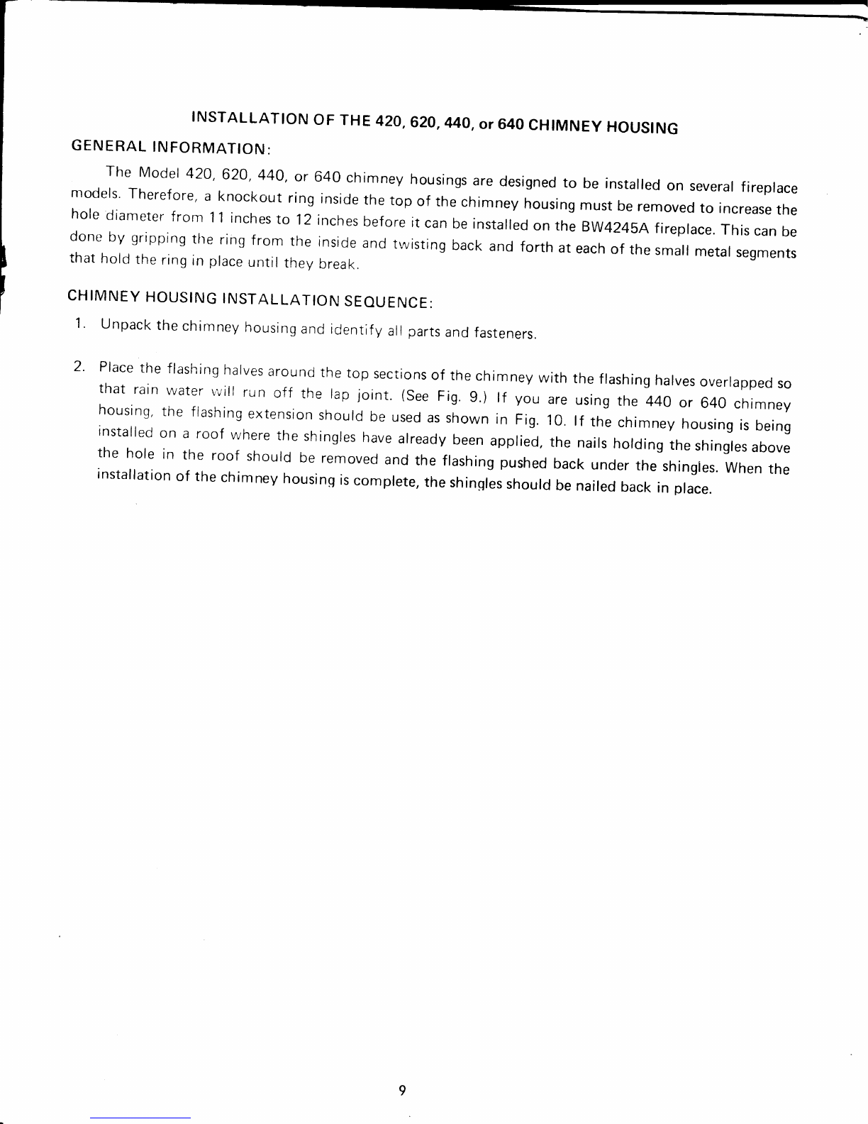
:..} TP. L LATiON SEOU EITJCE :
tir.; ch,q.i'iev is to inciucie elbo.r.s tc offset th? chirnne}', refor tr: thg sllLlo\r instaliation sr.:ciiorr
th.;:e instructions before follo'.';ing the sleo: !..eic';v.
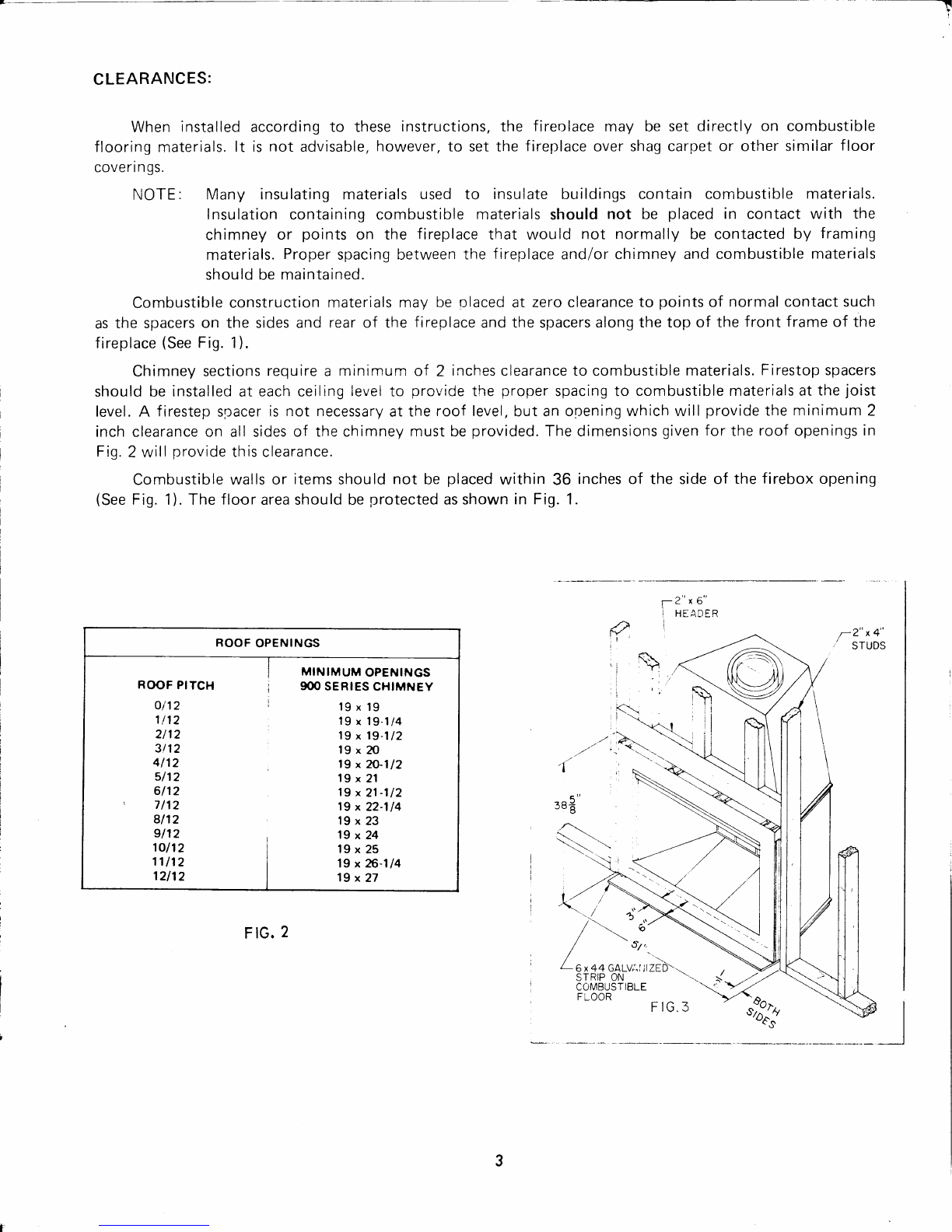
.:ut, anci franre r)penings thfor..rglratl ce irn,1S rrcj the rcof The insiiic dirrisl:si,-.rrs i,-:r'ti're i-roles
ceiiirrgs rfiust be i9 inches square. Befer to FrrUr€ 2 tor the hoie sizes to i;c usecj at the r-r:u{
of tlre proper
a l;r;ve is att ic
f iES 6;:r,.rl 7).
S== tr :-.-= :':;': t,,,,:)q rr ti:e srlect,orr
- :-' -
"a,-^ :ta=.:- :^? ae iro !inl3ss lhe si,ace
---:: ^j:a 2::''--" =:-:.? qifl.-, i:,0 ',1=
-: >t;ila.' tnto :''a ' .,a 3-i ?t Jt --. a ' '?t aaa .-at ;,rrass i'Ji,,,t-t L.;-lii :i-,i, 5,ia:) ilcr,S
i-.r: S':jf --:" S'-Cr-.'- 3: 'S:r 9C O:, i^:1-a:;ng Ci-ti'3: Of th.. firl:r ale r,V' ;o,ia-""'. it,: ti:.
': -: , J:::ar:,:'. I '? ,:l ei a i' Sterte r ::r,llid ',= : S.; :l: . ii-r lrle r',..-:{: ._: ,t-:
--e frr?1-llac? ai'rci enqaEe the snap lock3 on the top of tn,; r:eiriace.
lr;la j 1r.ra cl-. r.'r ney , ,clions by insef tino tlre male end of the flue or smallert .i,?mpte" prpe on t,)i) L1
ihe fiue starig. anri oressing dolvn r.:ntil the snap locks enqage. Next. place lhn D lle't :i:. LiLlct nr
inte:'mediate diarneter pipe directlr/ on top of the starter section and press Cow:r until the snap locks
cnqar:le Tharr, place the ir,rnale enrl 1)i thr iriiet air iluct or lrrqest diameter pipg on top of ttre inlet air
slat'tei' ano oress down r-rniii th-" sn:o ioci:s engaoe, Contirue this process, adding the chimney sections
o. IoD of e3ch other ur,t.l the chranngy 's above ine roof opening on all sides.
NOTE: T'r: ast sect on oJ :-: c-'r-1:, -sIJi:eC s-outd be either a 2' or 3'section so that the
:e as:Ope si.: o' ''r c -2aa .'. i. :ne c.l'rne\/ terminatiOn vJill telescope properly. Be sure the
S'aC Oa<: .': ;-::;:: --. SaCi- : Je Dipe SeCtiOn.
T-e c^ --e, ^-3V ce i?r-.€:.d ,...ith either a simuiated brick chlmney housing or a contemporary
'o-''la ierr-i.a: or cap Fo' scecific iaslaLiation instructions, re{er to the section of these instructions
a:tp CaC, €;9 1r9 6-i6nsr,, ter'l.llnation ithich you have chosen.
-.
' S== = I a I -:,1 l^ ..ri. o: --ie firellli(.:::;y;l.sgrii,,rl iirir
4.
5
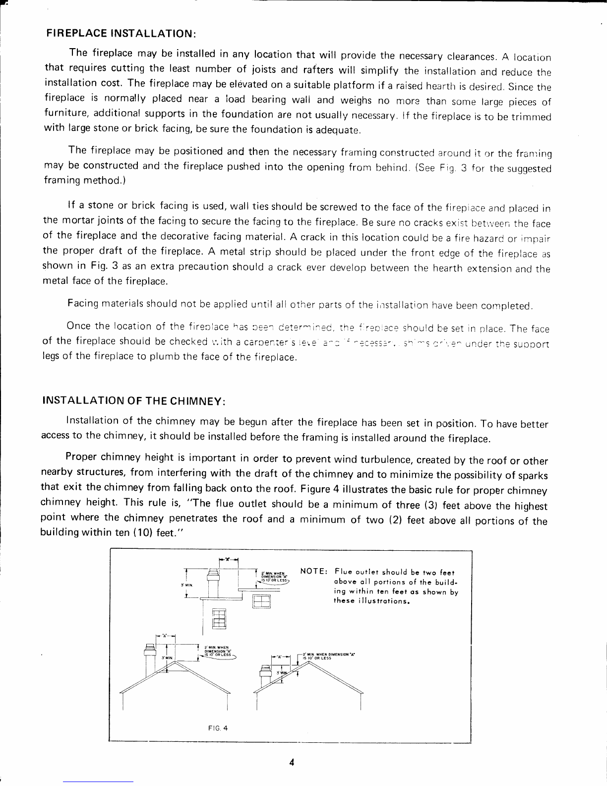
-FLOOR JOIST
,... ,,)
L FIRESTOP
SPACER
\-CHIMNE Y
SECTI ON
TNSTALLATTON OF FTRESTOP SPACER AT FLOOR ]:lyElg
FIG 6