Martin Professional CX-2 User manual

CX-2
user manual

1 focus lens
2 cover locks
3 air vent
4 safety cable holes
5 mounting bracket
6 air vents
7 AC input & main
fuse
8 DIP-switch
9 data output
10 data input
11 swivel locks
12 cooling fan
©1999, 2000 Martin Professional A/S, Denmark.
All rights reserved. No part of this manual may be
reproduced, in any form or by any means, without
permission in writing from Martin Professional A/S,
Denmark.
Printed in Denmark.
P/N 35000080, Rev. C

CX-2 user manual 3
Introduction. . . . . . . . . . . . . . . . . . . . . . . . . . . . . . . . . . . . . . . . .4
Lamp . . . . . . . . . . . . . . . . . . . . . . . . . . . . . . . . . . . . . . . . . . . . . .6
AC power connection. . . . . . . . . . . . . . . . . . . . . . . . . . . . . . . . .7
Installation. . . . . . . . . . . . . . . . . . . . . . . . . . . . . . . . . . . . . . . . . .9
Data connection . . . . . . . . . . . . . . . . . . . . . . . . . . . . . . . . . . . .10
Stand-alone operation . . . . . . . . . . . . . . . . . . . . . . . . . . . . . . .11
MC-1 operation . . . . . . . . . . . . . . . . . . . . . . . . . . . . . . . . . . . . .13
DMX operation . . . . . . . . . . . . . . . . . . . . . . . . . . . . . . . . . . . . .14
Basic service. . . . . . . . . . . . . . . . . . . . . . . . . . . . . . . . . . . . . . .17
Troubleshooting . . . . . . . . . . . . . . . . . . . . . . . . . . . . . . . . . . . .19
DMX protocol . . . . . . . . . . . . . . . . . . . . . . . . . . . . . . . . . . . . . .20
Specifications . . . . . . . . . . . . . . . . . . . . . . . . . . . . . . . . . . . . . .22

4 Introduction CX-2 user manual
I
NTRODUCTION
1
Thank you for selecting the Martin CX-2. The CX-2 is an automated profile
spotlight designed for a 250 watt halogen source. It provides separate color and
gobo/effect wheels, continuous electronic dimming, adjustable focus, strobe
effects, and multiple control options.
CX-2 SAFETY INFORMATION
Warning! This product is for professional use only. It is not for
household use.
This product presents risks of lethal or severe injury due to fire and heat, electric
shock, and falls. Read this manual before powering or installing the fixture,
follow the safety precautions listed below and observe all warnings in this manual
and printed on the fixture. If you have questions about how to operate the fixture
safely, please contact your Martin dealer or call the Martin 24-hour service
hotline at +45 70 200 201.
To protect yourself and others from electric shock
• Disconnect the fixture from AC power before removing or installing the lamp,
fuses, or any part, and when not in use.
• Always ground (earth) the fixture electrically.
• Use only a source of AC power that complies with local building and electrical
codes and has both overload and ground-fault protection.
• Do not expose the fixture to rain or moisture.
• Refer any service operation not described in this manual to a qualified technician.
• Never operate the fixture with missing or damaged lenses and/or covers.

CX-2 user manual Introduction 5
To protect yourself and others from burns and fire
• Never attempt to bypass the thermostatic switch or fuses. Always replace
defective fuses with ones of the specified type and rating.
• Keep all combustible materials (for example fabric, wood, paper) at least 0.1
meters (4 inches) away from the fixture. Keep flammable materials well away
from the fixture.
• Replace the lamp if it becomes defective or worn out. When replacing the lamp,
allow the fixture to cool for at least 5 minutes before opening the fixture or
removing the lamp. Protect your hands and eyes with gloves and safety glasses.
• Do not illuminate surfaces within 0.3 meters (12 inches) of the fixture.
• Provide a minimum clearance of 0.1 meters (4 inches) around fans and air vents.
• Never place filters or other materials over the lens.
• The exterior of the fixture can reach temperatures up to 65° C (149° F). Allow the
fixture to cool for at least 5 minutes before handling.
• Do not modify the fixture or install other than genuine Martin parts.
• Do not operate the fixture if the ambient temperature (Ta) exceeds 40° C (104° F).
To protect yourself and others from injury due to falls
• When suspending the fixture above ground level, verify that the structure can
hold at least 10 times the weight of all installed devices.
• Verify that all external covers and rigging hardware are securely fastened and use
an approved means of secondary attachment such as a safety cable.
• Block access below the work area whenever installing or removing the fixture.
UNPACKING
The packing material is carefully designed to protect the fixture during shipment
- always use it to transport the fixture.
The CX-2 comes with:
• 1 3-meter, 3-wire IEC power cable
• 1 user manual

6 Lamp CX-2 user manual
L
AMP
2
The CX-2 uses a 24V, 250W ELC halogen lamp. Two models are available, an
economical 300 hour lamp from Philips and a high-output 50 hour lamp from
Osram. Installing any other lamp may damage the fixture.
Allow the lamp to cool for at least 5 minutes before packing and moving the
fixture. To avoid possible damage, remove the lamp when shipping the fixture.
To install a lamp in the CX-2
Warning! Always disconnect the
fixture from AC power
and allow the fixture to
cool for 5 minutes
before installing a new
lamp.
1 Disconnect the fixture from
AC power. If replacing a hot
lamp, allow it to cool for 5
minutes before removing the
cover. The lamp cools faster
with the cover in place.
2 Release the 4 cover locks by
turning them a quarter-turn
counterclockwise. Lift the cover straight off.
3 To remove the lamp, grasp it by the reflector and pull it out of the holder. Pull
the socket straight back off the metal pins. Do not pull the wires.
4 Push the socket fully onto the pins of the new lamp.
5 Gently push the lamp into the holder until it snaps into place.
6 Replace the top cover. To lock the 4 cover locks, turn them a quarter to a half
turn clockwise until you feel them click.
Do not overtighten
.

CX-2 user manual AC power connection 7
AC
POWER
CONNECTION
3
Warning! For protection from dangerous electric shock, the fixture must
be grounded (earthed). The AC mains supply shall have
overload and ground-fault protection.
Important! Check voltage setting before applying power. Do not connect
the CX-2 to an electrical dimmer system: doing so can damage
the electronics.
Before use verify that the fixture’s power supply is correctly tapped for the local
AC voltage. The default voltage setting is printed on the serial number label near
the AC input. The “EU” version may be set to 230 or 245 V AC and the “US”
version may be set to 110 or 120 V AC. Use the setting that is closest to the local
supply voltage.
To change the voltage setting
1 Disconnect the fixture from AC power.
Release the 4 cover locks by turning
them a quarter-turn counterclockwise.
Lift the cover straight off.
2 Locate and disconnect plug PL124 on
the back edge of the printed circuit
board. It has red, yellow, and blue
wires.
3 To select 230 V AC (EU version) or 110
V AC (US version), flip and move the
plug
up
so that the
red
wire connects
to the
top
pin.
4 To select 245 V AC (EU version) or 120
V AC (US version), flip and move the
plug
down
so that the
red
wire
connects to the
bottom
pin.
5 Replace the top cover before applying
power.
red
red
Setting for
110 V (US) / 230 V (EU)
Setting for
120 V (US) / 245 V (EU)

8 AC power connection CX-2 user manual
To install a plug on the mains lead
The fixture’s mains lead must be fitted with a grounding-type cord cap that
fits your power distribution cable or outlet. Consult a qualified electrician if
you have any doubts about proper installation.
Important! Verify that the feed cables are undamaged and rated for the
current requirements of all connected devices before use.
• Following the cord cap manufacturer’s instructions, connect the yellow and
green wire to ground (earth), the brown wire to live, and the blue wire to
neutral. The table below shows some pin identification schemes.
Wire Pin Marking Screw color
brown live “L” yellow or brass
blue neutral “N” silver
yellow/green ground green

CX-2 user manual Installation 9
I
NSTALLATION
4
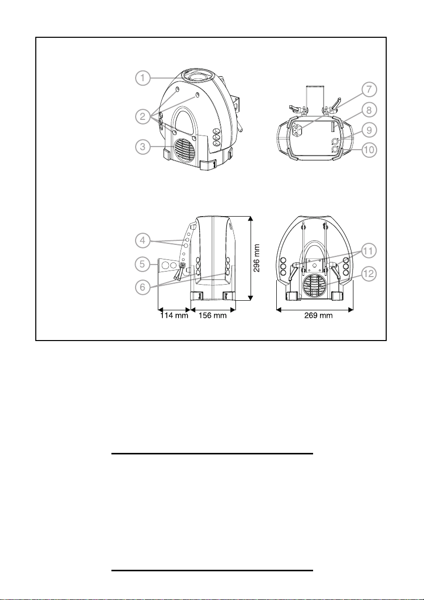
The CX-2 can be fastened directly to a suitable surface or to a rigging clamp by
means of its adjustable mounting bracket.
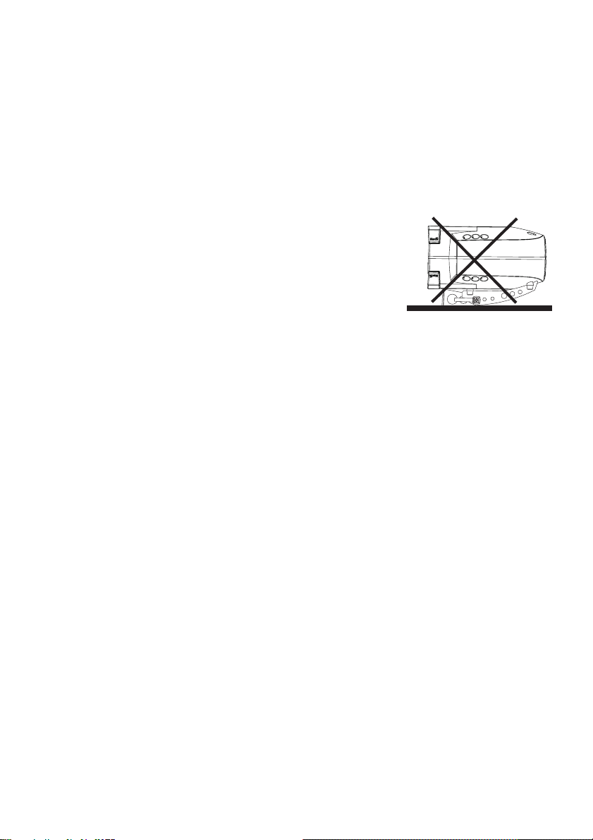
Do not lay the fixture flat on its mounting bracket
arms or position it so that there is less than 10 cm
(4 in.) clearance around the fan and air vents.
For maximum lamp life, do not place the fixture
directly on or beside a speaker cabinet or other
source of strong vibrations.
To rig the CX-2
Warning! Always use a secure means of secondary attachment. Block
access below the work area before proceeding.
1 Verify that the clamp (not included) is undamaged and can bear at least 10
times the fixture’s weight. Bolt the clamp securely to the bracket with a grade
8.8 (minimum) M12 bolt and lock nut, or as recommended by the clamp
manufacturer, through the 13 mm hole in the center of the mounting bracket.
2 If permanently installing the fixture, verify that the hardware (not included)
and mounting surface can bear at least 10 times the fixture’s weight. The four
6.2 mm holes and/or the 13 mm hole in the mounting bracket may be used.
3 Verify that the structure can support at least 10 times the weight of all
installed fixtures, clamps, cables, auxiliary equipment, etc.
4 Working from a stable platform, clamp or fasten the fixture to the structure.
5 Install a safety cable that can hold at least 10 times the weight of the fixture
through/over the support and through a hole in one of the aluminum arms.
6 Loosen the swivel locks and tilt the fixture to the desired angle. Turn the
swivel locks clockwise to tighten. If a swivel lock does not tighten fully, pull
the handle out, turn it counterclockwise, and retighten. Repeat as necessary.
7 Verify that the fixture is located at least 0.3 meters (12 in.) away from the
surface to be illuminated and at least 0.1 meters (4 in.) from any combustible
materials. Verify that the clearance around the fan and air vents is at least 0.1
meters (4 in.). Verify that there are no flammable materials nearby.

10 Data connection CX-2 user manual
D
ATA
CONNECTION
5
A reliable data connection begins with the right cable. For best results, use cable
specifically designed for RS-485 applications, available from your Martin dealer.
CONNECTIONS
The data sockets are wired with pin 1 to ground, pin 2 to signal - (cold), and pin 3
to signal + (hot) for compatibility with DMX devices. One or more adaptor cables
as shown below may be required for connnection to the controller or other lights.
To connect the data link
1 Connect a cable to the controller’s data output. If the output socket has a 5
pins, use a 5-pin male to 3-pin female adaptor. Lead the cable to the first
fixture and plug it into the data input.
2 Connect the output of the fixture closest to the controller to the input of the
next fixture. If connecting to a fixture with reversed-polarity (pin 3 cold),
insert a phase-reversing cable between the two fixtures. Continue connecting
fixtures output to input. Up to 32 devices may be connected on a serial link.
3 Terminate the link by inserting a male termination plug (P/N 91613017) into
the data output of the last fixture. A termination plug is simply an XLR
connector with a 120 ohm, 0.25 W resistor soldered across pins 2 and 3.
Phase-Reversing
Adaptor
Male Female
1
2
3
1
2
3
3-pin to 3-pin
P/N 11820006
Adaptor
Male Female
1
2
3
4
5
1
2
3
5-pin to 3-pin
P/N 11820005
Adaptor
Male Female
1
2
3
1
2
3
4
5
3-pin to 5-pin
P/N 11820004
Male XLR
1
2
3
Male
P/N 91613017
120
Termination Plug

CX-2 user manual Stand-alone operation 11
S
TAND
-
ALONE
OPERATION
6
The CX-2 may be operated without a controller in stand-alone mode. It may be
operated as a single unit or together with other CX-2s in “master/slave”
configuration.
Several options are available to modify stand-alone operation. These options are
selected using the DIP-switch as described below.
Important! The CX-2 transmits a signal when DIP-switch pins 2 and 10 are
set to ON. To avoid damage to the electronics, connect no
more than 1 transmitting device (master or controller) to the
data link.
SINGLE UNIT OPERATION
The fixture defaults to stand-alone mode with music trigger whenever power is
applied and there is no control signal. Options for trigger type, change speed, and
lamp intensity may be selected as described under “Stand-alone settings”.
MASTER / SLAVE OPERATION
Multiple CX-2s can be connected together, without a controller, for synchronized
“master/slave” operation in which the slaves mimic the behavior of the master,
which may be any one of the connected fixtures.
To connect units for master / slave operation
1 Connect the output of one CX-2 to the input of the next CX-2.
2 Connect additional CX-2s output to input. Up to 32 may be connected.
3 Terminate the link on both ends by inserting a
female
termination plug (P/N
91613018) into the data
input
of the first fixture and a
male
termination plug
into the data
output
of the last fixture. The female terminator may not be
required if the first fixture is the master.

12 Stand-alone operation CX-2 user manual
To set the master
Important! Set only 1 fixture as master (DIP-switch pin 2 and 10 ON).
1 Set DIP-switch pins 2 and 10 to ON.
2 Set DIP-switch pins 3, 5, 6, 7, 8, 9, and 11 to OFF.
3 Select options with DIP-switch pins 1, 4, and 12.
To set a slave
1 Set DIP-switch 10 to ON.
2 Set pins 1, 2, 3, 4, 5 and 11 to OFF.
3 Select options with DIP-switch pins 6, 7, 8, 9, and 12.
STAND-ALONE SETTINGS
DIP-switch pins 1-9 enable stand-alone options only when pin 10 is ON. When
pin 10 is off, the DIP-switch selects a DMX address. Pin 11 must be OFF for
stand-alone operation.
Pin 12 selects lamp power and works in all modes. Set it to ON for reduced lamp
voltage and longer lamp life; set it to OFF for full intensity.
The DIP-switch 10 setting takes effect only after the fixture has been turned off
and on.
Fixture Option Setting (0 = OFF, 1 = ON)
1234567891011
single or
master
auto trigger 0 1 0 0
10
music trigger 1 1 0 0
slow change 1 0 1 0
slave
random color 0 1
random gobo 0 1
inverted color 0 1
inverted gobo 0 1
102 3 4 51 86 7 9
ON
1211
102 3 4 51 86 7 9
ON
1211

CX-2 user manual MC-1 operation 13
MC-1
OPERATION
7
CX-2s with CPU firmware v 1.2 or higher are fully compatible with the Martin
MC-1 Controller. See the MC-1 user manual for additional information.
MC-1 SETTINGS
DIP-switch pin 10 must be set to OFF to enable MC-1 mode operation. Changes
to the setting take effect after the fixture has been turned off and on.
DIP-switch pins 6, 7, 8, and 9 select several control options that can be combined
to achieve powerful effects quickly and easily.
Pin 12 selects lamp power and works in all modes. Set it to ON for reduced lamp
voltage and longer lamp life; set it to OFF for full intensity.
Option Setting (0 = OFF, 1 = ON)
1234567891011
random color 1 0
random gobo 1 0
inverted color 1 0
inverted gobo 1 0

14 DMX operation CX-2 user manual
DMX
OPERATION
8
This section describes how to select the DMX operation mode and address using
the DIP-switch and briefly describes the programmable control options.
DMX MODES
The CX-2 has 2 DMX modes to choose from: a 1-channel mode that provides
control of the built-in stand-alone features, and a 4-channel mode that provides
full control of all effects.
To select DMX mode
1 Disconnect the fixture from power.
Set DIP-switch pin 10 to OFF.
2 To select 1-channel DMX mode, set DIP-switch pin 11 to ON.
3 To select 4-channel DMX mode, set DIP-switch pin 11 to OFF.
DMX ADDRESS
DIP-switch pins 1-9 are used to set the control address. The address, also known
as the start channel, is the first channel used to receive instructions from the
controller.
For independent control, each fixture must be assigned its own address and non-
overlapping control channels. Two CX-2s may share the same address only if they
are to respond identically: they will receive the same instructions and individual
control will not be possible.
To set the DMX address
1 Select an address for the fixture on your controller. Look up the DIP-switch
setting for the address in the table below.
2 Disconnect the fixture from power.
3 Set pins 1 through 9 to the ON (1) or OFF (0) position as listed in the table.

CX-2 user manual DMX operation 15
Find the address in the table. Read the settings for pins 1 - 5 to the left and read
the settings for pins 6 - 9 above the address. “0” means OFF and “1” means ON.
Pin 10 is always OFF for DMX operation.
',306ZLWFK#6HWWLQJ
3# #2))
4# #21
&<3333333344444444
&;3333444433334444
&:3344334433443344
&93434343434343434
&4 &5 &6 &7 &8
33333 6597<945;4934<55575895;;6536856;774977;7;3
43333 46698<:45<4944<655858:5;<6546866;874:77<7;4
34333 567 99 <; 463 495 4<7 559 58; 5<3 655 687 6;9 74; 783 7;5
44333 6689:<<4644964<855:58<5<46566886;:74<7847;6
33433 7699;4334654974<955;5935<56576896;;7537857;7
43433 86: 9< 434 466 498 4<: 55< 594 5<6 658 68: 6;< 754 786 7;8
34433 96;:34354674994<;5635955<765968;6<37557877;9
44433 :6<:443646849:4<<5645965<865:68<6<47567887;:
33343 ;73 :5 437 469 49; 533 565 597 5<9 65; 693 6<5 757 789 7;;
43343 <74:643846:49<5345665985<:65<6946<675878:7;<
34343 4375:743946;4:35355675995<;6636956<775978;7<3
44343 44 76 :8 43: 46< 4:4 536 568 59: 5<< 664 696 6<8 75: 78< 7<4
33443 4577:943;4734:553756959;6336656976<975;7937<5
43443 4678::43<4744:653856:59<6346666986<:75<7947<6
34443 47 79 :; 443 475 4:7 539 56; 5:3 635 667 699 6<; 763 795 7<7
44443 487::<4444764:853:56<5:463666869:6<<7647967<8
33334 497;;34454774:953;5735:563766969;7337657977<9
43334 4: 7< ;4 446 478 4:: 53< 574 5:6 638 66: 69< 734 766 798 7<:
34334 4;83;54474794:;5435755:763966;6:37357677997<;
44334 4<84;644847:4:<5445765:863:66<6:473676879:7<<
33434 53 85 ;7 449 47; 4;3 545 577 5:9 63; 673 6:5 737 769 79; 833
43434 5486;844:47<4;45465785::63<6746:673876:79<834
34434 5587;944;4834;55475795:;6436756:773976;7:3835
44434 56 88 ;: 44< 484 4;6 548 57: 5:< 644 676 6:8 73: 76< 7:4 836
33344 5789;;4534854;754957;5;36456776:973;7737:5837
43344 588:;<4544864;854:57<5;46466786::73<7747:6838
34344 59 8; <3 455 487 4;9 54; 583 5;5 647 679 6:; 743 775 7:7 839
44344 5:8<<44564884;:54<5845;664867:6:<7447767:883:
33444 5;93<54574894;;5535855;764967;6;37457777:983;
43444 5< 94 <6 458 48: 4;< 554 586 5;8 64: 67< 6;4 746 778 7:: 83<
34444 6395<745948;4<35555875;964;6836;57477797:;843
44444 6496<845:48<4<45565885;:64<6846;674877:7:<844

16 DMX operation CX-2 user manual
1-CHANNEL DMX OPERATION
The functions shown in the following table are available in 1-channel mode.
When a “stand-alone” function is selected, the fixture steps through a routine
using a built-in microphone to trigger the action to the beat of the music. Note that
multiple fixtures cannot be synchronized in this mode.
FULL DMX OPERATION
See also the DMX protocol on page 20.
Channel 1 controls the light intensity and the strobe rate. It also allows you to
execute a “stand-alone” program with random color and gobo change using
automatic or music trigger.
All effect wheels are reset to their home position when the fixture is powered up;
they can also be reset from the controller by sending a reset command on channel
1.
Channel 2 controls the position of the color wheel. When set to 100 percent, the
wheel moves to random positions using the trigger selected on channel 1.
Channel 3 controls the position of the gobo wheel. When set to 100 percent, the
wheel moves to random positions using the trigger selected on channel 1.
Channel 4 controls the speed of effect wheel rotation, allowing you to vary the
speed on controllers without cross-faders. If your controller has cross-faders, and
you use them, then set channel 4 to the “tracking” speed (0 percent).
DMX value Percent Function
0 - 10
11 - 20
21 - 80
81 - 115
116 - 140
141 - 175
176 - 210
211 - 255
0 - 4
5 - 7
8 - 31
32 - 45
46 - 55
56 - 68
69 - 82
83 - 100
Blackout (light off)
Open (light on)
Strobe
Stand-alone with slow music trigger
Stand-alone with medium music trigger
Stand-alone with fast music trigger
Stand-alone with random music trigger
Manual trigger area, crossover at 240 (94%)

CX-2 user manual Basic service 17
B
ASIC
SERVICE
9
The CX-2 requires simple routine maintenance. The maintenance schedule
depends heavily on the operating environment; please consult a Martin service
technician for recommendations.
Any service procedure not described here should be referred to a qualified
technician.
Important! Excessive dust, grease, and smoke fluid buildup degrades
performance and causes overheating and damage to the
fixture that is not covered by the warranty.
Warning! Disconnect the fixture from AC power before removing any
cover.
CLEANING
To clean optical components
Use care when cleaning optical components. The surface of the color filters is
fragile and small scratches may be visible.
1 Disconnect the fixture from AC power and allow the components to cool
completely.
2 Release the 4 cover locks by turning them a quarter-turn counterclockwise.
Lift the cover straight off.
3 Blow or vacuum away loose dust. Remove residues from lenses and filters
with a soft cloth or cotton swabs wetted with isopropyl alcohol. Regular
glass cleaner may also be used, but no residues may remain.
4 Rinse with distilled water. Mixing the water with a small amount of wetting
agent such as Kodak Photoflo will help prevent streaking and spotting.
5 Dry with a clean, soft and lint-free cloth or blow dry with compressed air.
6 Replace the top cover. To lock the 4 cover locks, turn them a quarter to a half
turn clockwise, until you feel them click.
Do not overtighten
.

18 Basic service CX-2 user manual
To clean the fan and air vents
To maintain adequate cooling, dust must be cleaned from the fan and air vents
periodically.
1 Remove the data and power cables and stand the fixture on end.
2 Remove dust and dirt from the fan blades and vent grills using a soft brush,
cotton swab, vacuum, or compressed air.
REPLACING FUSES
The CX-2 has 2 fuses. The main fuse holder is built in to the mains input socket.
The secondary fuse is located on the printed circuit board.
Warning! Never replace fuses with ones of a different rating!
To replace the main fuse
1 Unplug the mains cable from the input socket. Pry open the fuse holder and
remove the fuse.
2 Replace the fuse with one of the same type. The fuse rating is listed on serial
number label.
To replace the secondary fuse
1 Disconnect the fixture from AC power. Release the 4 cover locks by turning
them a quarter-turn counterclockwise. Lift the cover straight off.
2 The fuse is located right behind the data input connector. Pry out the
defective fuse and replace it with one of the same rating.
3 Replace the cover before applying power.

CX-2 user manual Troubleshooting 19
T
ROUBLESHOOTING
10
Problem Probable cause(s) Remedy
One or more of the fixtures is
completely dead. No power to fixture. Check that power is switched on
and cables are plugged in.
Primary fuse blown. Replace fuse.
Secondary fuse blown. Replace fuse.
Fixtures reset correctly but all
respond erratically or not at all
to the controller.
The controller is not connected. Connect controller.
XLR pin-out of the controller
does not match pin-out of the
first fixture on the link (i.e.
signal is reversed).
Install a phase-reversing cable
between the controller and the
first fixture on the link.
Fixtures reset correctly but some
respond erratically or not at all
to the controller.
Bad data link connection Inspect connections and cables.
Correct poor connections.
Repair or replace damaged
cables.
Data link not terminated with
120Ω termination plug. Insert termination plug in output
jack of the last fixture on the
link.
Incorrect addressing of the
fixtures. Check DIP-switch settings.
One of the fixtures is
transmitting as a master or is
defective.
Bypass one fixture at a time
until normal operation is
regained: unplug both
connectors and connect them
directly together. Have the
defective fixture serviced by a
qualified technician.
An effect fails to reset correctly. The effect requires mechanical
adjustment. Contact Martin technician for
service.
No light. Lamp missing or blown Disconnect fixture and replace
lamp.
Lamp cuts out intermittently or
burns out too quickly. Fixture is too hot. Allow fixture to cool.
The transformer setting does not
match local AC voltage. Check AC setting.

20 DMX protocol CX-2 user manual
DMX
PROTOCOL
A
Channel Value Percent Function
1
0 - 4
5 - 154
155 - 169
170 - 229
230 - 239
240 - 249
250 - 255
0 - 1
2 - 60
61 - 66
67 - 89
90 - 93
94 - 97
98 - 100
Dimmer, Strobe, Reset
Light off
Dimmer, closed to open
Dimmer full open
Strobe, fast to slow
Stand-alone, music trigger
Stand-alone, auto trigger
Reset
2
0 - 5
6 - 11
12 - 17
18 - 23
24 - 29
30 - 35
36 - 41
42 - 47
48 - 53
54 - 59
60 - 65
66 - 71
72 - 77
78 - 83
84 - 89
90 - 95
96 - 101
102 - 107
108 - 113
114 - 119
120 - 125
126 - 131
132 - 137
138 - 143
144 - 149
150 - 155
156 - 161
162 - 167
168 - 173
174 - 179
180 - 185
186 - 191
192 - 197
198 - 203
204 - 209
210 - 255
0 - 1
2 - 4
4 - 6
7 - 9
9 - 11
11 - 13
14 - 16
16 - 18
18 - 20
21 - 23
23 - 25
26 - 27
28 - 30
30 - 32
33 - 35
35 - 37
37 - 39
40 - 42
42 - 44
44 - 46
47 - 49
49 - 51
52 - 53
54 - 56
56 - 58
59 - 61
61 - 63
63 - 65
66 - 68
68 - 70
70 - 72
73 - 75
75 - 77
78 - 79
80 - 82
82 - 100
Color Wheel
Open
Open / Light blue 101
Light blue 101
Light blue 101/ Fern green 205
Fern green 205
Fern green 205 / Red 304
Red 304
Red 304 / Yellow 603
Yellow 603
Yellow 603 / Magenta 507
Magenta 507
Magenta 507 / Medium blue 108
Medium blue 108
Medium blue 108 / Deep orange 302
Deep orange 302
Deep orange 302 / Light green 204
Light green 204
Light green 204 / Cyan 104
Cyan 104
Cyan 104 / Pink 312
Pink 312
Pink 312 / Blue 111
Blue 111
Blue 111 / Amber 604
Amber 604
Amber 604 / Primary red 308
Primary red 308
Primary red 308 / Primary green 206
Primary green 206
Primary green 206 / Orange 306
Orange 306
Orange 306 / Split-color 1
Split-color 1
Split-color 1 / Split-color 2
Split-color 2
Random “stand-alone” position w/ music or auto trigger
Table of contents
Other Martin Professional Dj Equipment manuals