Marunaka V242L User manual

BRUSH CUTTER
DESBROZADORA
DEBROUSSAILLEUSE
ROÇADORAS
DECESPUGLIATORI
DRAAGBARE BOSMAAIER
TRAGBARE MOTORSENSE
MOTORLU TIRPAN
Model V242L
V242W
V262L
V262W
V282W
Modelo
Modèle
Modelo
Modèllo
Model
Model
Model
(ENGLISH) OPERATING MANUAL
(ESPAÑOL) MANUAL DE INSTRUCCIONES
(FRANÇAIS) MANUAL DE FONCTIONNEMENT
(PORTUGUÊS) MANUAL DE INSTRUÇÕES
(ITALIANO) MANUALE D’USO E MANUTENZIONE
(NEDERLANDS) HANDLEIDING
(DEUTSCH) BEDIENUNGSANLEITUNG
(TÜRKÇE) KULLANMA KILAVUZU
!!!!Make sure all operators study this Manual
carefully before using the brush cutter.
11MUKAIDANISHI-MACHI.KISSHOIN.MINAMI-KU.KYOTO,JAPAN.601-8307
info-e@marunaka-japan.co.jp
http://www.marunaka-japan.co.jp
CODE: 800204407
0802
1

Contents
ENGLISH
TECHNICAL DATA
SYMBOL MEANING
[1] GENERAL DESCRIPTION ......................................................
2
[2] SAFETY RULES .....................................................................
[3] SAFETY USAGE .....................................................................
[4] FUEL AND OIL.........................................................................
[5] SAFETY GUARD ASSEMBLY ................................................
[6] BLADE AND NYLON STRING HEAD ASSEMBLY .................
[7] ENGINE/ CLUTCH CASE ASSEMBLY ........................................
[8] HANDLE GRIP/HANDLE/THROTTLE WIRE ASSEMBLY ......
[9] STARTING AND STOPPING THE ENGINE ...........................
1
2
3
5
6
7
8
8
9
12
13
14
[10] HARNESS HANDLING METHOD ..........................................
[11] REGULAR MAINTENANCE ...................................................
[12] FAULT FINDING TABLE ........................................................

V282W
TJ027E GX25 TLE26 TJ027E GX25 TLE26 TJ035E TJ045E GX35 TLE33 TJ035E TJ045E GX35 TLE33 TJ045E
Unit without cutting attachment,
empty tank kg 5.4 5.9 5.6 6.1 6.6 6.3 6.5 7.3 7.2 6.9 7.5 8.4 8.4 7.9 8.6
Unit with specified cutting
attachment, empty tank kg 6.0 6.5 6.2 6.7 7.2 6.9 7.2 8.0 7.9 7.6 8.2 9.0 8.9 8.6 9.2
Unit with specified cutting
attachment, full tank kg 6.4 6.9 6.7 7.1 7.6 7.4 7.7 8.6 8.4 8.2 8.7 9.6 9.4 9.2 9.8
Volume Fuel tank l 0.5 0.58 0.6 0.5 0.58 0.6 0.7 0.9 0.63 0.8 0.7 0.9 0.63 0.8 0.9
Specified blade diameter mm
Specified blade thickness mm
Number of cutting teeth
Blade center hole diameter mm
Blade rotational speed at
maximum allowed engine speed rpm
Rotational direction of output shaft
Length mm 1835 1865 1845 1835 1865 1845 1850 1860 1875 1845 1850 1860 1875 1845 1860
Width mm 400 400 400 695 695 695 400 400 400 400 690 690 690 690 690
Height mm 295 310 300 480 480 480 325 335 340 330 525 525 525 525 525
Engine displacement cm326.3 25.0 25.6 26.3 25.0 25.6 34.4 45.4 35.8 32.6 34.4 45.4 35.8 32.6 45.4
kW 0.77 0.72 1.12 0.77 0.72 1.12 1.03 1.4 1.0 1.3 1.03 1.4 1.0 1.3 1.4
Engine speed at maximum power rpm 7500 7000 7500 7500 7000 7500 7000 7500 7000 7000 7000 7500 7000 7000 7500
Recommended maximum engine
speed rpm 8000 8000 8000 8000 8000 8000 8000 8000 8000 8000 8000 8000 8000 8000 8000
Output shaft speed rpm 5900 5900 5900 5900 5900 5900 5900 5900 5900 5900 5900 5900 5900 5900 5900
Recommended engine idling
speed rpm 2800 2800 2800 2800 2800 2800 2800 2800 2800 2800 2800 2800 2800 2800 2800
Engine speed at beginning of
clutch engagement rpm 3800 3800 3800 3800 3800 3800 3800 3800 3800 3800 3800 3800 3800 3800 3800
Fuel consumption gr/(kW h) 545/7500rpm 547/7000rpm 387/7500rpm 545/7500rpm 547/7000rpm 387/7500rpm 465/7000rpm 460/7500rpm 518/7000rpm 445/7000rpm 465/7000rpm 460/7500rpm 518/7000rpm 445/7000rpm 460/7500rpm
Idling (LPI)dB 75.9 72.6 76.7 75.9 72.6 76.7 77.2 74.0 72.5 75.2 77.2 74.0 72.5 75.2 74.0
Racing (LPR)dB 96.3 94.1 96.2 96.3 94.1 96.2 98.5 101.2 96.0 97.6 98.5 101.2 96.0 97.6 101.2
Idling (LWI)dB 87 83 88 87 83 88 87 84 86 87 87 84 86 87 84
Racing (LWR)dB 106 106 108 106 106 108 110 110 109 110 110 110 109 110 110
Guaranteed sound power level (LWA)dB 111
Idling (R L) m/s22.2 4.4 1.8 2.4 2.5 5.5 2.3 2.2 1.6 1.5 2.2 2.1 4.3 5.3 3.0 5.1 1.3 3.4 5.0 4.6 2.7 4.0 3.4 2.7 1.7 3.0 1.9 2.9 2.6 1.9
Racing (R L) m/s26.2 12.2 7.5 7.7 6.7 10.9 3.1 2.5 4.8 4.2 5.1 4.4 6.5 8.8 7.1 8.3 7.4 7.2 4.9 11.1 5.6 5.0 7.9 7.1 5.6 4.8 6.3 6.0 7.1 5.1
Equivalent vibration total values
(R L) m/s24.6 9.2 5.4 5.7 5.1 8.6 2.7 2.3 3.5 3.2 3.9 3.4 5.5 7.2 5.4 6.9 5.3 5.7 4.9 8.5 4.4 4.5 6.1 5.4 4.1 4.0 4.7 4.7 5.4 3.9
109 109 111 111
V262W
TECHNICAL DATA
Model
Engine
V242L V242W V262L
Masses
Cutting
attachment
255
1.4
3 , 4 or 8
25.4
8000
230
Gear ratio 1.36
Seen from above anticlockwis
External
dimensions
Vibration
levels
Maximum shaft brake power,measured in
accordance with ISO 8893
Rotational
speeds
Sound
pressure
levels
Sound
power
levels

SYMBOL MEANING
Warning-Caution
Do not use saw-blade
Minimum safety distance
Safety clothing:
1) Approved safety glasses of face shield
2) Approved safety helmet
3) Approved ear defender
4) Approved gloves
5) Approved safety footwear
Read operating manual carefully
Single handle should be locked in place marked !"#
Do not smoke while refuelling or while operating the machine
Beware of thrown objects
3

[1] GENERAL DESCRIPTION
- 1 -
1. Engine
2. Drive shaft housing
3. Trigger
4. STOP switch/throttle advance
5. Control handle
6. Blade
7. Harness
8. Spark plug
9. Air cleaner cover
10. Fuel tank cap
11. Muffler
12. Clutch case
13. Safety guard
14. Safety grip
15. Loop handle
1
6
5
3
2
9
8
7
411
10
14
13
12
1
6
5
3
2
9
8
411
10
14
1
11 8
14 9
4
10
15
13
12
6
512
2 3
13
V242L
V262L
V242W
V262W
V282W
V262
V282
V242

[2] SAFETY RULES
- 2 -
1. Make sure all operators study this manual carefully before
using the brush cutter. Do not allow children to use the
brush cutter.
2. When working with the brush cutter, wear suitable clothes.
a) Close fitting protective clothes (do not wear short
trousers or loose clothes)
b) Safety shoes (do not wear sandals and do not work
barefoot)
c) Heavy-duty gloves
d) Safety face shield or goggles
e) Ear protection
Make sure you know how to stop the engine and the blade
in an emergency (see section STARTING AND
STOPPING ENGINE). Never use the brush cutter when
tired, physically indisposed or under the effect of alcohol,
certain medicines or other drugs.
3. Be careful. Prolonged usage of this product may expose
the operator to vibration which can produce Whitefinger
disease (Raynand’s Phenomenon).
Always hold the brush cutter firmly with both hands.
When working, maintain a firm foothold. The brush cutter
must be used exclusively as recommended (see section
SAFETY USAGE).
Fig.2-1
Fig.2-4
4. Do not carry the brush cutter while the engine is running
even for short distances; switch off the engine put the
blade cover on the blade and carry the unit with the
cutting head behind you. When carrying the brush cutter
in a vehicle, secure it to prevent it from moving around.
Always empty the fuel tank before transporting the unit.
Start the brush cutter on a flat surface. When starting the
unit, ensure you have a firm footing. Make sure the blade
or the nylon string head does not touch the ground or any
obstacle.
Fig.2-2
Fig.2-5
5. Do not operate the brush cutter near fire or spilled petrol.
Do not run the engine in closed or poorly ventilated areas.
EXHAUST GASES ARE POISONOUS WHEN
INHALED. THEY CAN CAUSE SUFFOCATION AND
DEATH.
After refuelling, always wipe off any spilled fuel. Do not
smoke during this operation. Start the engine far away
from the refuelling area and from fuel containers
(minimum distance 3 meters). Do not refuel while the
engine is still running.
Fig.2-3

- 3 -
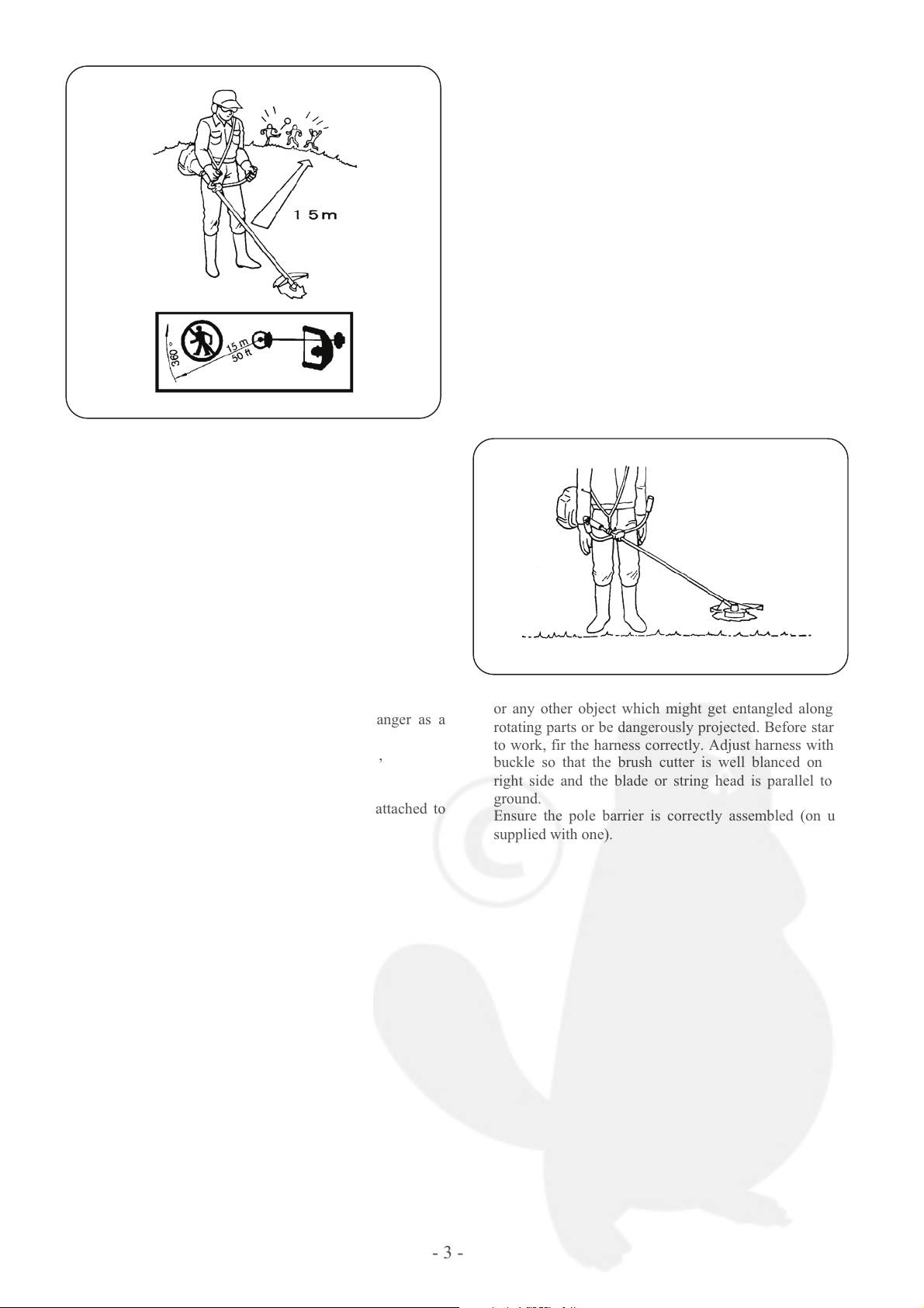
6. Keep people and animals away from working area
(minimum distance 15 meters).
If somebody should approach you, turn the engine off and
stop the blade (see section STARTING AND STOPPING
THE ENGINE), as during operation the blade or the nylon
string head might project grass, grit or other debris. The
blade is sharp. Be careful even if handling it when the
engine is off. Wear heavy-duty gloves. Turn the engine
off and wait for rotating parts to stop completely before
working on the machine or before touching the blade or
the string head.
DO NOT USE THE BRUSH CUTTER AT ALL, IF THE
SPECIFIED SAFETY GUARD IS NOT FIRMLY
ATTACHED (see sections SAFETY USAGE and
BLADES AND NYLON STRING HEAD ASSEMBLY).
Pay careful attention to any recommendations, as you
might put your life or somebody else’s in danger as a
result of:
a) possible contact with cutting or rotating parts,
b) possibility of projection of various objects
WARNING: Do not start engine if it is not attached to
the shaft, as the clutch might disintegrate.
[3] SAFETY USAGE
This product must be held to the right of the operator’s body.
This will exhaust fumes are directed away from the operator
and will not be obstructed by the operator’s clothing. If you
have not used a brush cutter before, spend some time in
becoming familiar with the controls and method of usage
before operation. Check the machine carefully before using
it. Make sure that there are no loosened screws, damaged
parts or fuel leakages. Replace damaged or excessively worn
accessories (blades, string heads, GUARDS).
Ensure all maintenance and repair work are carried out by an
authorized service center. Check the condition of the
antivibration components on a regular basis.
N.B. In order to maintain performance and safety, be sure to
use original spare parts and accessories. Avoid using the
brush cutter over excessively long periods of time.
Excessive amounts of vibration can be harmful.
Fig.2-6
Fig.3-1
1. Remove from the work area grit debris ropes, metal parts
or any other object which might get entangled along the
rotating parts or be dangerously projected. Before starting
to work, fir the harness correctly. Adjust harness with the
buckle so that the brush cutter is well blanced on your
right side and the blade or string head is parallel to the
ground.
Ensure the pole barrier is correctly assembled (on units
supplied with one).

- 4 -
2. The following accessories can be assembled to your brush
cutter. a) blade, b) nylon string head.
a)WHEN USING A BLADE, ENSURE THE CORRECT
GUARD IS FITTED.
b)WHEN USING A NYLON STRING HEAD,ENSURE
THE CORRECT GUARD IS FITTED.
When using the unit hold the front part of the machine
(blade or nylon string head) below your waist.
NYLON STRING HEAD:
Always make sure it has been correctly assembled (see
section ASSEMBLY and relevant chart).
The nylon string head is suitable to mow a lawn to trim grass
and weeds on edges or wherever there might be obstacles
like trees, fences or walls.
The nylon string head also reduces the likelihood of
damaging small plants and trees bark.
BLADE:
Always make sure it has been correctly assembled (see
section SAFETY and ASSEMBLY and relevant chart).
When fitting or changing a cutting device, ensure you follow
the instructions in the section “fitting a blade or nylon string
head” with extreme precision. Fit these cutting devices using
all and only the parts described, and in the correct order.
Fig.3-2
Fig.3-3
3.BLADES:
You can cut any type of grass, bushwood or shrub.
Operate the machine like a sickle always cutting at full
throttle.
N.B. This machine is designed so that the blade or nylon
string head is mounted for rotation in the anticlockwise
direction.
Fig.3-4
4. WARNING: Always use a well sharpened blade.
A blade with worn teeth besides providing poor
performance, might also generate a sudden thrust. This
can result in a violent sideways kick caused when the
blade touches against solid bodies. Such thrust might then
cause the operator to lose control of the machine itself. Do
not attempt to use a damaged blade but replace it with a
new one.
THRUST: Can occur when using any type of blade
within the risk area
; therefore it is advisable to cut
using the remaining area of the blade.

[4] FUEL AND OIL
- 5 -
1. 2-STROKE ENGINE
(KAWASAKI:TJ Series , MITSUBISHI:TLE Series)
This product is fitted with a 2-stroke engine and
therefore requires a 2-stroke fuel and oil mix. Use a high
quality 2-stroke engine oil using 2% (50:1) oil. In order to
obtain a good fuel mix, put the oil into the container
before the petrol.
Petrol
This engine can use leaded (4 star) or unleaded petrol with
a minimum octane rating of 90. When using unleaded
petrol mix it with 2% (50:1) of high quality synthetic oil
specifically made for 2-stroke engines.
IMPORTANT:Always shake this fuel mix vigorously
each time you use it.
Fuel mix properties deteriorate with time. We therefore,
recommend that you only make the quantity of fuel mix
you will need for each usage. Do no use fuel mix more
than a week old, as this could damage the engine.
WARNING: Do not smoke when re-fuelling.
Always open the fuel cap slowly.
Re-fuel in open spaces only, keeping away from naked
flames or sparks.
Always store fuel in an approved container.
Safety storage of fuel
Petrol is highly inflammable. Put out all cigarettes, pipes
and cigars before working with petrol. Avoid spilling
petrol. Store fuel in a cool well ventilated place, in an
approved container specifically designed for the purpose.
Never store engine with fuel in the tank in enclosed,
poorly ventilated areas, where fuel fumes may reach an
open flame, spark or pilot light such as in a furnace, water
heater, clothes dryer, etc. Petrol fumes can cause an
explosion or a fire. Do not store large amounts of fuel.
Fig.4-1
2. 4-STROKE ENGINE (HONDA: GX Series)
Petrol
This engine can use leaded (4 star) or unleaded petrol with
a minimum octane rating of 90.
CAUTION: Be sure to stop the engine before checking
the engine oil level. Do not restart the engine until you
have finished checking the oil.

[5] SAFETY GUARD ASSEMBLY
- 6 -
1. For safety reasons, it is imperative that the unit is used
with the correct guard when fitted with a grass cutting
blade. (Fig. 5-1)
Our standard tightening torque of bolt, screw and nut is as
follows:
Please be careful not to tighten them too tightly.
N.B. Bolt of grease-up port on gearcasing must be tightened
at 3.6 daN$m torque.
2. For a safety reasons, it is imperative that the unit is used
with the correct guard when fitted with a nylon head. (Fig.
5-2)
Use only manufacturer’s original blades.
Only use blades or nylon string heads clearly marked with
a maximum R.P.M. speed of at least 10,000 R.P.M.
Follow the fitting instructions carefully
Fig.5-1
Size
M4
M5
M6
M8
M10
Torque (daN$m)
1.6
3.1
5.1
12.2
24.5
Fig.5-2

[6] BLADE AND NYLON STRING HEAD
- 7 -
ASSEMBLY
Assemble the correct guard to suit the kind of blade or nylon
string head to be used (See section: SAFETY GUARD
ASSEMBLY).
1. Assemble the blade as illustrated.
a) Holder cutter (A) with blade (B) centering
b) Blade (B) with text and directional arrow facing
upwards
c) Cap cutter (C)
d) Stabilizer (D)
e) Blade locking nut (E) (Fig. 6-2)
2. Make sure that the blade core opening fits perfectly along
the centering collar on the holder cutter. Tighten
anticlockwise. While tightening, the blade assembly can
be held fast by inserting the wrench or the screwdriver
supplied into the holder cutter and gearcase holes. To do
this, rotate the cap until the two holes coincide.
A
3. Assemble nylon string head as illustrated.
Model: NV
a) Loosen the nylon string head NV, and leave Disc (B-1)
only.
b) Match the Disc with the center of the holder cutter
positionally.
c) Cap cutter
In the case of Model NV, the cap cutter (C) is a
dedicated part.
d) Blade locking nut (D) (Fig. 6-2)
e) Set the code cassette (B-2) on the Disc (B-1). For the
handling method, refer to the manual for the nylon
string head Model NV.
Model: Spool cutter
Mount the nylon string head after the cap cutter in
succession. (Fig. 6-4)
4. While tightening, the head assembly can be held fast by
inserting the wrench or the screwdriver supplied into the
holes as already shown for the blade assembly.
Fig.6-2 Fig.6-4
B-1
C
D
Fig.6-1
A
D
C
B
E
A
B
B-2
Fig.6-3

[7] ENGINE/ CLUTCH CASE ASSEMBLY
- 8 -
DENGER
Do not run the engine without clutch case
attached, as the clutch could fly off.
1. Assemble the engine onto the clutch case. Make sure the
shaft is fully and correctly up to the shank, then tighten
the four screws A. (Fig. 7-1)
[8] HANDLE GRIP/HANDLE/THROTTLE
WIRE ASSEMBLY
Mounting of handle grip
1. Double handle
Mount the control handle (A) on the handle (B) and the
grip (C) on the handle (D). Engage individual handles
with the grooves in the handle holder (F), hold them with
the handle holder (E), and fix them with bolts. Fix the
wire/cord Assy to the handle with a band (G). (Fig. 8-1)
2. Loop handle
The loop handle consists of the loop handle body (A), the
handle holder (B), setting bolts M5%30 (C) and nuts
M5 (D).
Set the loop handle body at the marked position on the
drive shaft housing, then attach and tighten the handle
holder (B) with the bolts (C) and nuts (D).
AFig.7-1
G
V262W
V282W
A
G
FC
B
D
E
A
V242W G
E
Fig.8-1
B
C
D
F
G
AC
Fig.8-2
B
Mark
D

Connection of throttle wire
- 9 -
Remove the air cleaner cover (A).
Attach the throttle wire (B). The normal play is 1 or 2 mm
when measured at the throttle wire end.
Attach the engine cord (C) to the engine (GX Series only).
Attach the cord from the control handle (D) to the engine
cord.
Install the air cleaner (A).
[9] STARTING AND STOPPING THE
ENGINE
MODEL: V242W V262W V282W
GX Series
C
BA
A
STARTING THE ENGINE
&ENGINE MODEL: GX Series , TLE Series
First, press the safety lever (C), and fully hold the lever
(B).Release your hand from the lever (B) in state with the
knob (A) pushed in the “'START” direction (Fig. 9-2).
Then,the throttle is fixed in the middle speed position to
facilitate easy start of the engine.
Start the engine in accordance with the engine operation
manual. After start of the engine hold the lever (B) again,
and leave your hand from it. Throttle advance is
cancelled,and the engine is put in the idling state. At that
time, the knob (A) moves to the position shown in Fig. 9-
3.
BFig.9-1
Fig.9-2
Fig.9-3
Fig.9-4
Fig.8-3
TJ Series
TLE Series
D
C
B
A
D
1(2 m
m

&ENGINE MODEL: TJ Series
- 10 -
Push knob (A) in the “'START” direction (Fig. 9-2).
Push the priming pump (D) several times (Fig. 9-5).
Move the choke lever (E) to the “START” position (Fig. 9-5).
Pull the recoil starter grip (F) firmly and rapidly until the
engine fires (Fig. 9-6).
NOTE: If you pull lever (B), the choke lever (E) will return
by itself.
NOTE: Please refer to the Engine Operation Manual.
STOPPING THE ENGINE
To stop the engine, push the knob (A) in the “'
STOP” direction (Fig. 9-4).
WARNING: When the engine is switched off, the rotating
part, blade or nylon string head, will keep on rotating for
afew seconds. Hold the machine until all parts come to a
standstill.
START
N.B. In an emergency the above mentioned delay in
stopping may be shortened by touching the blade parallel to
the grounds.
EF
G
D
Fig.9-7
Fig.9-5 The knob (G) on the control lever is a throttle positioner.(Fig.
9-7)
Turn the knob clockwise, and the engine rotational speed
changes toward the lower speed side when the lever (B) is
operated. The speed can be set to the higher side when the
knob is turned anticlockwise. Select the knob position in
conformance with the working condition.
N.B. If the knob is fastened excessively (clockwise), it
becomes impracticable to lock the knob (A) in the “'
START” position.
Fig.9-6

MODEL: V242L V262L
- 11 -
STARTING THE ENGINE
&ENGINE MODEL: GX Series , TLE Series
Press lever (J) and hold lever (I). Release levers (J) and (I)
while keeping knob (L) pressed. The throttle lever (I) is
now in its partial acceleration position, in order to let the
engine start more quickly and easily. Push knob (H) in the
“'START” direction (Fig. 9-9).
Start the engine according to its operation and
maintenance manual.
After starting the engine, pull throttle lever (I) once again
and release it right away in order to unlock it from the
partial acceleration position and to let the engine idle
when lever (I) is released.
&ENGINE MODEL: TJ Series
Push knob (H) in the “'START” direction (Fig. 9-9).
Push the priming pump (D:Fig. 9-5) several times.
Move the choke lever (E:Fig. 9-5) to the “START”
position.
Pull the recoil starter grip (F:Fig. 9-5) firmly and rapidly
until the engine fires (Fig. 9-6).
NOTE: If you pull lever (I), the choke lever (E:Fig. 9-5)
will return by itself.
J
HL
NOTE: Please refer to the Engine Operation Manual.
STOPPING THE ENGINE
In order to stop the engine, press button (H) into its“ STOP”
position (Fig. 9-10).
K
IFig.9-8 WARNING: When the engine is switched off, the rotating
part, blade or nylon string head, will keep on rotating for a
few seconds. Hold the machine until all parts come to a
standstill.
NOTE: In the event of an emergency, the time required for
the disc or the string cutter head to stop can be reduced by
resting the cutting tool level onto the ground. The ring nut
(K) located on the control handle is for adjusting the engine.
By turning ring nut (K) clockwise, the engine rpm is reduced
during the subsequent use of throttle lever (I).
Conversely, turning ring nut (K) counterclockwise raises the
engine rpm.
Therefore, adjust ring nut (K) according to the operating
conditions.
Fig.9-9
Fi
g
.9-10

[10] HARNESS HANDLING METHOD
- 12 -
In normal use of the reaper, set the harness side hook on the
hanger strap stem securely before starting the work. This
applies to both single and double harness. (Fig. 10-1)
For the harness fitting method, see Fig. 10-2.
Fi
g
.10-3
In the case of an emergency pull up the belt (red), and the
total machine can be separated from the harness. Be careful
not to operate the belt carelessly except for a case of
emergency. (Fig. 10-3)
Fi
g
.10-1
Fig.10-2

[11] REGULAR MAINTENANCE
From time to time make sure all brush cutter screws are
firmly secured. Replace damaged, worn, cracked or warped-
blades. Always make sure nylon string head and blade have
been assembled correctly (see section BLADE AND
NYLON STRING HEAD ASSEMBLY) and blade fastener
is tightened.
- 13 -
1. AIR FILTER
AIR FILTER CLEANING (at least every 25 working hours).
A dust clogged air filter may cause carburetor problems.
This may prevent the engine from reaching its maximum
r.p.m. and cause high fuel consumption and/or difficult
starting. Remove filter cover. Carefully clean the inside of
filter box. The filter can also be cleaned with compressed air.
2. GEARCASE
Every 50 working hours inject the gearcase with gear grease
under high pressure through hole A.
3. SPARK PLUG
electrode ca
p
Fi
g
.11-3
From time to time (at least every 50 hours) remove and
clean the spark plug and check the electrode cap. Replace
spark plug about every 100 working hours or whenever it is
extremely encrusted.
Heavily encrusted electrodes can result from an incorrect
carburetor setting or from wrong fuel mixture (too much oil
in the petrol) or a poor quality oil in the fuel mix. Check and
correct.
Please refer to the Engine Operation Manual for information
about changing the spark plug and the electrode cap.
Fi
g
.11-1
A
Fi
g
.11-2

- 14 -
[12] FAULT FINDING TABLE
Engine will
not start.
Engine will not
Start of run
badly.
The brush
cutter does
not cut well.
Engine runs fast
but loses power
when cutting.
Check STOP switch is in
the position I. ))
Control fuel level min.
25% tank capacity. ))
Check air filter is clean. )
Remove spark plug, dry it,
clean it and adjust it, and
replace it, if necessary.
))
Control and adjust the
carburetor screws if
necessary.
)))
Change fuel filter.
Contact your dealer. )
Carefully follow the blade
assembly instructions.
)
Check blade is sharp.
Otherwise, contact you
dealer.
)
This manual suits for next models
4
Table of contents
Other Marunaka Brush Cutter manuals
Popular Brush Cutter manuals by other brands

EMAK
EMAK Efco DS 2000 Operators instruction book

Husqvarna
Husqvarna 125C Workshop manual

Brush Wolf
Brush Wolf Closed Front Series Operator's manual

Husqvarna
Husqvarna 555FX Operator's manual

McCulloch
McCulloch Cabrio 246/25 cc instruction manual

Grizzly
Grizzly MTS 30 AC Translation of the original instructions for use